Loading ...
Loading ...
Loading ...
Description
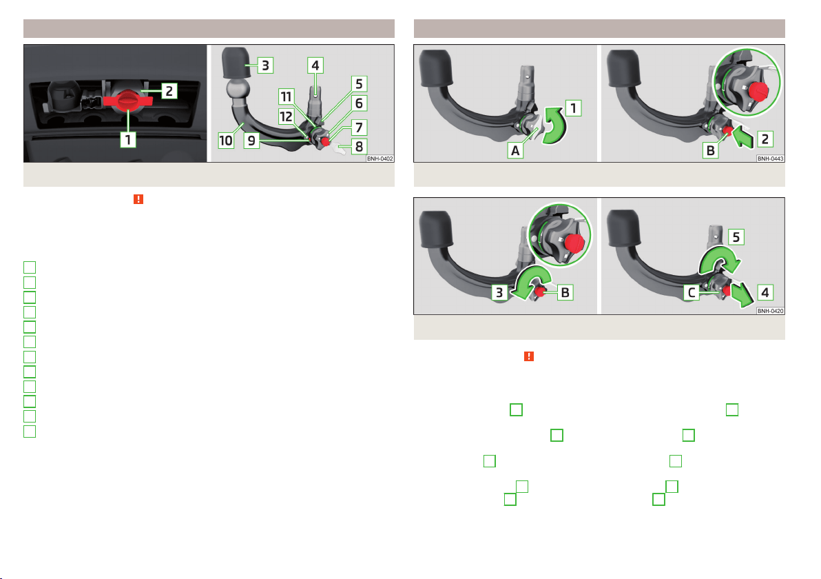
Fig. 217 Carrier for the towing device / tow bar
Read and observe on page 183 first.
The ball rod is detachable and is located in the stowage compartment for the
spare / emergency wheel.
Support for the towing device and tow bar » Fig. 217
Cap
Mounting recess
Protective cap
Locking ball
Centering
Hand wheel
Key
Lock cap
Red marking on the hand wheel
Tow bar
Green marking on the hand wheel
White marking on tow bar
1
2
3
4
5
6
7
8
9
10
11
12
Adjusting the ready position
Fig. 218 Remove cap from the lock / insert key into the lock
Fig. 219
Setting the ready position
Read and observe on page 183 first.
The tow bar can only be fitted if it is in the ready position.
›
Grip the tow bar below the protective cap.
›
Remove the cover
A
from the lock in the direction of the arrow
1
» Fig. 218.
›
Insert the key into the lock
B
in the direction of arrow
2
, so that the arrow
on the key symbol shows.
›
Turn the key
B
to the stop in the direction of arrow
3
, so that the arrow on
the key symbol shows » Fig. 219.
›
Pull the hand wheel
C
in the direction of the arrow
4
and turn in the direc-
tion of the arrow
5
to the stop. The hand wheel
C
remains locked in this
position.
184
Driving
Loading ...
Loading ...
Loading ...