Loading ...
Loading ...
Loading ...
SDS6000L User Manual
2 3 8 i n t . s i g l e n t . c o m
Configuration
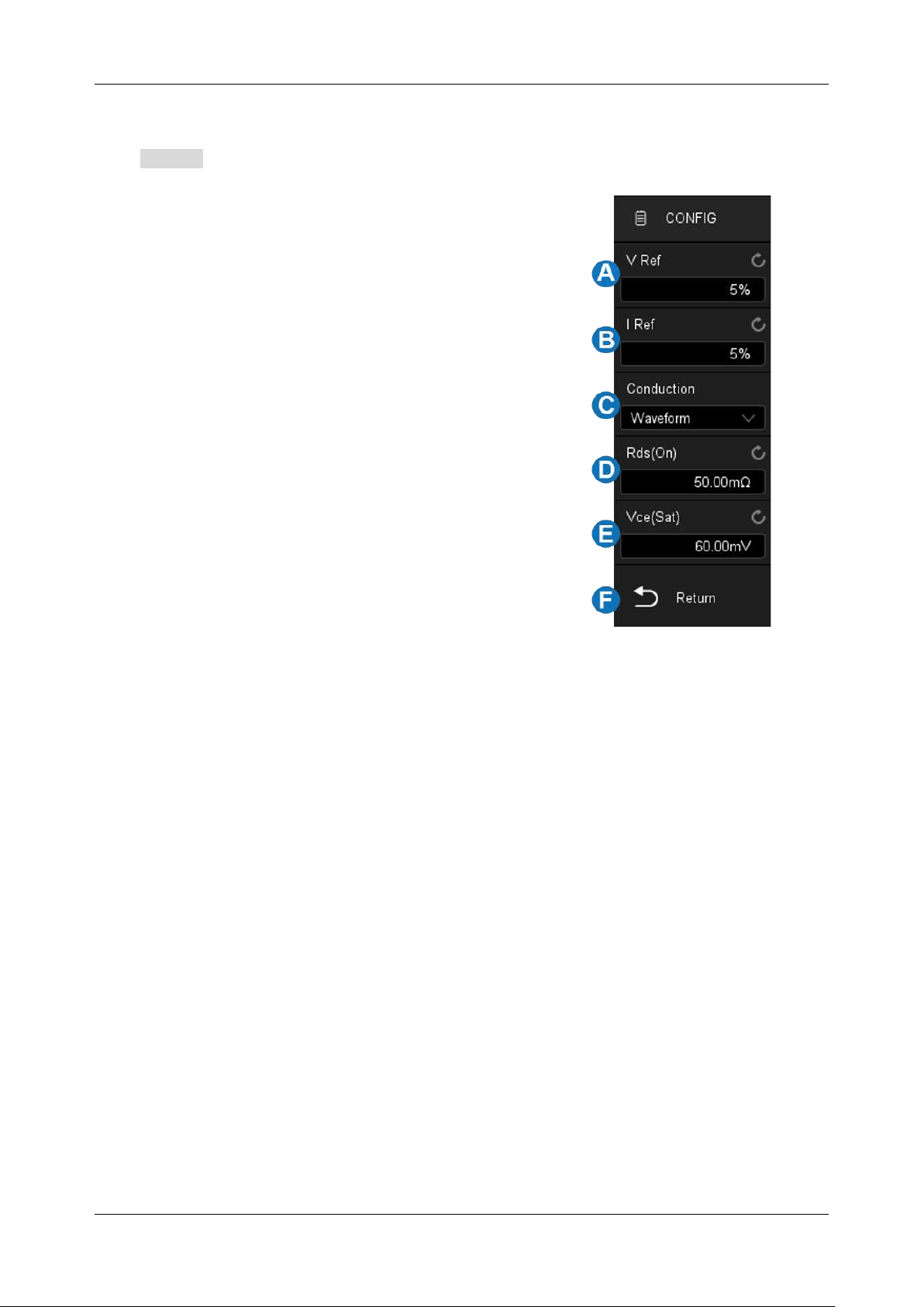
Click Config to recall the configuration dialog box:
A. Set the voltage reference, i.e. the switch level at the
edge of the input switch. This value is a percentage of
the maximum switching voltage. Adjusting the value
to ignore background noise. This value is used to
determine the threshold hysteresis of the switch edge
B. Set the current reference, i.e. the switch level at the
beginning of the input switch edge. This value is the
percentage of the maximum switching current. This
value can be adjusted to ignore background noise or
invalid offset that is difficult to eliminate in the current
probe. This value is used to determine the threshold
hysteresis of the switch edge
C. Set the conduction type (Waveform, Rds(on) or
Vce(sat))
D. Set Rds(on) resistance
E. Set Vce voltage
F. Return to the previous menu
Conduction Type
Waveform
-- The power waveform uses the original data, and the calculation formula is P = V * I, E =
P * T.
Rds (on)
-- In the on area (where the voltage level is lower than the voltage reference (adjustable)),
the power calculation formula is P = I
2
* Rds (on). In the off area (where the current level is lower than
the current reference (adjustable)), the power calculation formula is P = 0 watt.
Vce (sat)
-- In the on area (where the voltage level is lower than the voltage reference (adjustable)),
the power calculation formula is P = Vce (sat) * I. In the off area (where the current level is lower than
the current reference (adjustable)), the power calculation formula is P = 0 watt.
Loading ...
Loading ...
Loading ...