Loading ...
Loading ...
Loading ...
SDS6000L User Manual
int. s i g l e n t . c o m 1 2 5
14.3 SPI Trigger and Serial Decode
This section covers triggering and decoding SPI signals. Please read the following for more details:
"SPI Signal Settings", "SPI Trigger" and "SPI Serial Decode".
14.3.1 SPI Signal Settings
Connect the CLK, MOSI, MISO, and CS signals to the oscilloscope and set the mapping relation
between channels and signals. Then set the threshold level of each signal. The process of specifying
the source and threshold is similar to "I2C Signal Settings".
CLK
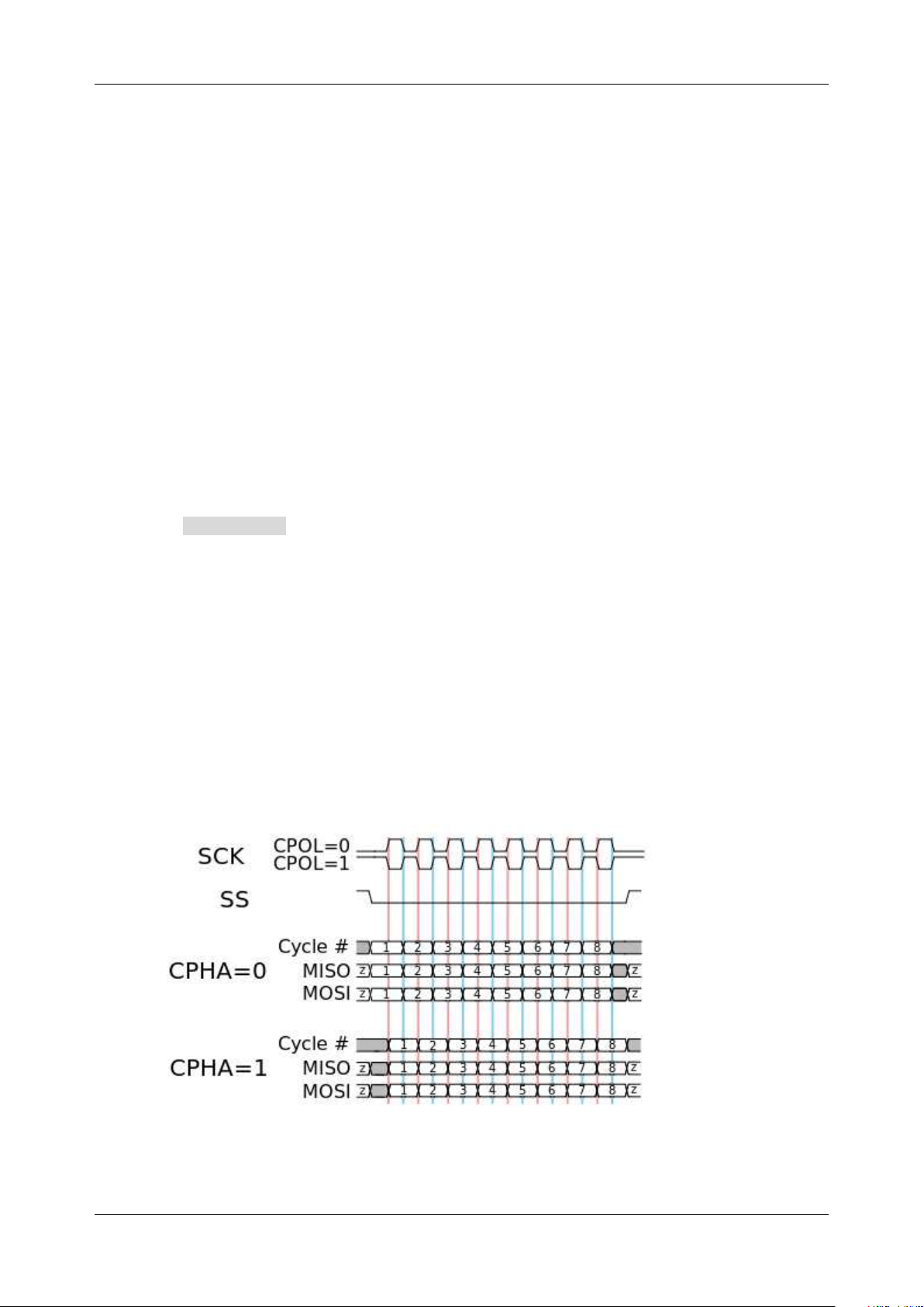
In addition to specifying the source and the threshold level, for the CLK signal, it is also necessary to
specify the Edge Select .
Rising–Data latched on the rising edge of the clock.
Falling–Data latched on the falling edge of the clock.
The user can select the edge according to the actual phase relationship between the clock and the
data of the SPI bus. Referring to the following figure, when the falling edge of the clock is aligned with
the data, the rising edge is selected to latch the data. When the rising edge of the clock is aligned with
the data, the falling edge is selected to latch the data.
Loading ...
Loading ...
Loading ...