Loading ...
Loading ...
Loading ...
SDS6000L User Manual
1 2 6 i n t . s i g l e n t . c o m
CS
The CS signal should be set to correct CS Type , including CS, ~CS, and Clock Timeout.
CS – Active high. The CS signal needs a complete rising edge in the screen to be regarded as
active.
~CS – Active low. The ~CS signal needs a complete falling edge in the screen to be regarded as
active.
Clock Timeout – It is not necessary to specify the source and the threshold level for the CS signal.
The only parameter for the CS signal is the timeout Limit, which is the minimum time that the clock
signal must be held idle before the oscilloscope acquires valid data. This setting is suitable for the
case where the CS signal is not connected, or the number of oscilloscope channels is insufficient
(such as two-channel oscilloscopes).
The method of copying settings is the same as I2C signal settings. See "I2C Signal Settings" for details.
Example:
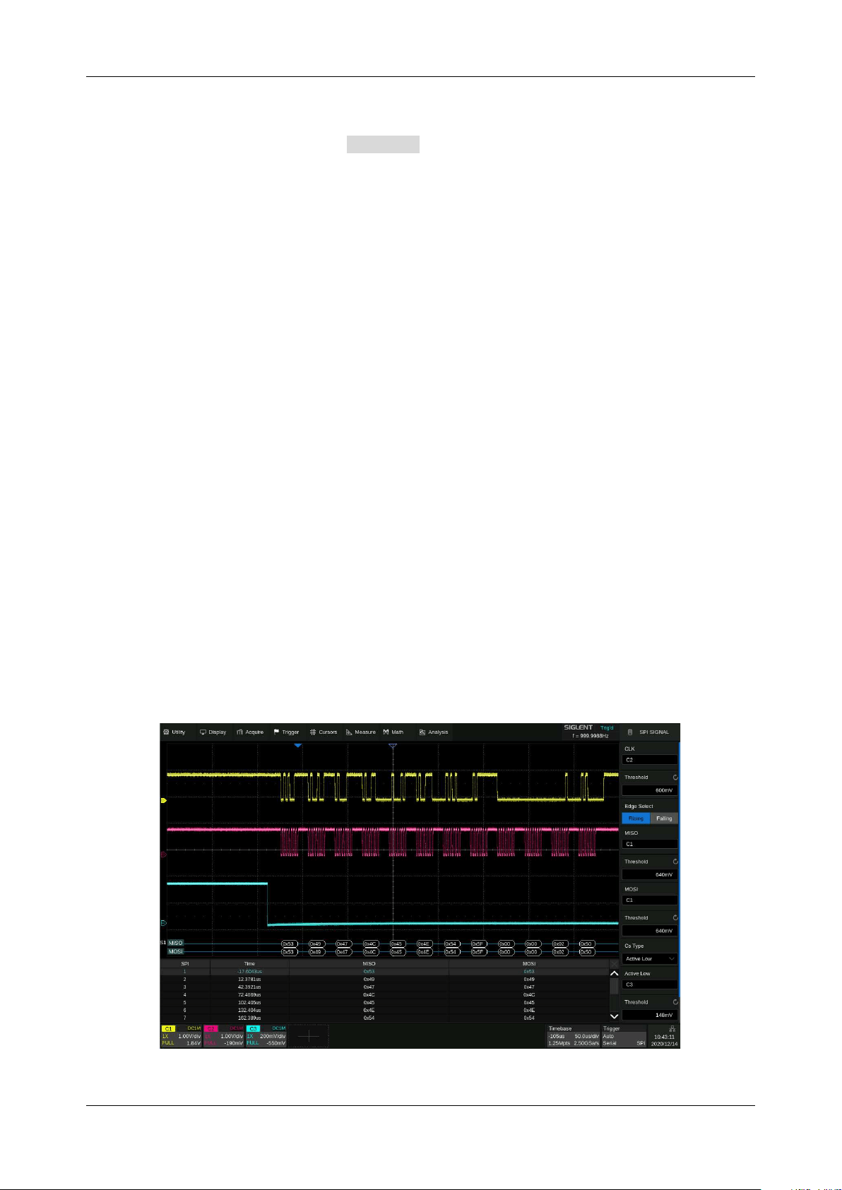
Connect the data, CLK, and ~CS signals of an SPI bus respectively to C1, C2, and C3. Data width =
8-bit, Bit order = MSB, CS polarity = active low, and 12 data bytes are transmitted in one frame.
In the SPI trigger signal menu, set the source and threshold of CLK, MISO, and CS signals, then copy
the trigger settings to decoding. Adjust the timebase, so that there is a falling edge on the CS signal
shown on the screen:
Loading ...
Loading ...
Loading ...