
Loading ...
Loading ...
Loading ...
I/O
Applications
199
6
Force Output: Click to test signal to the selected device.
Signal Type: Select a signal type: N/O (Normal Open), N/O Toggle, N/O Pulse, N/C (Normal
Closed), N/C Toggle, and N/C Pulse. For Toggle output type, the output continues to be triggered
until a new input trigger ends the output. For Pulse output type, the output is triggered for the
amount of time you specify in Sec field.
Keep Last Toggle Status: See Keeping Last Toggle Status later in this chapter.
Note: PTZ camera and I/O devices cannot be assigned to the same port at the same time.
6.1.3 Latch Trigger
Instead of constant output alarm in N/O and N/C during the input trigger, the Latch Trigger option
provides a momentary output trigger.
Setting up Latch Trigger
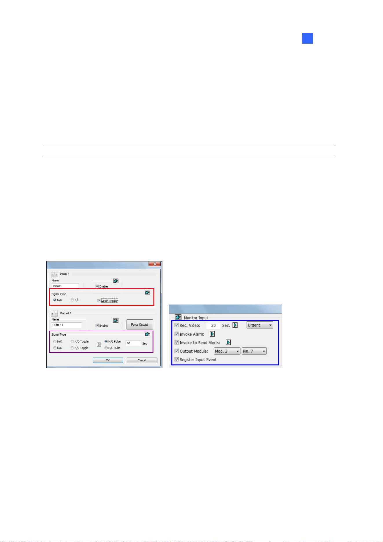
In the I/O Device dialog box (Figure 6-1), select Latch Trigger.
I/O Device Setup I/O Application Setting
Figure 6-5
Application Example
In the above scenario, Input 4 is set to N/O and Latch Trigger. When Input 4 is triggered:
The camera starts recording for 30 seconds using the frame rate settings for Urgent Event and
stops itself when the next input triggers (see the Rec Video option in the blue box).
Computer Alarm sounds once (see the Invoke Alarm option).
The output (Module 3, Pin 7) is triggered simultaneously based on the Latch Trigger mode (see
the illustrations below).
Loading ...
Loading ...
Loading ...