
© 2022 GeoVision, Inc. All rights reserved.
Under the copyright laws, this manual may not be copied, in whole or in part,
without the written consent of GeoVision.
Every effort has been made to ensure that the information in this manual is
accurate. GeoVision, Inc. makes no expressed or implied warranty of any kind
and assumes no responsibility for errors or omissions. No liability is assumed
for incidental or consequential damages arising from the use of the information
or products contained herein. Features and specifications are subject to
change without notice.
GeoVision, Inc.
9F, No. 246, Sec. 1, Neihu Rd.,
Neihu District, Taipei, Taiwan
Tel: +886-2-8797-8377
Fax: +886-2-8797-8335
http://www.geovision.com.tw
Trademarks used in this manual: GeoVision, the GeoVision logo and GV
series products are trademarks of GeoVision, Inc. Windows is the registered
trademark of Microsoft Corporation.
March 2022
Scan the following QR codes for product warranty and technical support
policy:
[Warranty] [Technical Support Policy]

i
GV-VMS Trial Version
GV-VMS is a comprehensive video management system that records up to 64 channels of
GeoVision and/or third-party IP devices. GeoVision offers a 60-day trial period that allows you to
connect to 16 channels of third-party IP devices without license. A “Trial Version” watermark will
appear on the live view and recorded files for the 16 channels of third-party IP devices.
Note:
1. If you insert a dongle for third-party IP devices, the dongle license will override the trial version
and the 16 trial channels will no longer be supported.
2. You cannot remotely access the trial channels using remote applications such as GV-Control
Center, etc.
Once the trial period expires, you will need to purchase dongles to connect to third-party IP devices.
See Dongle in Chapter 1 for details.
Login Credential Limitation
Special characters ‘@’ and ‘:’ are not supported to be used as the login username and/or password of
GV-VMS.

ii
GPU Decoding
GPU (Graphics Processing Unit) decoding can lower the CPU loading and increase the total frame
rate supported by a GV-VMS. GPU decoding can be performed by an onboard GPU, external GPU,
or both, under the following specifications.
Onboard GPU: GPU decoding is only supported when using the following Intel CPU:
For H.264 Video Compression
2
nd
~ 8
th
Generation Intel Core i3 / i5 / i7 Desktop Processors
9
th
~ 11
th
Generation Intel Core i3 / i5 / i7 / i9 Desktop Processors
For H.265 Video Compression
6
th
~ 8
th
Generation Intel Core i3 / i5 / i7 Desktop Processors
9
th
~ 11
th
Generation Intel Core i3 / i5 / i7 / i9 Desktop Processors
External GPU: GPU decoding is only supported when using NVIDIA graphics cards with compute
capability 3.0 or above and memory 2 GB or above. To look up the compute capability of the NVIDIA
graphics cards, refer to: https://developer.nvidia.com/cuda-gpus
.
Note:
1. One external NVIDIA graphics card can be supported by GV-VMS17.1 or later to perform GPU
decoding at free of charge.
2. NVIDIA GeForce GTX 1060 is not supported.

iii
Onboard GPU + external GPU: To have both the onboard and external GPU to perform GPU
decoding, the GPUs must follow their respective specifications listed above.
Note:
3. If you have both onboard external GPU installed, the onboard GPU must be connected to a
monitor for H.264 / H.265 GPU decoding.
4. CUDA compute capability 5.0 or higher is required to ensure optimal performance. For more
information, see Total frame rate and number of channels supported
Software Specifications
GPU decoding is only supported under the following operating system, resolution, and codec.
2nd Gen
3rd ~ 4th Gen
6th Gen
7th Gen
8th ~ 11th Gen
OS
64-Bit
Windows 7 / 8 / 8.1 / 10 / Server 2008
R2 / Server 2012 R2 / Server 2016 /
Server 2019
Windows 10
Server 2016 /
Server 2019
Windows 10 / 11
Server 2016 /
Server 2019
Resolution
1 MP /
2 MP
1 MP / 2 MP / 3 MP / 4 MP / 5 MP / 8 MP / 12 MP
Codec
H.264
H.264 / H.265
Note: Make sure your PC meets the system requirements before installing or upgrading to Windows
11. See Microsoft’s website for details.
Multi-Channel Playback
Multi-channel playback in ViewLog has been enhanced to improve the smoothness of the video by
producing higher frame rate. However, playing back multiple channels at high resolution can increase
the CPU loading especially if GV-VMS is processing other tasks simultaneously. As a result of the
high CPU loading, dropped frames may sometimes occur in recorded video when playing back
multiple megapixel channels. To avoid the problem, it is recommended to play back megapixel
video in single view.
GDPR Practice
For details on how GeoVision Inc. is committed to helping users become GDPR (General Data
Protection Regulation) compliant, visit the GDPR Consent Request.
iv
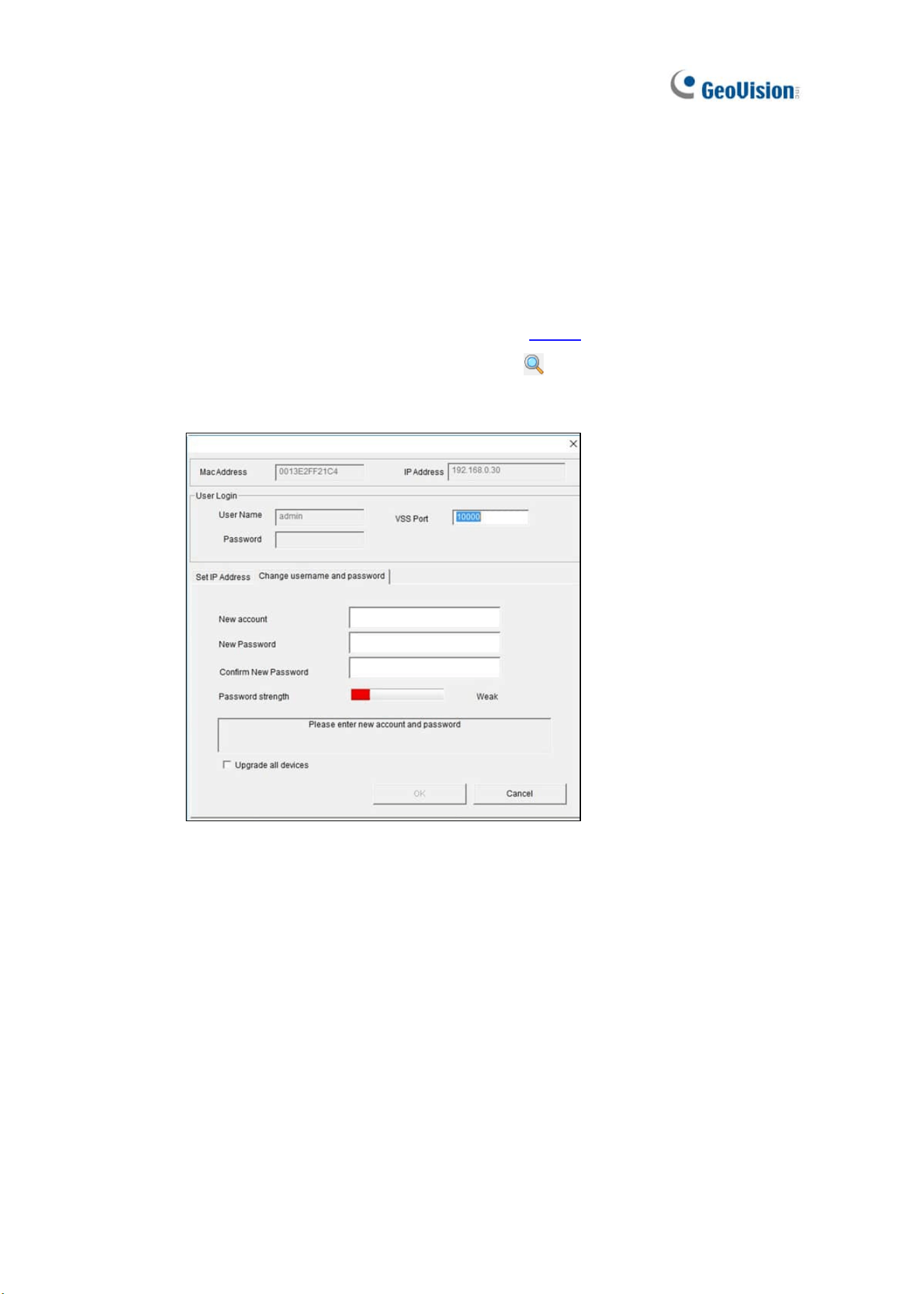
Creating Camera’s Login Credentials
In order to connect to GV-VMS, after purchasing a new GV-IP camera or factory resetting your GV-IP
camera, you need to set up a login username and password for that camera.
1. Download and install GV-IP Device Utility from our website
.
2. On the GV-IP Device Utility window, click Search
to search for your camera.
3. Double-click your camera in the GV-IP Device Utility list. This dialog box appears.
4. Click the Change Username and Password tab to type a new username and password.
5. Optionally click Upgrade all devices to use the same username and password on all
other devices.

v
Contents
GV-VMS Trial Version…………………….…….…......................……i
Login Password Limitation…………….…….…......................……i
GPU Decoding….…………………..............................……………….ii
Multi-Channel Playback…………………………………………..……..iii
GPDR Practice…………………….................……………….…………iii
Creating Camera’s Login Credentials.…………..……………….. iii
1
Configuring Main System ............................. 3
1.1 Installing GV-VMS .................................................................................................. 3
1.1.1 License .................................................................................................3
1.1.2 Minimum System Requirements .......................................................... 4
1.1.3 Options .................................................................................................5
1.1.4 Minimum Network Requirements .........................................................6
1.1.5 Installing GV-VMS................................................................................. 7
1.2 Getting Started .......................................................................................................8
1.2.1 Main Screen .......................................................................................... 9
1.2.2 Adding Cameras .................................................................................10
1.2.3 Accessing Live View ...........................................................................11
1.2.4 Enabling Recording............................................................................. 11
1.2.5 Playing Back Video ............................................................................. 12
1.3 Recording Settings.............................................................................................. 13
1.3.1 Setting up Global Recording Settings for All Cameras ......................14
1.3.2 Setting up Recording Settings for Individual Cameras ......................17

vi
1.3.3 Setting up the Video Storage Location............................................... 19
1.3.4 Setting up Motion Detection ............................................................... 20
1.4 Live View and Layouts ........................................................................................ 23
1.4.1 Utilizing Live View Functions..............................................................23
1.4.2 Arranging Live View Layouts..............................................................25
1.4.3 Setting up Zoom Window ................................................................... 26
1.4.4 Setting up Scan Window .................................................................... 27
1.4.5 Setting up Popup Window..................................................................29
1.4.6 Setting up Focus View........................................................................ 29
1.4.7 Automatic Switch among Different Live View Layouts.......................30
1.5 Starting Monitoring.............................................................................................. 31
1.6 System Configuration .........................................................................................32
1.6.1 Configuring General Settings ............................................................. 32
1.6.2 Customizing Startup Settings ............................................................. 34
1.6.3 Customizing Display Position and Panel Resolution .........................35
1.6.4 Setting up E-mail Notifications............................................................ 36
1.6.5 System Idle Protection ....................................................................... 38
1.6.6 Configuring Fast Key Lock .................................................................39
1.7 Account and Password....................................................................................... 39
1.7.1 Creating an Account........................................................................... 39
1.7.2 Configuring Account Settings.............................................................40
1.7.3 Changing or Retrieving Password at Login........................................42
1.7.4 Preventing Unauthorized System Termination................................... 42
1.7.5 Setting up a Startup Auto Login User................................................. 43
1.7.6 Setting up Limits on Playback Time ...................................................43
1.8 Schedule............................................................................................................... 44
1.8.1 Creating a Schedule with Setup Wizard............................................. 45
1.8.2 Creating a Schedule Manually ...........................................................47
1.8.3 Exporting and Importing Schedule Settings ....................................... 48
1.9 System Log .......................................................................................................... 48
1.9.1 Setting up System Log .......................................................................48
1.9.2 Viewing System Log...........................................................................50
1.10 Other Functions ................................................................................................. 52
1.10.1 Popping up Live View.......................................................................52
1.10.2 Adjusting to Daylight Saving Time ...................................................53
1.10.3 Setting up Network Failure Detection...............................................54
1.11 PTZ Camera ........................................................................................................ 55
1.11.1 Accessing PTZ Control Panel and Auto Functions .......................... 56

vii
1.11.2 Setting up Idle Protection and Advanced Functions ........................ 58
1.12 QView.................................................................................................................. 59
1.13 Storyline .............................................................................................................60
1.13.1 Creating a Storyline in Live View .....................................................60
1.13.2 Creating a Storyline in Video Playback ............................................ 61
1.13.3 Creating a Storyline in QView .......................................................... 61
1.13.4 Accessing the Storyline .................................................................... 62
1.14 GV-VR360 Dewarped View ................................................................................ 62
2
IP Camera Setup .................................65
2.1 Adding IP Cameras.............................................................................................. 65
2.1.1 Adding Cameras Manually .................................................................66
2.1.2 Scanning Camera............................................................................... 68
2.1.3 Mapping GV-IP Cameras Using GV-IP Device Utility ........................68
2.1.4 Adding Cameras of Mobile Devices using GV-Live Streaming.......... 69
2.2 Configuring Individual IP Cameras.................................................................... 69
2.2.1 Configuring Video Setting................................................................... 70
2.2.2 Configuring Audio Setting................................................................... 72
2.2.3 Configuring General Setting............................................................... 73
2.3 Connection through RTSP, ONVIF & PSIA ........................................................ 74
2.4 On Demand Display............................................................................................. 77
3
Video Analysis ....................................81
3.1 Object Counting and Intrusion Alarm................................................................ 81
3.1.1 Objecting Counting............................................................................. 81
3.1.2 Intrusion Alarm ...................................................................................84
3.2 Object Index .........................................................................................................87
3.2.1 Setting up Object Index ...................................................................... 87
3.2.2 Viewing Object Index.......................................................................... 89
3.2.3 Searching Object Index ......................................................................90
3.3 Automatic Video Snapshots ............................................................................... 91
3.3.1 Setting up Video Snapshots ............................................................... 91

viii
3.3.2 Searching Video Snapshots ............................................................... 92
3.4 Face Detection ..................................................................................................... 93
3.4.1 Setting up Face Detection ..................................................................93
3.4.2 Searching Face Detection Snapshots................................................ 94
3.5 Face Count ........................................................................................................... 95
3.5.1 Installing the Camera ......................................................................... 95
3.5.2 Setting up Face Count........................................................................96
3.6 Face Recognition................................................................................................. 99
3.6.1 Enrolling Face Data............................................................................ 99
3.6.2 Defining Access Schedule................................................................ 101
3.6.3 Configuring Face Setting..................................................................102
3.6.4 Recording Recognition Events ......................................................... 102
3.6.5 Tracking Recognized Faces............................................................. 104
3.6.6 Configuring Recognition Alerts and Recognition Database ............. 108
3.6.7 Tracking Recognized Faces............................................................. 109
3.7 Privacy Mask Protection ................................................................................... 112
3.7.1 Setting up a Privacy Mask................................................................ 112
3.7.2 Granting Access Privileges to Recoverable Areas ..........................113
3.8 Panorama View .................................................................................................. 114
3.8.1 The Main Window............................................................................. 114
3.8.2 Stitching a Panorama View with Overlapping Areas........................ 115
3.8.3 Easy Mode with No Overlapping Areas ........................................... 117
3.8.4 Accessing a Panorama View ........................................................... 119
3.9 Video Defogging ................................................................................................ 120
3.10 Video Stabilization ...........................................................................................121
3.11 Wide Angle Lens Dewarping........................................................................... 122
3.12 Crowd Detection .............................................................................................. 124
3.13 Advanced Scene Change Detection .............................................................. 126
3.14 Advanced Unattended Object Detection ....................................................... 128
3.15 Advanced Missing Object Detection ............................................................. 131
3.16 Text Overlay ..................................................................................................... 133
3.17 Fisheye View ....................................................................................................134
3.17.1 Setting up Fisheye View.................................................................135
3.17.2 Setting up a Third-Party Fisheye Camera...................................... 137
3.17.3 Object Tracking ..............................................................................139
3.18 Video Analysis by Camera .............................................................................. 143
3.19 Heat Map........................................................................................................... 146
3.19.1 Enabling Heat Map.........................................................................146
ix
3.19.2 Accessing the Heat Map in Recordings ......................................... 148
3.20 Event Alert through E-mail Notifications.......................................................149
3.21 PTZ Object Tracking........................................................................................150
3.21.1 Dual-Camera Tracking ................................................................... 150
3.21.2 Single Camera Tracking.................................................................153
3.22 Panoramic PTZ Object Tracking ....................................................................155
3.19.1 Accessing the Live View................................................................. 155
3.19.2 Automatic Object Tracking .............................................................156
3.23 Specifications .................................................................................................. 160
4
Video Playback ........................................ 162
4.1 Playing Back on ViewLog .................................................................................163
4.1.1 ViewLog Control Panel..................................................................... 165
4.1.2 Adjusting the Camera View.............................................................. 168
4.1.3 Bookmarking Video Events in ViewLog ........................................... 169
4.1.4 Merging and Exporting Video...........................................................170
4.1.5 Saving Images.................................................................................. 175
4.1.6 Printing Images ................................................................................175
4.1.7 Adjusting Distorted Views................................................................. 176
4.2 Object Search..................................................................................................... 177
4.3 Advanced Log Browser .................................................................................... 179
4.3.1 Filter Settings ...................................................................................180
4.4 Remote ViewLog Service .................................................................................. 181
4.4.1 Retrieving Recorded Videos from GV-VMS ..................................... 181
4.4.2 Retrieving Images of Object Index ................................................... 182
4.4.3 Resuming Backup ............................................................................ 182
4.4.4 Exporting and Importing Host List ....................................................183
4.4.5 Displaying Sub Stream.....................................................................183
4.5 Single Player ...................................................................................................... 184
4.5.1 The Single Player Window ............................................................... 184
4.6 Specifications .................................................................................................... 185
x
5
Backup, Deletion and Repair ................... 187
5.1 Backing up Log Data .......................................................................................... 187
5.2 Backing up Recorded Files................................................................................ 188
5.3 Deleting Recorded Files.....................................................................................191
5.4 Repairing Damaged File Paths .......................................................................... 192
5.5 Repairing Damaged Video Files ........................................................................ 193
6
I/O Applications ........................................ 196
6.1 Setting up I/O Devices........................................................................................ 196
6.1.1 Adding I/O Devices...........................................................................197
6.1.2 Setting up Input and Output Devices ...............................................198
6.1.3 Latch Trigger ....................................................................................199
6.1.4 Keeping Last Toggle Status ............................................................. 201
6.1.5 Setting up PLC I/O devices ..............................................................203
6.2 Advanced I/O Applications ................................................................................ 205
6.2.1 Setting up Actions upon Input Trigger.............................................. 206
6.2.2 Moving PTZ Camera to Preset Points upon Input Trigger ...............207
6.2.3 Setting up Momentary and Maintained Modes ................................ 208
6.2.4 Deactivating Alarm and Alert upon Input Trigger .............................209
6.2.5 Other I/O Application Functions .......................................................210
6.3 I/O Devices in Content List ................................................................................ 211
6.4 Visual Automation .............................................................................................. 212
7
Remote Viewing............................................ 214
7.1 Remote Viewing Using a Web Browser ............................................................ 215
7.2 WebCam Server Settings ...................................................................................218
7.2.1 General Settings............................................................................... 218
7.2.2 Server Settings.................................................................................219
7.2.3 Video Settings .................................................................................. 220

xi
7.2.4 Audio Settings .................................................................................. 221
7.2.5 JPG Settings .................................................................................... 222
7.2.6 UPnP Settings .................................................................................. 223
7.2.7 Network Port Information.................................................................. 224
7.2.8 Mobile Service..................................................................................225
7.3 Single View Viewer ............................................................................................. 226
7.3.1 Adjusting Video Quality and Recording Videos................................ 228
7.3.2 Control Panel.................................................................................... 229
7.3.3 Configuring Single View Viewer Options.......................................... 230
7.3.4 PTZ Control Panel............................................................................ 233
7.3.5 Visual PTZ Control ........................................................................... 234
7.3.6 I/O Control ........................................................................................ 235
7.3.7 Visual Automation ............................................................................ 236
7.3.8 Picture-in-Picture View.....................................................................237
7.3.9 Picture-and-Picture View..................................................................238
7.4 Multi-Window Viewer.......................................................................................... 239
7.5 JPEG Image Viewer ............................................................................................ 240
7.6 Playing Back Events........................................................................................... 241
7.6.1 Event List Query............................................................................... 241
7.6.2 Remote Playback .............................................................................242
7.7 Remote ViewLog................................................................................................. 243
7.8 Download Center ................................................................................................ 244
7.9 GV-Edge Recording Manager ............................................................................245
7.10 Mobile Phone Applications.............................................................................. 246
7.11 Web Browsers on Smartphones...................................................................... 246
8
E-Map Application ......................................... 249
8.1 The E-Map Editor ................................................................................................ 249
8.1.1 The E-Map Editor Window ............................................................... 250
8.1.2 Creating E-Map ................................................................................251
8.1.3 Creating E-Map for a Remote Host.................................................. 254
8.2 Starting E-Map..................................................................................................... 255
8.2.1 Setting up Popup Map...................................................................... 356
8.2 3D E-Map Display................................................................................................ 257
8.2.1 3D E-Map Display ............................................................................ 257

xii
8.2.2 Utilizing 3D E-Map Icons .................................................................. 258
8.4 Remotely Accessing E-Map............................................................................... 259
8.4.1 The Remote E-Map Window ............................................................ 260
8.4.2 Accessing E-Maps of Multiple Hosts................................................ 261
8.4.3 Configuring the Remote E-Map........................................................262
8.4.4 Viewing Event List and Playing Back Videos ...................................264
8.5 E-Map Server ....................................................................................................... 264
8.5.1 Installing E-Map Server .................................................................... 264
8.5.2 The E-Map Server Window ..............................................................265
8.5.3 Setting up E-Map Server .................................................................. 266
8.5.4 Connecting to E-Map Server ............................................................ 266
9
Useful Utilities…………………………………………269
9.1 Dynamic DNS ...................................................................................................... 269
9.1.1 Running Dynamic DNS ....................................................................270
9.1.2 Registering Domain Name with DDNS ............................................270
9.1.3 Starting Dynamic DNS .....................................................................271
9.2 Watermark Viewer............................................................................................... 272
9.2.1 Activating Watermark Protection ...................................................... 272
9.2.2 Running Watermark Proof................................................................272
9.2.3 The Main Window............................................................................. 273
9.3 Windows Lockup ................................................................................................ 274
9.3.1 The GV-Desktop Screen ..................................................................274
9.3.2 GV-Desktop Features....................................................................... 275
9.3.3 Token File for Safe Mode ................................................................. 277
9.4 Authentication Server ........................................................................................ 278
9.4.1 Installing the Server..........................................................................278
9.4.2 The Main Window............................................................................. 279
9.4.3 Creating Clients................................................................................ 280
9.4.4 Creating User Accounts ................................................................... 281
9.4.5 Importing Groups and Users from Active Directory .........................284
9.4.6 Starting the Server ...........................................................................287
9.4.7 Connecting GV-VMS to the Server .................................................. 289
9.4.8 Remote Access from Control Center and Remote E-Map ............... 291
9.5 Fast Backup and Restore................................................................................... 294

xiii
9.5.1 Running the FBR Program ...............................................................294
9.5.2 Plugin Component............................................................................ 295
9.5.3 Customizing the Features ................................................................ 296
9.5.4 Backing up and Restoring Settings ..................................................297
9.6 Bandwidth Control ............................................................................................ 300
9.6.1 Installing the Bandwidth Control....................................................... 300
9.6.2 The Main Window............................................................................. 301
9.6.3 Allowing Remote Control.................................................................. 302
9.6.4 Connecting to WebCam Server ....................................................... 303
9.6.5 Controlling a Specific WebCam Server............................................304
9.6.6 Setting up Bandwidth ....................................................................... 305
9.6.7 Block List Setup................................................................................306
9.6.8 General Setup ..................................................................................307
9.7 Language Setting................................................................................................ 308
9.7.1 Installing the MultiLang Tool............................................................. 308
9.7.2 Revising the Translated Text............................................................ 309
9.7.3 Setting up the UI Language to English............................................. 312
9.8 GV-SD Card Sync Utility..................................................................................... 313
9.8.1 Installing GV-SD Card Sync Utility ...................................................313
9.8.2 Setting up GV-SD Card Sync Utility .................................................314
9.8.3 The Main Window............................................................................. 317
9.9 Media Man Tools ................................................................................................. 318
9.9.1 The Media Man Tools Window......................................................... 318
9.9.2 Viewing Disk Drive Status ................................................................ 319
9.9.3 Adding a Disk Drive.......................................................................... 321
9.9.4 Removing a Disk Drive..................................................................... 322
9.9.5 Logging In Automatically at Startup .................................................323
9.9.6 Setting up LED Panel ....................................................................... 323
9.10 Alert Notifications Through SNMP Protocol .................................................. 326
9.11 Local and Remote Backup ............................................................................... 327
9.11.1 Remote Backup.............................................................................. 327
9.11.2 Local Backup..................................................................................327
9.11.3 Advanced Settings .........................................................................329
9.11.3.1 Advanced Settings for Local Backup .............................329
9.11.3.2 File Transfer Settings for Local Backup ......................... 330
9.12 Report Generator ..............................................................................................332
9.13 GV-Cloud Center ............................................................................................... 332

xiv
10
Point-Of-Sale (POS)
Application………………………………………………334
10.1 Setting up Text Overlay....................................................................................335
10.2 Filtering Transactions for a Product item ...................................................... 336
10.3 Triggering Transaction Alarms........................................................................ 338
10.4 Mapping Codepage........................................................................................... 340
10.5 Coloring Transactions of a Product Item ....................................................... 341
10.6 Displaying Receipt Details of a Transaction ........................................... 344
10.7 Filtering Transactions by a Keyword.............................................................. 350
10.8 Searching for POS Events................................................................................ 353

1
Chapter 1
Configuring Main System ....................... 3
1.1 Installing GV-VMS ................................................................................. 3
1.1.1 License ................................................................................................................3
1.1.2 Minimum System Requirements .................................................................4
1.1.3 Options ................................................................................................................5
1.1.4 Minimum Network Requirements............................................................... 6
1.1.5 Installing GV-VMS ............................................................................................7
1.2 Getting Started ...................................................................................... 8
1.2.1 Main Screen .......................................................................................................9
1.2.2 Adding Cameras .............................................................................................10
1.2.3 Accessing Live View.....................................................................................11
1.2.4 Enabling Recording ....................................................................................... 11
1.2.5 Playing Back Video .......................................................................................12
1.3 Recording Settings............................................................................. 13
1.3.1 Setting up Global Recording Settings for All Cameras.....................14
1.3.2 Setting up Recording Settings for Individual Cameras ....................17
1.3.3 Setting up the Video Storage Location ..................................................19
1.3.4 Setting up Motion Detection ......................................................................20
1.4 Live View and Layouts ...................................................................... 23
1.4.1 Utilizing Live View Functions ....................................................................23
1.4.2 Arranging Live View Layouts.....................................................................25
1.4.3 Setting up Zoom Window ............................................................................ 26
1.4.4 Setting up Scan Window .............................................................................27
1.4.5 Setting up Popup Window ...........................................................................29
1.4.6 Setting up Focus View ................................................................................. 29
1.4.7 Automatic Switch among Different Live View Layouts.................... 30
1.5 Start Monitoring .................................................................................. 31
1.6 System Configuration ........................................................................ 32
1.6.1 Configuring General Setting.......................................................................32
1.6.2 Customizing Startup Settings.................................................................... 34
1.6.3 Customizing Display Position and Panel Resolution .........................35
1.6.4 Setting up E-mail Notifications..................................................................36
1.6.5 System Idle Protection .................................................................................38
1.6.6 Configuring Fast Key Lock .......................................................................... 39

2
1.7 Account and Password ..................................................................... 39
1.7.1 Creating an Account .....................................................................................39
1.7.2 Configuring Account Settings ...................................................................40
1.7.3 Changing or Retrieving Password at Login ..........................................42
1.7.4 Preventing Unauthorized System Termination.................................... 42
1.7.5 Setting up a Startup Auto Login User.....................................................43
1.7.6 Setting up Limits on Playback Time .......................................................43
1.8 Schedule ................................................................................................ 44
1.8.1 Creating a Schedule with Setup Wizard ................................................45
1.8.2 Creating a Schedule Manually...................................................................47
1.8.3 Exporting and Importing Schedule Settings ........................................48
1.9 System Log ........................................................................................... 48
1.9.1 Setting up System Log ................................................................................. 48
1.9.2 Viewing System Log .....................................................................................50
1.10 Other Functions ................................................................................ 52
1.10.1 Popping up Live View.................................................................................52
1.10.2 Adjusting to Daylight Saving Time ........................................................53
1.10.3 Setting up Network Failure Detection .................................................54
1.11 PTZ Camera........................................................................................ 55
1.11.1 Accessing PTZ Control Panel and Auto Functions .......................... 56
1.11.2 Setting up Idle Protection and Advanced Functions ...................... 58
1.12 QView ................................................................................................... 59
1.13 Storyline .............................................................................................. 60
1.13.1 Creating a Storyline in Live View ..........................................................60
1.13.2 Creating a Storyline in Video Playback ...............................................61
1.13.3 Creating a Storyline in QView.................................................................61
1.13.4 Accessing a Storyline ................................................................................62
1.14 GV-VR360 Dewarped View ............................................................ 62
3
Configuring Main System
1.1 Installing GV-VMS
1.1.1 License
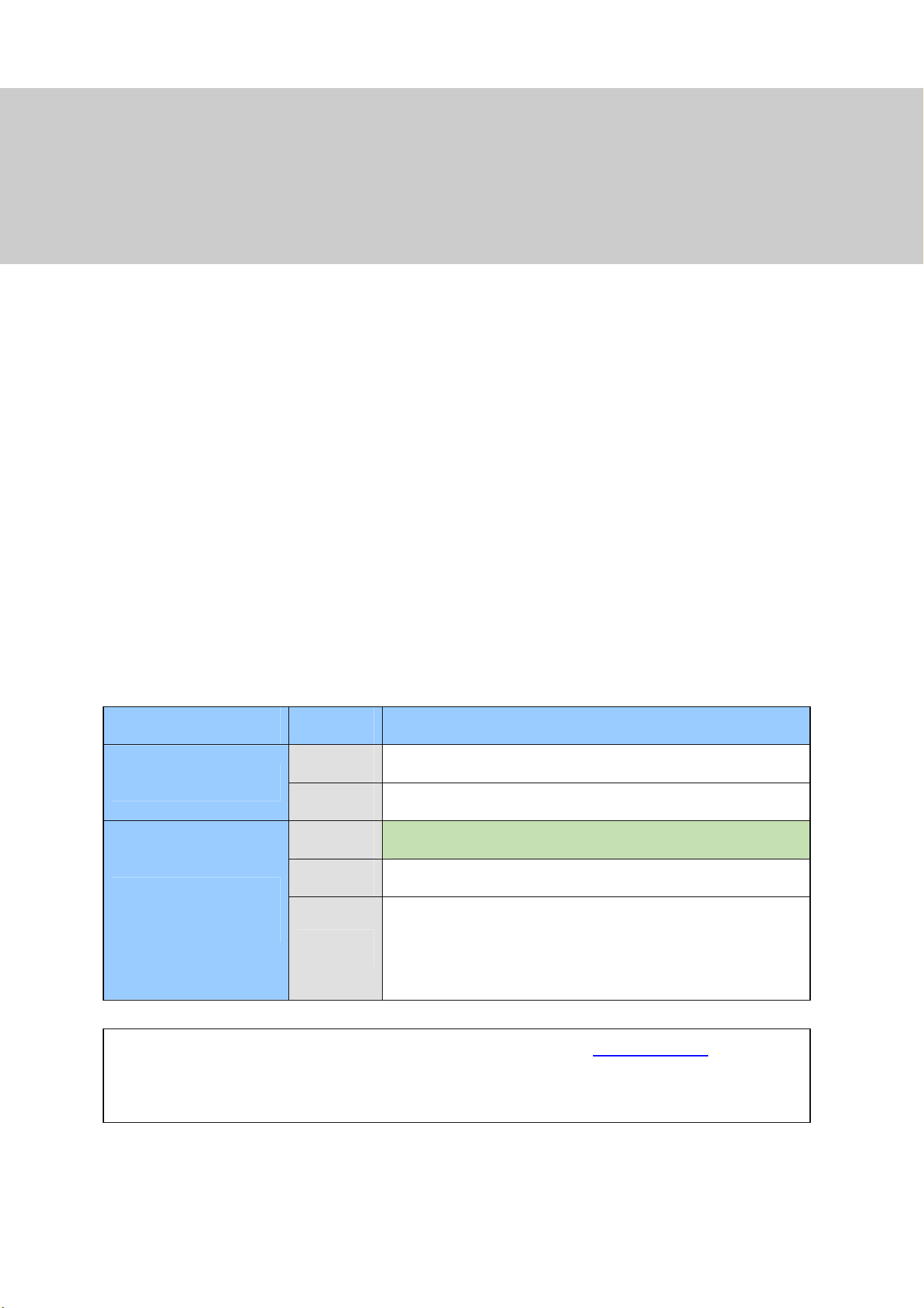
GV-VMS supports connection of up to 64 IP devices, with connecting up to 32 GV-IP devices for free. If
you need to connect more than 32 channels of GV-IP devices or connect with third-party IP devices,
licenses are required.
Supported Devices Channels License
32 ch No license required.
GV IP Devices Only
64 ch
GV-VMS Pro license required, 32 ch per license.
16 ch
Trial Version: 16 channels of 3
rd
party IP devices (60 days).
32 ch
3
rd
-Party or HD DVR license required, in increments of 1 ch.
GV + 3rd-Party IP
Devices
64 ch
2 licenses required:
GV-VMS Pro license, 32 ch per license.
3
rd
-Party or HD DVR license, in increments of 1 ch.
IMPORTANT: The licensing comes in two forms: GV-USB dongle and software license.
The two are
incompatible. If a GV-USB dongle is inserted on the computer with the system, remove it before
applying software licensing.
CHAPTER
1

4
Note:
1. GV-USB dongle comes in internal and external dongles. Internal dongle is recommended for the
Hardware Watchdog function, which restarts the PC when Windows crashes or freezes.
2. For details on upgrading GV-USB Dongle, see Chapter 8 Dongle Upgrade in GV-VMS Quick
Start Guide.
Note for GV-VMS V17.4.5:
1. The HD DVR license is only supported by GV-VMS V17.4.5 now.
2. The HD DVR license is required for connecting UA-XVR and UA-XVL series (only analog
channels supported)
3. The 3
rd
-party license is required for connecting UA-IP cameras.
1.1.2 Minimum System Requirements
GV-VMS (Up to 32 Channels)
GV-VMS Pro (Up to 64 Channels)
OS
64-bit Windows 7 / 8 / 8.1 / 10 / 11 / Server 2008 R2 / Server 2012 R2 /
Server 2016 / Server 2019
CPU
4th Generation i5-4670, 3.4 GHz
4th Generation i7-4770, 3.4 GHz
Memory
8 GB RAM
16 GB RAM
Processor Graphics
To obtain the maximum frame rate possible, see GPU Decoding
Specifications at the beginning of the manual.
Note:
1. To use the fisheye dewarping function, the graphic card must support DirectX 10.1 or above.
2. H.265 decoding requires 6th Generation Intel Desktop Processor (Skylake) or above, which
comes with onboard GPU.
3. The system requirements are determined in round-the-clock recording settings with live view
only, while remote connections and video analysis features being disabled.
4. To save system logs using Microsoft SQL Server, Microsoft SQL Server 2014 Express or later is
required.

Configuring Main System
5
1
1.1.3 Options
For the following optional devices of GV-VMS, contact your dealer for more information.
Optional Devices Description
GV-COM V3
GV-COM V3 can add 1 RS-232 / RS-485 serial port through the
GV-VMS’ USB port.
GV-IR Remote Control
GV-IR Remote Control allows you to control GV-VMS at the maximum
operation distance of 7 m (22.97 ft).
GV-IO Box Series
GV-IO Box series provides 4 / 8 / 16 inputs and relay outputs, and
supports both DC and AC output voltages, with optional support for
Ethernet module and 4E additionally supporting PoE connection.
GV-Joystick V2
GV-Joystick V2 allows you to easily control PTZ cameras. It can be
either plugged into GV-VMS for independent use or connected to
GV-Keyboard.
GV-Keyboard V3
GV-Keyboard V3 is used to program and operate GV-VMS and PTZ
cameras with keyboard and function keys. Through RS-485
configuration, it can control up to 36 GV-VMS. In addition, you can
connect PTZ cameras directly to the keyboard for PTZ control.
GV-NET I/O Card V3.2
GV-NET/IO card V3.2 provides 4 inputs and 4 relay outputs. It supports
both DC and AC output voltages and provides a USB port as well.

6
1.1.4 Minimum Network Requirements
The data transmitting capacity of GV-VMS depends on the number of Gigabit connections available.
The numbers of Gigabit network cards required to connect 64 channels are listed below according to
the resolution and codec of the source video.
Codec Resolution
Bitrate Used
(Mbps)
Total FPS
for 64 ch
Gigabit Network
Cards Required
Max. Channels Supported
per Network Card
1.3 MP
5.05 1920 1 Max. 64 ch / card
2 MP
7.01 1920 1 Max. 64 ch / card
3 MP
10.48 1280 1 Max. 64 ch / card
4 MP
11.65 960 2 Max. 50 ch / card
5 MP
16.48 640 2 Max. 38 ch / card
8 MP
17.14 1600 2 Max. 38 ch / card.
H.264
12 MP
16.67 960 2 Max. 38 ch / card
3 MP
7.06 1920 1 Max. 64 ch / card
4 MP
9.44 1600 1 Max. 64 ch / card
H.265
5 MP
7.52 1920 1 Max. 64 ch / card
1.3 MP
32.36 1920 3 Max. 22 ch / card
2 MP
44.96 1920 4 Max. 16 ch / card
3 MP
38.73 1280 4 Max. 18 ch / card
4 MP
40.35 960 4 Max. 17 ch / card
5 MP
30.48 640 3 Max. 22 ch / card
8 MP
58.52 1600 6 Max. 12 ch / card
MJPEG
12 MP
65.98 960 6 Max. 11 ch / card
Note: The network requirements may vary depending on the bit rate of the streams.

Configuring Main System
7
1
1.1.5 Installing GV-VMS
Before You Start
For optimal performance, please refer to the following recommendations before installing GV-VMS:
It is highly recommended to use separate hard disks; one for installing Windows OS and GV-VMS
software, while the other for storing recorded files and system logs.
When formatting the hard disks, select NTFS as the file system.
When GV-VMS is running, it is not recommended to perform disk defragmentation at the same
time.
Since the size of transmitted data from IP cameras may be quite large and reach beyond the
transfer rate of a hard disk, you should note the total of recording frame rates that you can assign
to a single hard disk when single-stream (Main or Sub stream) recording is applied, as listed
below:
Frame rate limit in a single hard disk with single-stream recording applied
H.264 H.265
Video Resolution
Frame Rate
(fps)
Bit Rate
(Mbit/s)
Frame Rate
(fps)
Bit Rate
(Mbit/s)
1.3 MP (1280 x 1024) 660 5.05 N/A N/A
2 MP (1920 x 1080) 660 7.01 N/A N/A
3 MP (2048 x 1536) 440 10.48 660 5.35
4 MP (2048 x 1944) 330 11.65 550 7.74
5 MP (2560 x 1920) 220 16.48 660 6.73
8 MP (3840 x 2120) 550 14.13 N/A N/A
12 MP (4000 x 3000) 330 14.47 N/A N/A
Note: The data above was determined using the bitrate listed above, hard disks with average
R/W speed above 110 MB/s, and with single-stream recording (Main or Sub stream) recording is
applied.
Recording Main and Sub streams together will require significantly more hard drive space than
single-stream recording. When single- stream (either Main or Sub stream) recording is applied, up to
22 channels can be assigned to one hard disk. But when dual-stream (Main and Sub streams)
recording is enabled, only up to 11 channels can be recorded to one hard disk.
The frame rate limit is based on the resolution of video sources. The higher the resolutions, the lower
the frame rates you can assign to a single hard disk. In other words, the higher the frame rates you
wish to record, the more hard disks you’ll need. For detailed information of recording frame rates, refer
to the user’s manual of the IP camera that you wish to connect to.

8
Installing GV-VMS
1. Download GV-VMS by selecting Primary Applications from the drop-down list and clicking
Download
of GV-VMS on GeoVision’s website.
2. If you are using a USB dongle, insert the dongle to your computer. See 1.1.1 Dongle for
connections requiring dongle license(s).
3. To install USB driver, select Drivers, F/W, Patch from the drop-down list, and click Download icon
of GV-Series Card Driver / USB Devices Driver.
To verify the driver is installed correctly, go to Windows Device Manager and expand
DVR-Devices. You should see GV-Series USB Protector.
Figure 1-1
1.2 Getting Started
When you run GV-VMS for the first time, the system will prompt you for a Supervisor ID and Password.
1. Type the desired ID, Password and a Hint to remind you of the password.
2. Optionally set up the following functions
E-Mail List: Enter e-mail addresses used to receive the password when forgotten.
Auto Login: Allows auto login as the current user every time when the system is launched.
Allow removing password System: It is recommended to select this option allowing
removal of the password database once you forget passwords. For details, see the same
option in Account and Password later in this chapter.
: Click to open the onscreen keyboard to enter the login information.
3. Click OK. The main screen of GV-VMS and a dialog box appears.
4. To choose how to save your system database, select Microsoft Office Access Database or
Microsoft SQL Server and fill out the required fields.
5. Upon first-time starting of GV-VMS, you are prompted with the Automatic Setup dialog box to
assist you in quickly adding IP devices to GV-VMS.

Configuring Main System
9
1
1.2.1 Main Screen
Home
ViewLog
ToolbarLogin ID
Exit
Storage Space
Version Information
Audio
Figure 1-2
Name Description
Login ID Click to manage accounts and passwords for accessing GV-VMS.
Audio Click to control the volume of your PC.
Home Shows the live view of connected cameras.
ViewLog Shows a timeline of recorded events for playback.
Toolbar
Brings up these options when Home is selected:
Monitor: Start / Stop monitoring, I/O monitoring and schedule monitoring
Network: Enable Webcam Server and connection to other GeoVision software.
Tools: Show / hide volume indicator and set up Object Index.
Configure: Set up camera, recording, system, schedule, video processing and I/O
devices.
Content List: Access live view layout, camera and I/O device lists and panorama view.
Brings up these options when ViewLog is selected:

10
Display Play Panel: Display or hide the ViewLog timeline. This function is grayed out
when the Pinned button is selected in the bottom-right corner.
Tools: Manage event search, system log, event backup and event export.
Configure: Apply video effects and text overlay during playback.
Content List: Manage playback layout and access camera list.
Exit Click to minimize or exit GV-VMS.
1.2.2 Adding Cameras
To add cameras to GV-VMS, click Home > Toolbar > Configure > Camera Install.
When the camera list is empty, the Automatic Setup dialog box automatically pops up.
Click Automatic Setup to search for IP cameras on the LAN. Then select / deselect the desired
cameras listed and click Apply.
Figure 1-3
Note:
1. The default login ID and password of connected cameras is admin / admin. To specify a login
credential, double-click the camera. If you select Apply All, the login info will be applied to all
selected cameras.
2. When cameras are added for the first time, they are automatically assigned to the live view grid.
To manually add cameras, see Adding IP Cameras in Chapter 2.

Configuring Main System
11
1
1.2.3 Accessing Live View
After adding cameras, you can access camera live view by dragging the camera in the Content List to
the live view grid.
Click Home
> Toolbar > Content List . Then click Camera in the content list to see
the list of cameras added, and drag the desired cameras to the live view grid.
Figure 1-4
See Live View and Layouts later in this chapter for details.
1.2.4 Enabling Recording
To start recording, click Home > Toolbar > Monitor > Start All Monitoring.
Alternatively, select the cameras you want to start monitoring.
By default, every camera records with the following settings:
Default Recording Settings
Recording Mode Motion Detection
Resolution / Codec The camera’s current resolution / codec will be used.
To change recording mode, see Recording Settings later in this chapter.
To change resolution and codec, see Configuring Video Setting in Chapter 2.
12
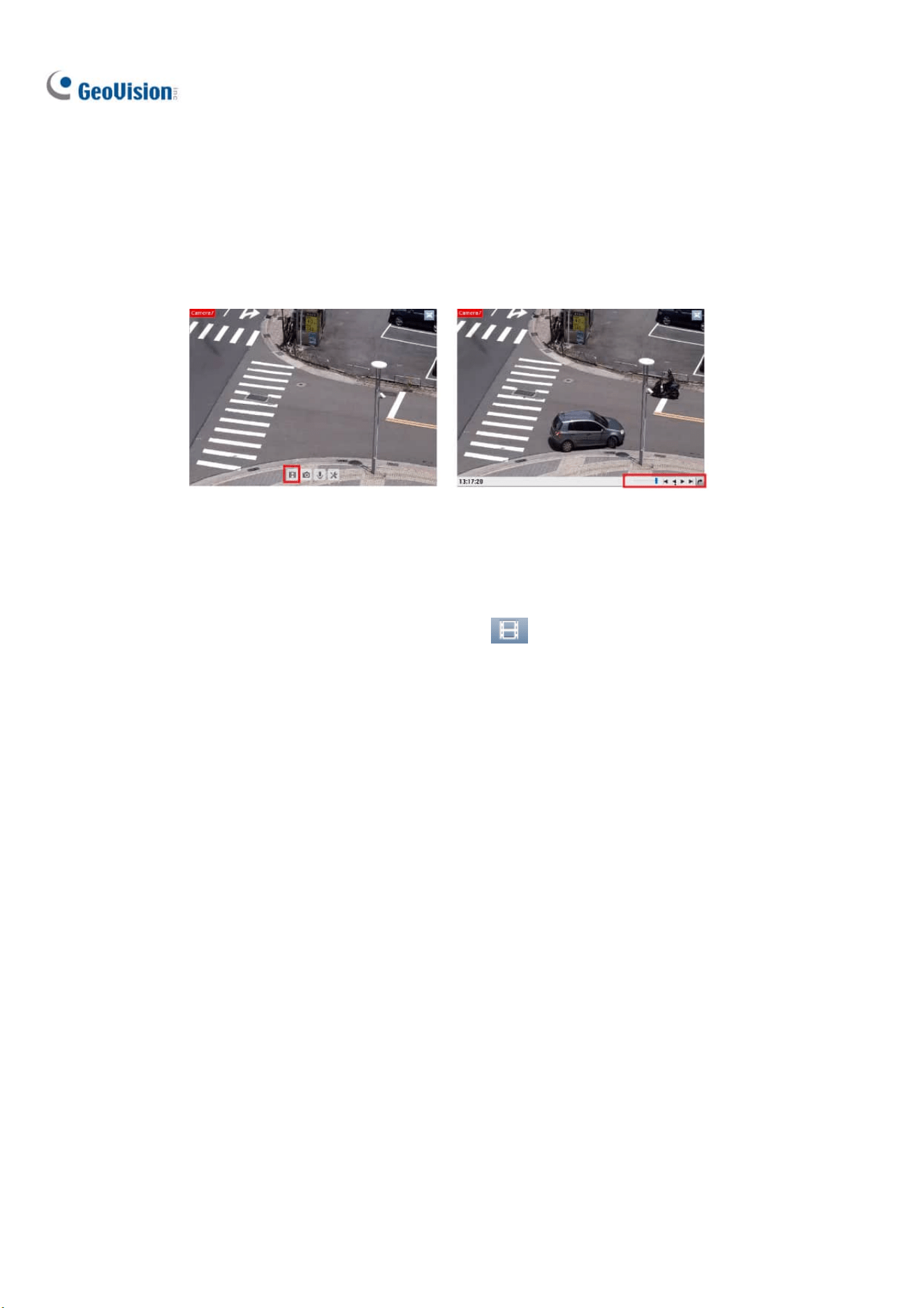
1.2.5 Playing Back Video
Instant Playback
You can instantly play back the recorded video of a single camera from the camera live view by clicking
the Instant Playback button.
Figure 1-5
ViewLog
For comprehensive playback functions, click ViewLog on the top-right corner.
For details, see Video Playback in Chapter 4.
Configuring Main System
13
1
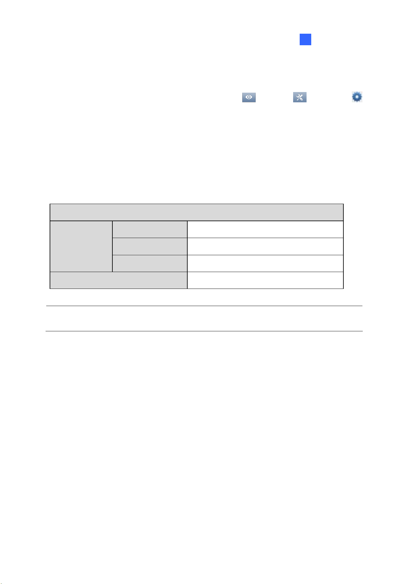
1.3 Recording Settings
To configure the recording setting of the cameras, click Home > Toolbar > Configure
> System Configure > Record Setting. The Recording Setting dialog allows you to configure the
following settings:
1.3.1 Setting up Global Recording Settings for All Cameras
1.3.2 Setting up Recording Settings for Individual Cameras
1.3.4 Setting up Motion Detection
By default, the system has the following recording storage settings.
Default Data Storage Settings
Recorded Files D:\Record\<camxx or audxx folder>.
Event Database Files C:\GV-VMS\CameraDBs\
Storage Location
Storyline Files C:\GV-VMS\StoryLine\
Recycle Function Enabled with recycling threshold set to 32 G.
Note: A storage folder is created automatically upon assigning the camera ID. For example, camera
of ID 1 will be saved in the folder D:\Record\Cam01.
14
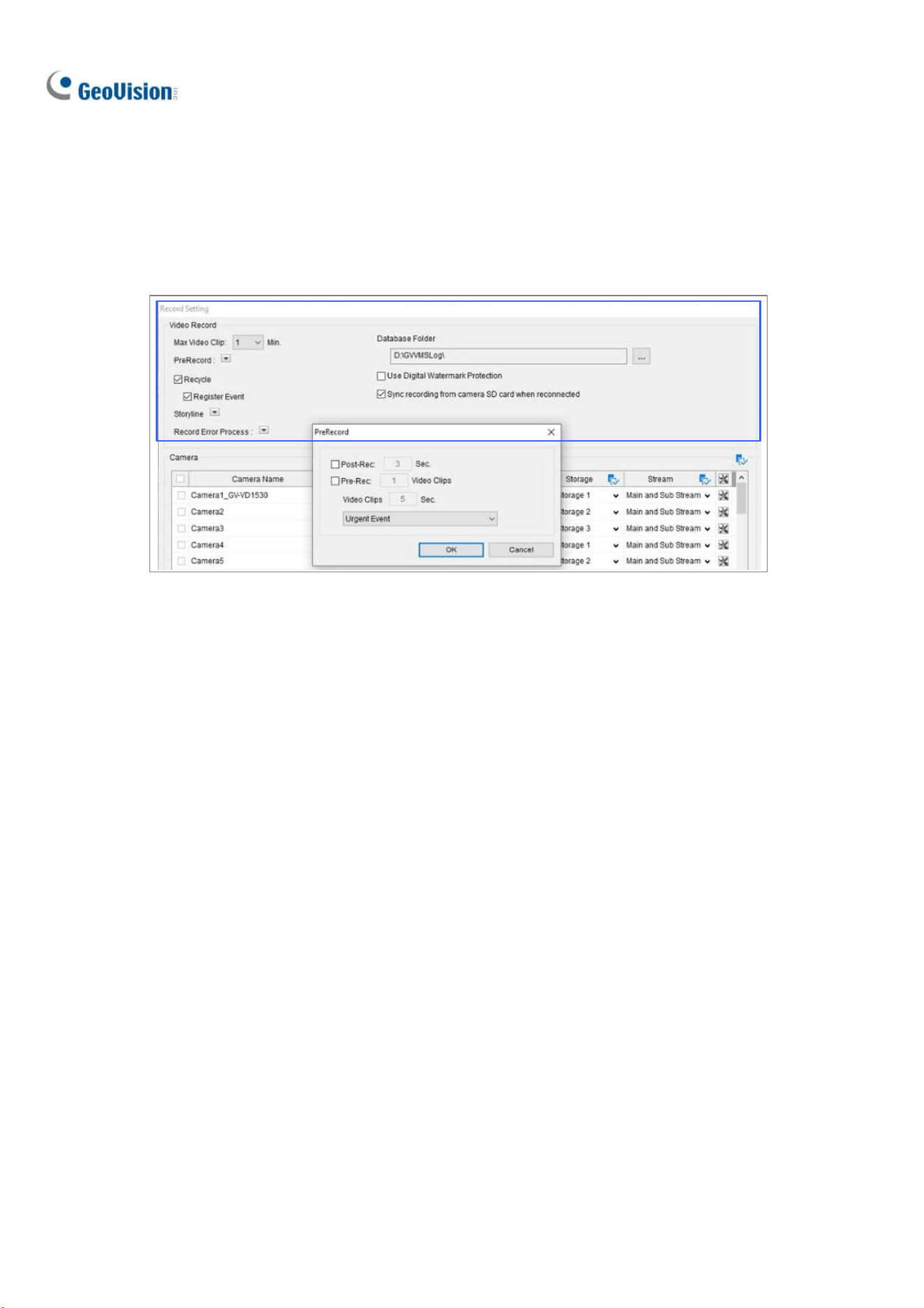
1.3.1 Setting up Global Recording Settings for All Cameras
You can configure global recording settings to be applied to all cameras, such as maximum length of
each video clip, recycling function and the actions to take upon recording errors.
Figure 1-6
[Video Record]
Max Video Clip: Specifies the maximum time length of each recorded file (from 1 to 5 minutes),
i.e. if you select 5 Min, a 30-minute event will be chopped into six 5-minute event files.
Post-Rec: Keeps on recording for a set period of time after an event stops. Click the button next to
Pre-Record to access.
Pre-Rec: Records video for a set period of time before an event starts. Specify the number of
video clips to pre-record and specify the number of seconds per video clip. For example, if you
specify 3 video clips and 5 seconds, 15 seconds of video, 3 files of 5 seconds each, before each
motion or input event will be recorded. Click the button next to PreRecord to access.
To set the frame rate for pre-recording, you can select Urgent Event or General Event. The frame
rate for General Event and Urgent Event can be defined in the camera’s Record Setting dialog box
(Figure 1-7). Normally, you would set a higher frame rate for Urgent Events (Ex: full frame) and a
lower frame rate for General Events (Ex: key frame only).
Recycle: When selected, the oldest recordings will be deleted when the system requires storage
space for new files. If not selected, the system will stop recording when disk space is full. Select
Register Event if you want to recycle Register Events from the System Log.

Configuring Main System
15
1
Sync recording from camera SD card when reconnected: Retrieves and restores recordings
from the SD cards of cameras selected when reconnecting after a temporary disconnection. After
enabling, select the cameras for this function to be applied to by checking the checkboxes beside
Camera Name. Recordings that are synced from the SD cards of recorded cameras are displayed
in yellow within the Timeline of ViewLog.
Figure 1-7
Note: This function is only supported by ONVIF cameras of Profile G conformant and the following
models of GV-IP cameras:
GV-BL2702 series / 3700 / 4702 / 4713 / 5700 / 5713
GV-BX2700 series / 2700-FD / 4700 series / 4700-E / 4700-FD / 5700 series
GV-EBL4702 series / EBL4711 / EDR4700 series / EFD4700 series
GV-EFER3700 / EFER3700-W / FER5700 / FER5701
GV-MFD2700 series / MFD4700 series
GV-VD2702 / 2712 / 3700 / 4702 / 4711 / 4712 / 5700 / 5711
Storage-supporting models of GV-ABL / AVD / EBD / TBL / TDR / TFD / TVD series
[Record Error Process] Define which actions to take when a recording error occurs.
Invoke Alarm: Activates computer alarm by playing the selected sound file.
Invoke to Send Alerts: Sends e-mail notifications. For details, see Setting up E-mail Notifications
later in this chapter.
Register Event: Records errors to the System Log.
Output Module: Triggers the selected output device. To configure output devices, see Chapter 6
I/O Applications to configure output devices.
[Storyline]
Keep Image Ratio: Keeps the image ratio of the recorded storyline videos.
Resolution: Specifies the resolution of the recorded storyline videos.

16
Path: The default storage path for Storyline is at C:\GV-VMS\ Storyline\. Click
to specify a
new storage path.
Note: To record a storyline, see Storyline later in this chapter.
[Database Folder]
The default storage path for Event Database (.db files) is at C:\GV-VMS\CameraDBs\. Click
to
specify a new storage path. Note that the storage path of recorded videos is specified in the Add Log
Location option. For details, see Setting up the Video Storage Location later in this chapter.
[Use Digital Watermark Protection] Watermarks all recordings. For details, see Watermark Viewer in
Chapter 9.

Configuring Main System
17
1
1.3.2 Setting up Recording Settings for Individual Cameras
You can configure the recording mode and video storage location for the selected cameras only.
Figure 1-8
1. Select the camera you want to configure. Hold the Shift key to select multiple cameras if needed.
2. Under Record Type, select Disable, Motion Detection or Round-the-Clock.
3. You can set different recording frame rates. Select Urgent Event to record in full frame rate.
Select General Event to record only the key frames.
The frame rate for General Event and Urgent Event can be defined in the camera’s General
Setting dialog box (Figure 2-13). Normally, you would set a higher frame rate for Urgent Events
(e.g. full frame) and a lower frame rate for General Events (e.g. key frame only).
4. If there are more than one storage locations, select Storage to specify where to store the
recordings. See Setting up the Video Storage Location later in this section.
5. Under Stream, select the stream(s) you want to record. By default, Main Stream is set to record
high-resolution video images. Select Sub Stream to record lower-resolution video images. Select
Main Stream and Sub Stream to record both streams simultaneously.

18
IMPORTANT: Recording Main and Sub streams together will require much larger hard drive space
than single-stream recording. When single- stream (either Main or Sub stream) recording is applied,
up to 22 channels can be assigned to one hard disk. But when dual-stream (Main and Sub streams)
recording is enabled, only up to 11 channels can be recorded to one hard disk.
Note:
1. Refer to Configuring General Settings in Chapter 2 for setting the frame rate for General Event
and Urgent Event.
2. In Round-the-Clock mode, for motion recordings, the Video Record Type setting in the
Advanced Motion Detection Setup dialog box has priority over the Video record frame rate
setting in the Record Setting dialog box (Figure 1-8). For example, if you select General Event
in the Record Setting dialog box, but select Urgent Event in the Advanced Motion Detection
Setup dialog box, the motion events will be recorded in full frame rate as Urgent Event.
See Setting up Motion Detection later in this section for details.

Configuring Main System
19
1
1.3.3 Setting up the Video Storage Location
Add Log Location
You can create a maximum of 24 storage groups with different storage locations. The default storage
location is D:\Record\.
1. On the Recording Setting dialog box (Figure 1-6), select a camera and click
next to Add Log
Location. This dialog box appears.
Figure 1-9
2. To add a new folder in the first storage group, click
above Path and select a folder. Only 1
folder can be assigned as storage folder per partition (e.g. only 1 folder in D drive).
3. To add a new storage group, click
in the top-left corner and repeat the step above to assign at
least one folder to the storage group.
4. Select Keep Days and specify the number of days to keep the video files in storage.
5. In the Enlarge Recycle Threshold field, adjust the recycle threshold (minimum 5 GB; maximum
999 GB) if needed. Recycle threshold is the file size at which the recycling begins.
6. To specify the actions to take when hard disks become full, click
next to Disk Full Process.
Invoke Alarm: Activates computer alarm by playing the selected sound file.
Invoke to Send Alerts: Sends e-mail notifications. For details, see Setting up E-mail
Notifications later in this chapter.

20
Register Event: Records errors to the System Log.
Output Module: Triggers the selected output device. To see how to set up I/O devices, refer
to Chapter 6 I/O Applications.
7. Click OK.
Note: If the designated storage space is not big enough to keep all video files for the defined days,
the Recycle Threshold setting will override the Keep Days setting.
Apply Partition to Record
GV-VMS can automate the configuration of recording paths for multiple camera channels. Each of your
cameras will be equally distributed to the assigned recording paths after you have set up the storage
locations.
1. On the Recording Setting dialog box, click Apply Partition to Record.
2. Select the desired recording paths (at least one) to store camera recordings and click OK.
1.3.4 Setting up Motion Detection
The motion detection settings will be applied to motion events in both Round-the-Clock mode and
Motion mode. The following features are available to prevent false motion detection:
Object Size: Set a minimum and maximum object size to only detect objects within the size
range
Sensitivity: Designate up to 10 levels of motion detection sensitivity for each outlined area
Mask Region: Mask off unwanted areas for monitoring, such as cloud and tree movement
Noise Tolerance: Ignore video noise when the lighting condition is poor or changed
Ignore environmental changes: Ignore changes such as rain, snow and tree movement
Minimum Duration: Set the minimum duration for which motions must persist for the system to
issue a motion alarm

Configuring Main System
21
1
1. Open the Recording Setting dialog box (Figure 1-6), select a camera and click . This dialog box
appears.
Figure 1-10
2. You can refine motion detection by setting either Object Size or Region Sensitivity.
◼ Define Object: Limit motion detection to objects within a size range. Select User-defined and
set the Min. Object Size and Max. Object Size in the respective drop-down lists.
◼ Set Region Sensitivity: Set different detection sensitivities for different parts of the camera
image. Uncheck User-defined, adjust the sensitivity level by moving the slider, and drag an
area on the image. You can create several areas with different sensitivity levels. You can use
the Add/Cut Mask buttons to create irregular shapes. By default, the entire
image is set to sensitivity level 9.
3. To ignore motion in specific areas of the image, click Mask Region, and drag areas on the image.
4. The following options are available to further reduce false alarm:
◼ Noise Tolerance: Enable to ignore video noise and move the slider to adjust the level. The
higher the level, the more tolerant the system is to video noise.
◼ Ignore environmental changes: Ignore environmental changes such as rain or snow. When
this option is selected, objects moving steadily and repeatedly in the same direction for over
1.5 seconds are filtered out and ignored.
◼ Minimum Duration: Set the minimum duration for which motions must persist for the system
to issue a motion alarm. Set the minimum duration in seconds (up to 60).

22
5. You can reduce CPU loading by selecting Process Video in Lower Resolution. When this option
is enabled, GV-VMS compresses live view into a lower resolution before GV-VMS detects if there
is motion, which reduces CPU loading, but may affect accuracy.
6. The camera’s built-in motion detection is enabled by default. To use GV-VSM software motion
detection instead of the camera’s, deselect Enable Camera’s Built-in Motion Detection.
Note: The camera’s built-in motion detection is enabled by default in GV-VMS V17.4 or later, with the
exception of GV-QSD series, GV-QFER series, and cameras connected through ONVIF, which use
software motion detection when connected.
7. To set the frame rate setting for motion events, click Video record frame rate and select Urgent
Event or General Event. Normally, you would set a higher frame rate for Urgent Events (Ex: full
frame) and select Urgent Event here for motion events. See Configuring General Setting in
Chapter 2 to modify the frame rates of general and urgent events.
8. Under Event Trigger, select the actions to take when motion is detected.
◼ E-mail: Send e-mail notifications. For details, see Setting up E-mail Notifications later in this
chapter.
◼ Output Module: See Chapter 6 I/O Applications for I/O device setup.
◼ Register Motion Event: Register motion events to the System Log.
◼ Invoke Alarm: Activate computer alarm by playing the selected sound file.
9. Click OK to save your settings.
Note:
1. You can only enable motion detection either by sensitivity or by object size at a time.
2. By default, the entire camera view is set to a motion sensitivity level of 9 with Noise Tolerance
and Process Video in Lower Resolution functions enabled.
Configuring Main System
23
1
1.4 Live View and Layouts
This section describes the functions on the camera live view and how to create new live view layouts.
1.4.1 Utilizing Live View Functions
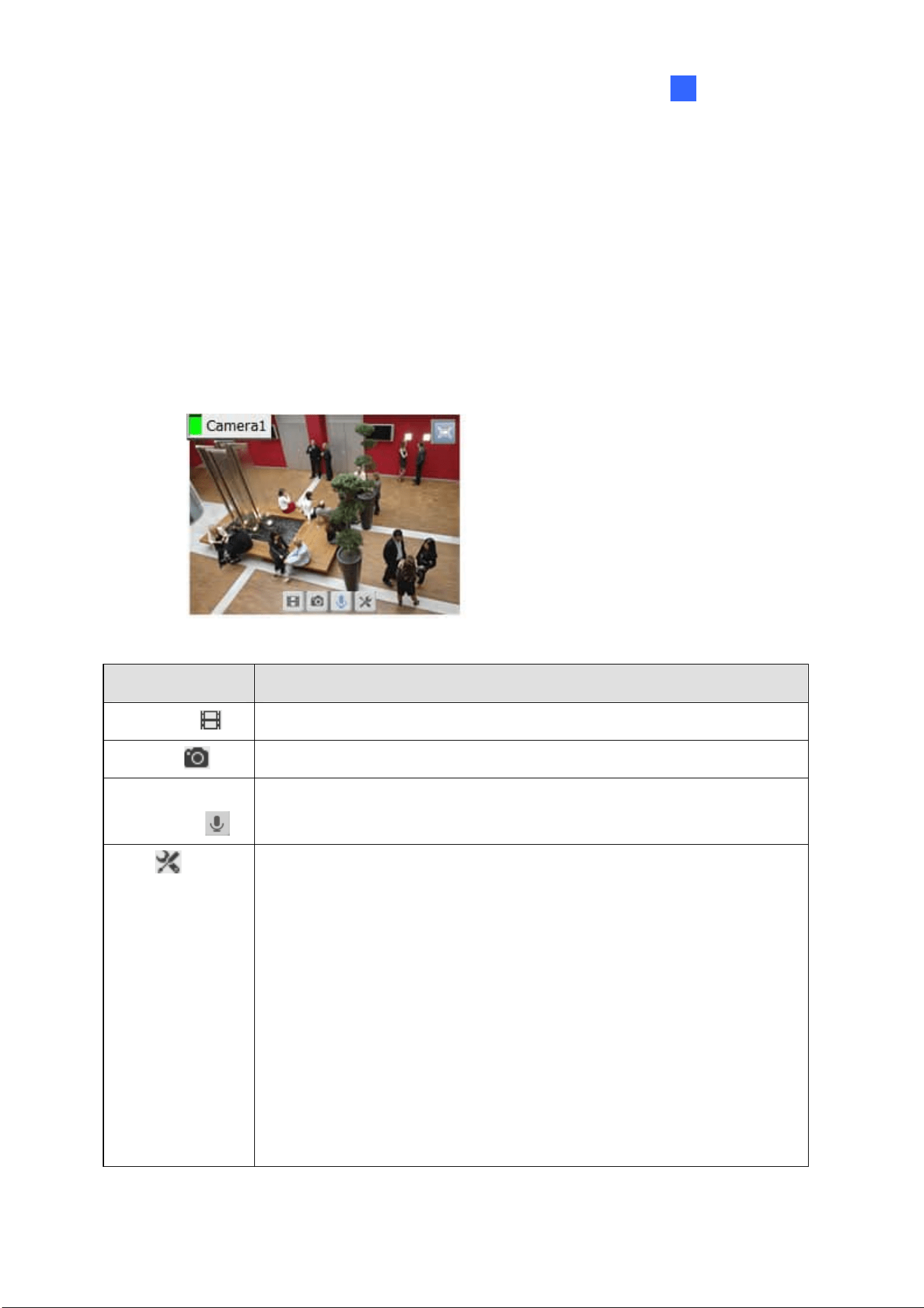
Live View Icons
Place the mouse cursor on the camera live view to see the icons below.
Figure 1-11
Icons Functions
Instant Play
Plays back the video recorded.
Snapshot
Captures a snapshot of the current live view.
Talk Back Toggle /
Push-to-Talk
Talk to the surveillance site. For details, refer to [The behavior of the talk back
button], Configuring General Settings later in this chapter.
Tools
Includes the following options:
Monitor: Starts monitoring the camera.
Properties:
Show Caption: Shows camera name on live view.
Keep Image Ratio: Locks aspect ratio of the camera image.
Close: Removes the camera from the layout grid.
The following options are available when related function is enabled or
supported:
Set to Wave Out: Enables live view audio. (See Configuring Audio
Setting, Chapter 2)
24
Tools
PTZ Control: Enables PTZ functions. (See PTZ Camera later in this chapter)
Add to bookmark: Bookmarks a scene to watch later in ViewLog player. The
function is only available when the channel is recording.
Storyline: Records a sequence of short video clips of a specific incident.
(See Storyline later in this chapter)
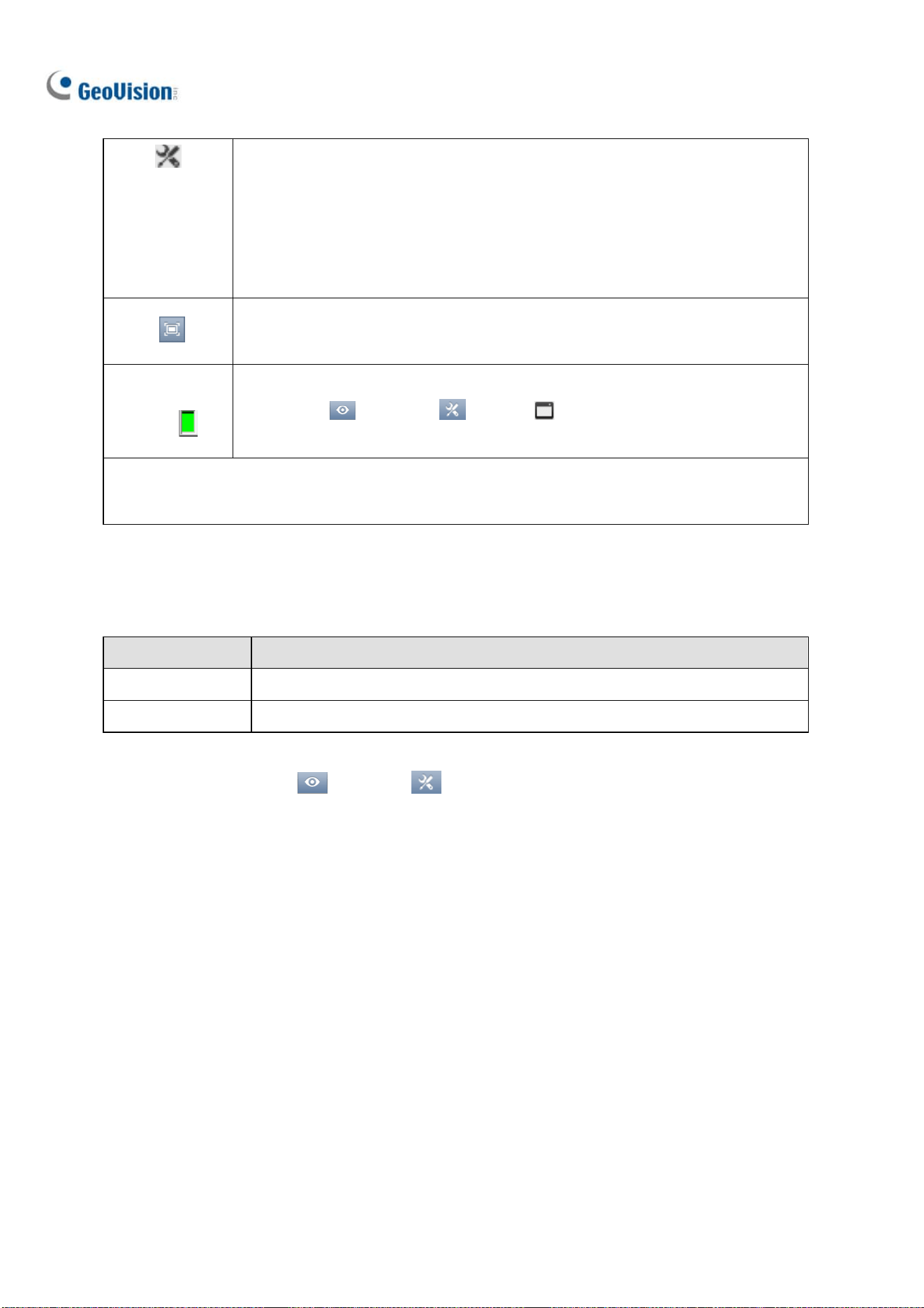
Zoom
Switches the live view to full screen. If there is a designated Zoom window,
clicking the Zoom button will display the live view in the zoom window instead.
Volume
Indicator
Display an audio volume indicator on the top-left corner of the camera live view.
Click Home
> Toolbar > Tools > Audio > Show Volume
Indicator.
Note: When PTZ Control is enabled on a PTZ camera, double-clicking the live view will make the
camera zoom in instead of switching to full screen.
Functions on Live View and Content List
The live view screen can be controlled using the actions below.
Actions Functions
Mouse scroll Zooms in or out on the live view.
Double-click Displays the live view in full screen.
In the Content List (Home
> Toolbar > Content List), right-click a camera to access the
following options, when enabled or supported:
Monitor: Starts monitoring the camera. (See Start Monitoring later in this section)
Video Process: Opens the Video Processing dialog box. (See Chapter 3 Video Analysis)
Set to Wave Out: Enables live view audio. (See Configuring Audio Setting, Chapter 2)
Talk Back Toggle: Talks to the surveillance site from the PC. (See Configuring Audio Setting,
Chapter 2)
Focus View Setup: Creates up to 7 closed-up views in a camera. (See Setting up Focus View
later in this section)
PTZ Setup: Enables PTZ functions. (See PTZ Camera later in this chapter)
Fisheye Settings: Opens the Fisheye Settings dialog box. (See Fisheye View, Chapter 3)

Configuring Main System
25
1
Audio Broadcasting
When necessary, the GV-VMS operator can broadcast audio to multiple cameras simultaneously with
the speaker function.
Note: This function is not supported by cameras connected through RTSP protocol.
1. Click Home
> Toolbar > Tools > Audio Broadcast. This window appears.
Figure 1-12
2. Click the Down arrow button to select the cameras you wish to broadcast audio to.
3. To start audio broadcasting, press and hold the Push to Broadcast button
while talking to
the microphone connected to the computer of GV-VMS.
1.4.2 Arranging Live View Layouts
1. In the Content List, click Layout.
Figure 1-13
2. To add a layout, click Add
and click Add Layout. The Add New Layout dialog box appears.
3. Name the new layout and select one of the three available methods under Layout Setup to define
a layout and click OK.
4. If you select Customize in the step above, the Customize Layout dialog box will appear.
a. Click Reset to specify a dimension for the grid if needed.

26
b. Select multiple squares and click Merge to create a larger square.
c. Click OK when you are done.
A message appears. Click Yes if you want to automatically assign the cameras to the new layout.
Tip: You can right-click a layout in the Content List to access other functions to arrange the layout.
1.4.3 Setting up Zoom Window
You can designate a Zoom Window to quickly see a close-up view of the camera image without
changing the rest of the live view layout.
Note:
1. Up to two Zoom Windows can be created on each live view layout.
2. When there are two Zoom Windows, GV-VMS will alternate between the first Zoom Window
and the second Zoom Window each time you click the Zoom button of a camera.
1. In the Content List, select Layout, click Windows and drag Zoom Window to a live view grid.
2. Move the mouse cursor to a camera live view and click Zoom
in the top-right corner. The
camera live view is displayed in the Zoom Window.
3. To remove the camera from the Zoom window, place the cursor on the live view, click Tools
and select Close. To change the live view grid back to a normal window, repeat this step again to
close the Zoom Window.

Configuring Main System
27
1
1.4.4 Setting up Scan Window
You can assign multiple cameras to a Scan Window, and each camera will be shown in sequence for
the Scan Interval specified.
Note: Up to four Scan Windows can be created on each live view layout.
1. In the Content List, select Layout, select Windows, and drag Scan Window to a live view grid.
2. Drag multiple cameras into the Scan Window.
Figure 1-14
3. Move the cursor to the Scan Window, click Tools
, and select Properties. This dialog box
appears.

28
Figure 1-15
4. To adjust the order of a camera, select a camera and click the Up
and Down arrows.
5. To specify how many seconds to show the live view of each camera, click and adjust the Scan
Interval of each camera. Optionally click the Finger
to apply this Scan Interval to all
cameras.
6. To show camera name on live view, select Show Caption.
7. To lock the original aspect ratio of the camera image, select Keep Image Ratio.
8. Click OK.
1.4.4.1 Creating a Camera Group
You can also add multiple cameras to a group and the created group can be dragged into a live view
grid directly or Scan Window for display. At least 8 cameras are required in the camera list for this
function to work.
1. Click Camera in the Content List, click Add , and click Add Group. Rename the group if
necessary.
2. Drag the desired cameras from the camera list to the group created.
3. Drag the created group either into a live grid or Scan Window. For details on setting up Scan
Window, see Setting up Scan Window earlier in this chapter.

Configuring Main System
29
1
1.4.5 Setting up Popup Window
You can designate a Popup Window to display live images of cameras, upon events, on a separate
monitor. For this function to work, you must first create a live view layout on another monitor.
1. In the Content List, click Layout > Add
> Add Layout to create a new layout.
2. After clicking OK, select a desired monitor from the Apply to… list to activate the layout on the
designated monitor.
3. In the Content List, click Windows > Add
> Add camera popup window to select the
cameras to be displayed in the Popup Window.
Note: For details on configuring the Camera Popup Setting, see Popping up Live View later in this
chapter.
4. Rename the Popup Window if necessary and drag the Popup Window from the Content List to the
layout created in Step 3.
1.4.6 Setting up Focus View
You can create up to 7 close-up views per camera and place these created close-up views inside the
live view grid.
1. In the Content List, right-click a camera and select Focus View Setup. This dialog box appears.
Figure 1-16

30
2. Click Enable and draw a box on the camera view to create a focus view. You can create multiple
focus views if needed.
3. You can change the color of the box if needed.
4. Click OK. The created focus views are listed under the camera.
5. You can now drag the focus views to live view grids.
Note: This function is not supported for Fisheye Cameras and PTZ Cameras.
1.4.7 Automatic Switch among Different Live View Layouts
You can have different layouts automatically alternated at a specified interval.
1. Create and group several layout templates under the Content List (Figure 1-17).
2. Right-click the group to configure its Scan Setting to specify the scan interval.
Figure 1-17
To start the automatic switch, right-click the group and select Scan Start. In the example above,
Layout 1, Layout 2, and Layout 3 are automatically switched among each other every 10 seconds, with
the currently displayed layout highlighted in orange.

Configuring Main System
31
1
1.5 Start Monitoring
After setting up the following functions, it is important to start monitoring in order for the functions to
start: Recording, Video Analysis, Motion Event Trigger and Schedule.
To start monitoring, click Home
> Toolbar > Monitor and select one of the options:
Figure 1-18
Start Schedule Monitoring: If you want to start running a created schedule, select Start
Schedule Monitoring. The schedule takes precedence over the current settings, and these
functions will start and stop according to the schedule: Recording, Video Analysis, I/O, PTZ Auto
Functions, Motion Event Trigger and Network Connections with Center V2 / Vital Sign Monitor. For
details on creating a schedule, see Schedule later in this chapter.
Start All Monitoring: Starts monitoring on all cameras to initiate recording and related functions.
I/O Monitoring: Starts I/O monitoring to activate I/O functions. I/O Monitoring is only available
after at least one I/O device is set up. For details on setting an I/O device on GV-VMS, see Setting
up I/O Devices in Chapter 6.
Camera#: Starts monitoring of selected cameras. You can also start monitoring individual
cameras by right-clicking the camera in the Content List and select Monitor.
Note: Motion detection and I/O trigger will only be registered in the System Log if monitoring is
started. You will also need to enable Register Motion Event in the Advanced Motion Detection
Setup dialog box (Figure 1-10) and Register Input Event in the I/O Application Setting (Figure 6-10).

32
1.6 System Configuration
This section introduces system configurations of GV-VMS.
1.6.1 Configuring General Setting
Start configuring General Setting by clicking Home > Toolbar > Configure >
System Configure > General Setting. This dialog box appears.
Figure 1-20
[Location Name] The given name (maximum 14 characters) is displayed in the main screen as the
name of the server.
[Monitor Option]
Start Delay: Start recording x second(s) after Start All Monitoring or Start I/O Monitoring is
selected.
Service Mode: Under Service Mode, GV-VMS can start automatically after system startup and
run in the background without logging into Windows.

Configuring Main System
33
1
[Display]
Enable DirectDraw Scale: Applies DirectDraw Scale to enhance image quality if it is supported
by your VGA card. For certain VGA cards, DirectDraw Scale can result in blurred images. To avoid
the image problem and maintain DirectDraw Scale, change the image quality to Standard [Video
Setting] of the camera (Figure 2-11).
Note: The Enable Directdraw Scale function can greatly enhance image quality. Enable if your VGA
card supports DirectX9. To check the version of your DirectX, click Start and run dxdiag. Open the
file and find the related information.
[The behavior of the talk back button]
Talk Back Toggle: Users can click the
button to talk to the surveillance site and click the
button again to stop talking on the live view.
Push to talk: Users can click and hold the
button to talk to the surveillance site and release
the button to stop talking on the live view.
[Zoom Camera]
Auto enable wave out: Automatically enables Wave Out function of the camera in Zoom Window
or in full screen. Note that the Wave Out function needs to be enabled in the Audio Setting page of
the camera first.
Auto toggle talk back: Automatically enables Toggle Talk Back function of the camera. Note that
the Toggle Talk Back function needs to be enabled in the Audio Setting page of the camera first.
Auto switch PTZ mapping: This function only applies to GV-Keyboard connected to GV-VMS.
When selected, PTZ control from GV-Keyboard will be applied to the mapped PTZ camera. When
not selected, GV-Keyboard can only control the first available PTZ camera.
[Exit Option]
Auto Restart Windows: Restarts Windows OS after exiting GV-VMS.
Auto Shut down Windows: Shuts down Windows OS after exiting GV-VMS.

34
1.6.2 Customizing Startup Settings
To configure GV-VMS to enable certain features upon startup, click Home > Toolbar >
Configure
> System Configure > Startup. This dialog box appears.
Figure 1-21
[General]
Show Style: Change the color scheme of GV-VMS.
Auto Monitoring: Select one of the following monitor control modes upon startup:
Monitor All: Starts monitoring of all cameras and I/O (if available) upon system startup.
Schedule Monitor: Starts monitoring of cameras by schedule. See Schedule later in this
chapter.
I/O Monitor: Starts monitoring of all I/O devices upon startup.
Camera Monitor: Enables all cameras for monitoring.
Auto Run when Windows Starts: Automatically runs GV-VMS after Windows starts. If you did not
set an Auto Login account or an Auto Startup Login account, the Login dialog box will appear upon
startup.
Startup and Hide into System Tray: GV-VMS appears in the system tray when you launch
Windows instead of displaying the system login window.
Note: Startup and Hide into System Tray and Auto Startup Login cannot function at the same
time. When both are enabled, Auto Startup Login will not be applied. For details on Auto Startup
Login, see Setting up a Startup Auto Login User later in this chapter.

Configuring Main System
35
1
[Advanced]
GPU Decode: Enabled by default, GPU (Graphics Processing Unit) decoding lowers CPU loading
and increases the total frame rate supported by GV-VMS. But if your PC does not meet the system
requirements as listed in GPU Decoding at the beginning of the manual, you can disable this
function to optimize system operations. After deselecting GPU Decode, restart GV-VMS for the
change to take effect.
[Network]
Automatically enables connection to the following application(s) upon startup: WebCam Server,
Mobile Service, Center V2, VSM, GV-Cloud Center, Backup Center, Control Center Server
1.6.3 Customizing Display Position and Panel Resolution
You can customize the display settings of GV-VMS by clicking Home > Toolbar >
Configure
> System Configure > Set Position. This dialog box appears. The right half is only
available when multiple monitors are installed.
Figure 1-22
Select Monitor: Select the monitor you want to configure from the drop-down list.

36
Position: Offsets the position of the GV-VMS window relative to the upper-left corner of the
screen. The default position is 0, 0. A position of 100, 60 will place the GV-VMS window 100 pixels
to the right and 60 pixels below the upper-left corner. This function is only supported when the
GV-VMS window does not take up the entire screen.
Figure 1-23
Panel Resolution: Sets the Panel Resolution of GV-VMS.
1.6.4 Setting up E-mail Notifications
Events that can be used to trigger e-mail notifications include: Video Lost, Recording Error, Disk Full,
Motion Detection, I/O Trigger, Intruder Event, Crowd Detection, Advanced Unattended Object,
Advanced Scene Change Detection, Advanced Missing Object and Face Detection.
1. To receive e-mail notifications upon the occurrence of an event, click Home
> Toolbar
> Configure
> System Configure > Send Alerts Approach Setup. The Alert Approach
dialog box appears.
2. To enable e-mail notifications, select Send Email > Email Setup. This dialog box appears.
Figure 1-24
Configuring Main System
37
1
3. Under Mail Setup, type the host name of your outgoing mail server (SMTP), the sender’s e-mail
address, recipients’ e-mail addresses and a subject for the e-mail notification. For multiple
recipients, add a semicolon between each e-mail address.
4. Click the Test Mail button to send a test e-mail and see whether the setup is correct. If the e-mail
fails to send, you may need to check the following settings:
SMTP Mail Server requires authentication: If the SMTP mail server needs authentication for
login, select this option and type your account name and password.
SMTP Server: Keep the default port 25 which is common for most SMTP servers. However
webmail providers such as Gmail, Yahoo, and Hotmail generally use different SMTP port. In
this case, check your e-mail provider for the SMTP port number. Select SSL or TLS if your
e-mail server requires the SSL/TLS authentication for connection.
5. Complete other optional settings as needed:
Mail Content: Type the e-mail content that will be included in all e-mail notificaitons.
Attach Image Setup: Select Attach to include up to 6 snapshots in the e-mail. The image
format and size are selectable. Note the actual size can be either the main stream or the sub
stream depending on the On Demand setting. For details, see the On Demand Display section
later in this chapter.
Email-Alerts Interval: Specify the time interval (0-60 seconds) between e-mail alerts to
prevent e-mails from being sent too frequently. The default interval is 5 minutes.
Domain Name from DDNS: This option generates URL links for remote video playback in the
sent e-mails. For this function to work, enter the fixed IP address or domain name of
GV-VMS and enable WebCam Server.
E-mail in Text Mode: When WebCam Server is enabled, your e-mail alert will be sent in
HTML format. If you want to send the e-mail alert in pure text format, select this option.
Note: To enable WebCam Server, click Home
> Toolbar > Network > WebCam
Server.

38
1.6.5 System Idle Protection
The System Idle Protection automatically log off and/or start monitoring after GV-VMS is idle for a set
period of time.
1. Click Home
> Toolbar > Configure > System Configure > System Idle
Protection Setting. This dialog box appears.
Figure 1-25
2. To automatically log out or switch to Startup Auto Login User, select Auto Logout or Switch to
Startup Login User if available and select the type of account to log out from the drop-down list.
If you have set up a Startup Auto Login User, GV-VMS will switch to the Startup Login User instead
of logging out. For details, see Setting up a Startup Auto Login User later in this chapter.
3. To automatically start monitoring, select Auto Monitoring, and use the drop-down list to select
Monitoring All, Schedule Monitoring, I/O Monitoring or Camera Monitoring. When Monitoring
All is selected, both I/O Monitoring and Camera Monitoring will be enabled.
Select Auto Network Service of Startup Setting to enable network connections to the
applications predefined in Startup. See Customizing Startup Settings earlier in this chapter.
4. In the System Idle Over field, type an idle time between 10 and 14400 seconds.
5. Click OK.
Note: The feature can monitor keystrokes, mouse clicks and actions from IR Remote Control and
GV-Keyboard.

Configuring Main System
39
1
1.6.6 Configuring Fast Key Lock
1. To enable/disable certain fast keys, click Home > Toolbar > Configure > System
Configure > Fast Key Lock Setup. The Fast Key Lock Setup dialog box appears.
2. Select one of the four tabs: General, ViewLog, PTZ Control and Network.
3. Clear the checkmark for the fast keys you want to disable. To restore the fast keys, select the
checkbox again.
4. Click OK to apply your settings.
1.7 Account and Password
The password setup allows you to assign permission and rights to accounts. You can create up to
1,000 passwords. Only Supervisor-level accounts are pre-set with access to password settings. Click
the account ID, click Password Setup, and select Local Account Edit to start.
Figure 1-26
1.7.1 Creating an Account
To create a new account, click the New button at the lower-left hand corner of the Local Account Edit
dialog box. You can create three types of accounts Supervisor, Power User and User.
Supervisors have permissions over all system settings.
Power Users have the same permissions as Supervisors, except that they cannot edit user
accounts and delete the password system (described later).
Users are restricted from all system settings and have limited access to certain functions.
If you want to enable the guest account, click Guest and deselect the Disable Account option. Guests
will only be allowed to watch live view.

40
1.7.2 Configuring Account Settings
You may find these options to the right of the account list depending on the authorization level.
Figure 1-27
Disable Account: Select if you want to disable this account.
Time Setting: The account will expire and be disabled automatically after a set number of days.
Click Time Setting, and select Expire in (days). Specify the number between 1 and 9999.The
number you set will count down automatically.
Card Number Field: Users are allowed to automatically log into their accounts by inserting the
card in GV-PCR310 Enrollment Reader. Manually type your card number in the field, or insert your
card in GV-PCR310 Enrollment Reader and the card number will be shown in the field
automatically. Click
to attach the card number to the user account.
User cannot change password: The user is not allowed to change the set password.
Force password change at next login: The user must change the password at next login.
Disable account if user does not login after xx day (s): When the user does not log in the
system after a set number of days, its account will be disabled automatically.
Export this ID for IR Remote Control: Allows you to log into the system by using GV-Keyboard
instead of using the general keyboard and mouse. For details see GV-Keyboard User’s Manual.
Send password by Email: Allows you to retrieve passwords through e-mails. To specify e-mails,
click the […] button. See Changing or Retrieving Password at Login later in this chapter.
Login this ID automatically (Single User Mode): GV-VMS will automatically log into this account
after you click Login at startup.
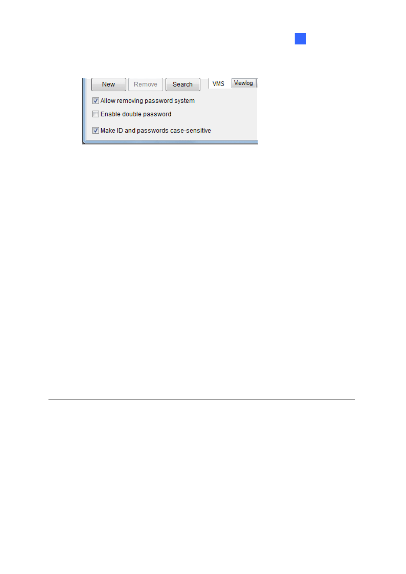
Configuring Main System
41
1
At the bottom of the page are global settings, which are applied to all accounts.
Figure 1-28
Allow removing password System: Enables the password removal utility. The option is critical if
you forget or are unable to retrieve any Supervisor password. With this option selected, you can
run the password removal utility PassUNINStall.exe from the GV folder and remove the password
database. Otherwise, you can only remove the password database by reinstalling Windows
operating system.
Enable double password: When selected, after starting ViewLog, you will need to type the
passwords of any two supervisors to continue. At least 2 supervisor accounts are required.
Make ID and passwords case-sensitive: Select to make all ID and passwords case-sensitive.
Note:
1. Before running the utility PassUNINStall.exe, you need to disable Service Mode on GV-VMS
(Figure 1-21) and close GV-VMS. After running the utility, restart GV-VMS.
2. The loss of passwords can be solved in the following two ways:
Retrieving password through e-mails.
Removing password database by using the PassUNINStall.exe utility and rebuilding all
accounts.
However, if both Send Password by Email and Allow Removing Password System options are
not selected in advance, it is required to reinstall Windows operating system once you lose the
passwords.

42
1.7.3 Changing or Retrieving Password at Login
You can change or retrieve passwords of GV-VMS through e-mail upon login.
Changing Password
1. In the Login dialog box, click Change Password. The Change Password dialog box appears.
2. Type the new password information, and click OK to save the changes.
Note: Only Supervisors can change the password.
Retrieving Password through E-mail
The password retrieval function works in the following ways after you click Send Password in the
Login dialog box.
If you are a supervisor but do not remember your ID, separate passwords will be sent to all
supervisor e-mail accounts after you click the Send Password button.
If you remember your ID but forgot your password, enter your ID and click Send Password. The
password will be sent to your e-mail account.
1.7.4 Preventing Unauthorized System Termination
1. To restrict a non-supervisor account from exiting or restarting the system, click the account ID,
click Password Setup, and select Local Account Edit. The Password Setup dialog box appears.
2. Select a user from the user list to display its properties.
3. Select the VMS tab at the bottom, and clear the Exit System option to restrict the user from
quitting or restarting the system.
Figure 1-29

Configuring Main System
43
1
1.7.5 Setting up a Startup Auto Login User
The Startup Auto Login User is typically a user account with limited access rights. After system is
started, GV-VMS will automatically log in with the Startup Auto Login User instead of showing the Login
dialog box.
1. Create an account you want to use for Startup Auto Login. Refer to Creating an Account earlier in
this section for instructions.
2. Click the account ID, click Password Setup, and select Startup Auto Login. Select Startup Auto
Login Setup.
3. Type the ID and Password of the existing account you want to use.
4. Click OK.
If you have selected Auto Logout or Switch to Startup Login User if available in System Idle
Protection Setting dialog box (Figure 1-25), GV-VMS will switch to the Auto Startup Login account after
it is idle for the set period of time.
1.7.6 Setting up Limits on Playback Time
1. To restrict playback time of camera channels, on the Local Account Edit dialog box, select a
account, click the ViewLog tab, and click the playback time column you wish to configure.
Figure 1-30
2. Select Limited Playback Time and specify a time limit. If you click
, the time limit will be
applied to other cameras.

44
1.8 Schedule
You can create schedules to enable and disable the following functions at specific times of a day and
apply the schedule to a weekly, monthly plan or a specific date.
Recording
Alert upon motion detection
PTZ object tracking
PTZ Auto functions
Video Processing
I/O monitoring
Network connections to Center V2, Vital Sign Monitor, WebCam Server, Mobile Service and
GV-Edge Recording Manager.
Click Home
> Toolbar > Configure > Schedule Edit. This dialog box appears.
Figure 1-31

Configuring Main System
45
1
1.8.1 Creating a Schedule with Setup Wizard
The Setup Wizard is an easy way to create new schedule.
1. In the Schedule dialog box, click Schedule and select Setup Wizard.
2. Specify when to apply the schedule plan and click Next.
Weekly: Applies the schedule plan to the selected days each week.
Special Day: Applies the schedule plan to a specific date.
Monthly: Applies the schedule plan to a specific day each month.
Note: You can apply the schedule plan to additional days or modify the time settings later. After the
schedule plan is created, refer to Step 3 in Creating a Schedule Manually later in this section.
3. Type a name for the schedule plan. If you have existing schedule plans, you can select Use
current plan and apply the selected plan to different days.
Figure 1-32
4. Click Next. This dialog box appears.
Figure 1-33

46
5. When the Include button
is selected, you will start with an empty timeline. Click the Add
button and drag across the timeline when you want the function to be enabled. Use the
Erase button when you want to disable the function.
6. You can also click the Exclude button and start with everything disabled. The Add button
is now used for disabling the function instead and the Erase button is now used for
enabling the function.
7. Four categories are available on the left.
Camera:
Round-the-Clock Recording: When highlighting the timeline, you can choose to apply
the frame rate settings for General Event or Urgent Event. The settings here will
override the settings in Record Setting once schedule monitoring is started. For
information on General Event and Urgent Event, refer to Configuring General Setting,
Chapter 2.
Motion Detection Recording: When highlighting the timeline, you can apply different
motion sensitivity levels. If you select User Define, the sensitivity level selected in
Advanced Motion Detection Setup (Figure 1-10) will be used.
Alarm Trigger: The Event Trigger methods selected in Advanced Motion Detection Setup
(Figure 1-10) will be triggered upon motion during the highlighted times.
PTZ: When highlighting the timeline, you can select a PTZ Auto function to be enabled
during that time. At least one PTZ camera is required.
Enable Webcam Connection: Grants streaming access for WebCam Server for the
camera channel within the time periods highlighted.
Enable ERM Server: Grants streaming access for Edge Recording Manager for the
camera channel within the time periods highlighted.
AVP: During the enabled times, the selected video processing functions will be enabled even
if the cameras are not recording.
I/O Monitoring: Enables I/O Monitoring.
Server: Enables network connections to Center V2, Vital Sign Monitor, WebCam Server,
Mobile Service and/or ERM Service.
8. To apply the Camera and AVP schedules to selected cameras, use the camera drop-down list
above the timeline or click the Advanced Setting button
.

Configuring Main System
47
1
9. Click OK. The schedule plan created appears on the days you specified.
Figure 1-34
Tip:
1. You can drag the created plan on the left of the Schedule dialog box to the calendar on the right
and the plan will be applied to the date.
2. To edit the schedule timeline, simply double-click the plan in the calendar.
1.8.2 Creating a Schedule Manually
1. In the Schedule dialog box, click Plan and click Add.
2. Type a name for the plan and click OK.
3. Click Schedule and select an option below:
Edit Special Day: Applies the schedule plan to a specific date each year. Select a Date and a
Plan and click the Add button.
Edit Weekly: Applies the schedule plan to the selected days each week.
Edit Monthly: Applies the schedule plan to a specific date each month. Select a Day of the
month and a Plan, and click the Add button.
4. Double-click the Plan to edit the schedule timeline. Refer to Creating a Schedule with Setup
Wizard earlier in this section for details.
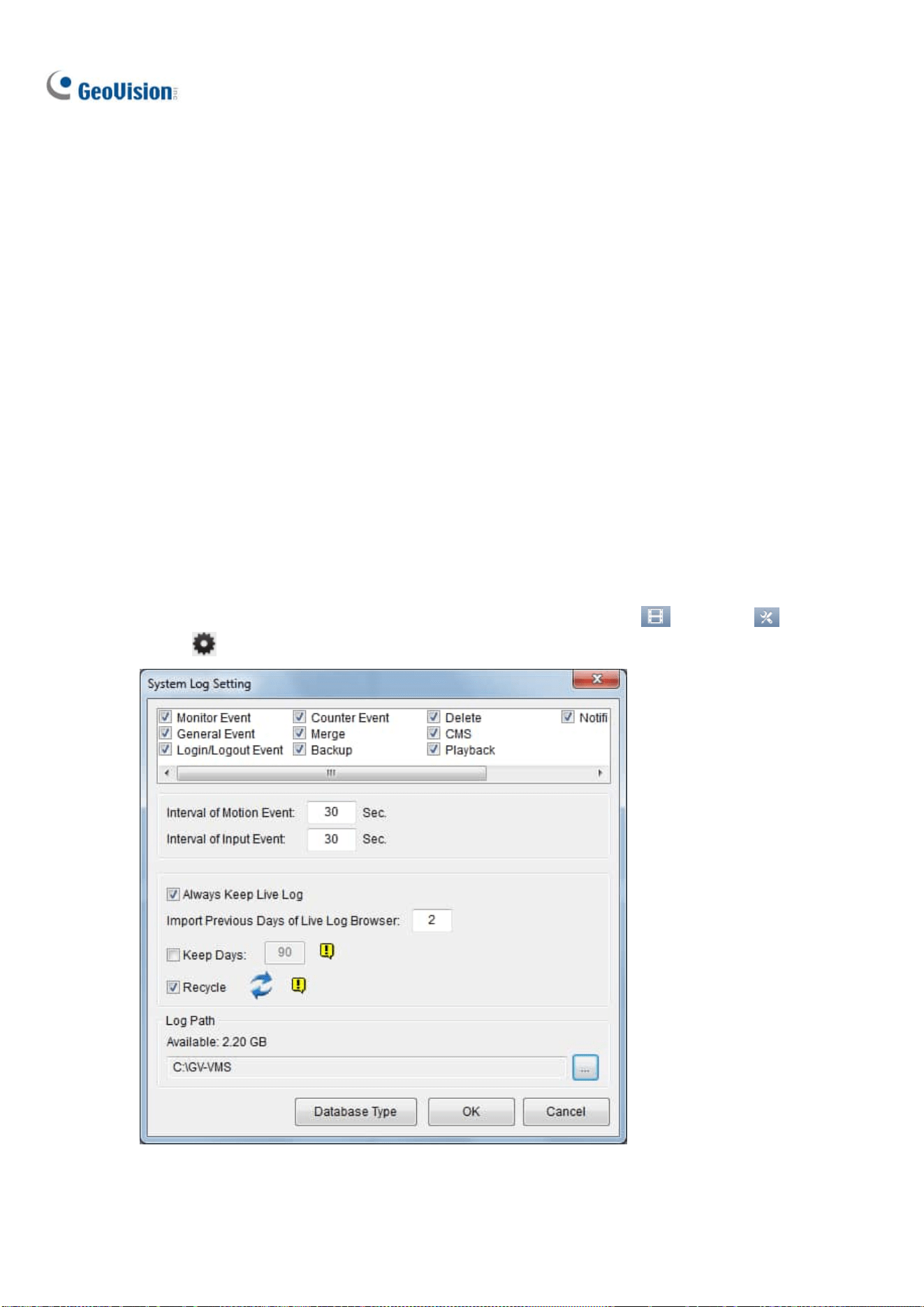
48
1.8.3 Exporting and Importing Schedule Settings
Schedule settings can be exported into an .xml file, and imported back later or to another GV-VMS.
1. In the Schedule dialog box, click Schedule and click Export or Import. A dialog box appears.
2. Specify the path to save the .xml file. Or, specify where the exported .xml file has been stored.
3. Click OK.
1.9 System Log
The System Log provides historical information that can help you track events, system problems and
object counting data.
1.9.1 Setting up System Log
In the System Log Setting, you can specify which events to record, the interval time to write the event
into the system, and the number of days to keep the logs for. Click ViewLog
> Toolbar >
Configure
> System Log Setting. This dialog box appears.
Figure 1-35

Configuring Main System
49
1
Select the types of event to register in the System Log:
Monitor Event: Registers motion-triggered and I/O-triggered events. For this feature to work, you
must enable the Register Motion Event option in Figure 1-10 or the Register Input Event option
in Figure 6-10.
General Event: Registers system startup/exit, network server start/stop, and monitoring
start/stop.
Login/Logout Event: Registers login/logout activities of local users to GV-VMS and WebCam
Server.
Counter Event: Registers counting results.
Merge: Registers the merging of recorded videos.
Backup: Registers the backup of recorded videos.
Delete: Registers the deletion of recorded videos through remote connection.
CMS: Registers the events of central monitoring services.
Playback: Registers playback of recorded videos.
Notification: Registers e-mail notifications.
The following settings are also available:
Interval of Motion Event: Specify the log interval between motion-triggered events, which
prevents the system to record events too frequently when motion triggers are intensive.
Interval of Input Event: Specify the log interval between input-triggered events, which prevents
the system to record events too frequently when input triggers are intensive.
Always Keep Live Log: Display the latest logs in the System Log tables (see Viewing System
Log later in this chapter). When not selected, the logs of the time selected in the ViewLog timeline
will be displayed if available.
Import Previous Days of Live Log Browser: Specify how many days of data to be loaded into
the System Log.
Keep Days: Set the number of days to keep the logs.
Recycle: Enable the system to delete old log files to make space for newer files when the space
of assigned Log Path is below 500 MB.
Log Path: Specify a storage path for the logs. By default, it is at :\GV folder\. The available free
space of the storage path will be displayed.
Database Type: Select Microsoft Office Access Database or M
icrosoft SQL Server as a
database, and fill out the required connection information.

50
1.9.2 Viewing System Log
To view the System Log, click ViewLog > Toolbar > Tools > System Log. The
following options are available: Monitor Table, CMS Table, and Advanced.
Monitor Table
Local events on GV-VMS are displayed.
Figure 1-36
[Monitor] Shows events related to camera connection and motion. Double-clicking an event will allow
you to view the related video (if available) in ViewLog.
[System] Shows system startup/exit, network server start/stop, and monitoring start/stop.
[Login] Shows whom and when has logged in and out of GV-VMS and WebCam server.
[Counter] Shows the information and results of GV-VMS’s counter functions.
[Merge] Shows the merging events of recorded videos.
[Backup] Shows the backup events of recorded videos.
[Delete] Shows the deletion of recorded videos through remote connection.
[Notification] Shows e-mail notifications.
[I/O] Shows the events related to I/O trigger.
[Playback] Shows the playback of recorded videos.
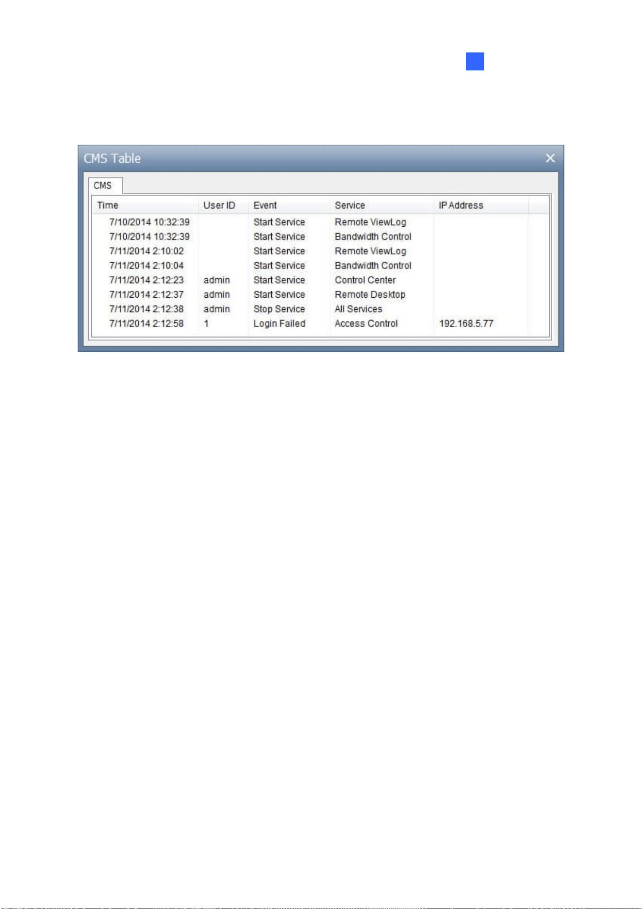
Configuring Main System
51
1
CMS Table
CMS Table shows the connection status, login activities and service start related to CMS.
Figure 1-37
Advanced Log Browser
See Advanced Log Browser in Chapter 4.

52
1.10 Other Functions
1.10.1 Popping up Live View
To pop up live view upon events, click Home > Toolbar > Configure > Camera Popup
Setting. This dialog box appears.
Figure 1-38
Dwell Time: Specify the amount of time a popup live video to remain in the foreground.
Interrupt Interval: Specify the interval between live video popups. This feature is useful when
several cameras are activated for a popup alert at the same time.
Camera Motion Invoke: Select the camera to enable auto popup upon motion detection.
Monitoring of the camera is required.
Input Invoke: Select an input module using the drop-down list and select the input number using
the arrow buttons. Select Input Invoke and assign a camera to the input device. Whenever the
input is triggered, the live video of the assigned camera will pop up. I/O monitoring is required.
Note: You can use the Mask Region function in the Advanced Motion Detection Setup dialog box
(Figure 1-10) to mask off certain areas of the camera image that you don’t want to detect motion.
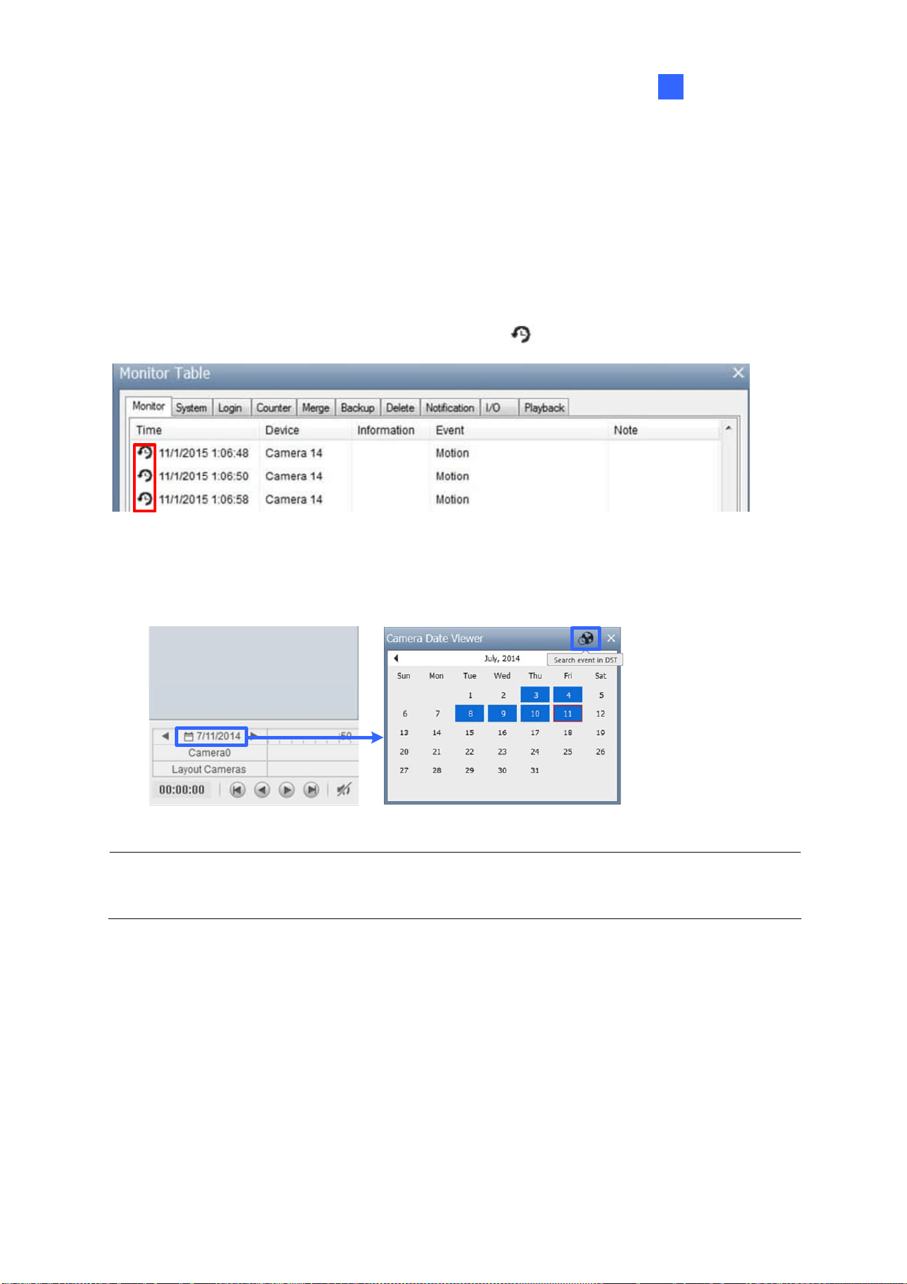
Configuring Main System
53
1
1.10.2 Adjusting to Daylight Saving Time
GV-VMS can automatically adjust to Daylight Saving Time (DST). If you are in a time zone that uses
DST, make sure DST is enabled. In Windows’ Control Panel, go to Date and Time, click Change Time
Zone, and make sure Automatically adjust clock for Daylight Saving Time is selected.
In the System Log, DST events are labeled with clock icons
in the Time column.
Figure 1-39
In ViewLog, click the Camera Date Viewer and click Search Event in DST.
Figure 1-40
Note: Videos recorded during DST periods start with “GvDST”, e.g. GvDST20140722.avi, to
differentiate from regular video files that start with “Event”, e.g. Event20081022.avi.
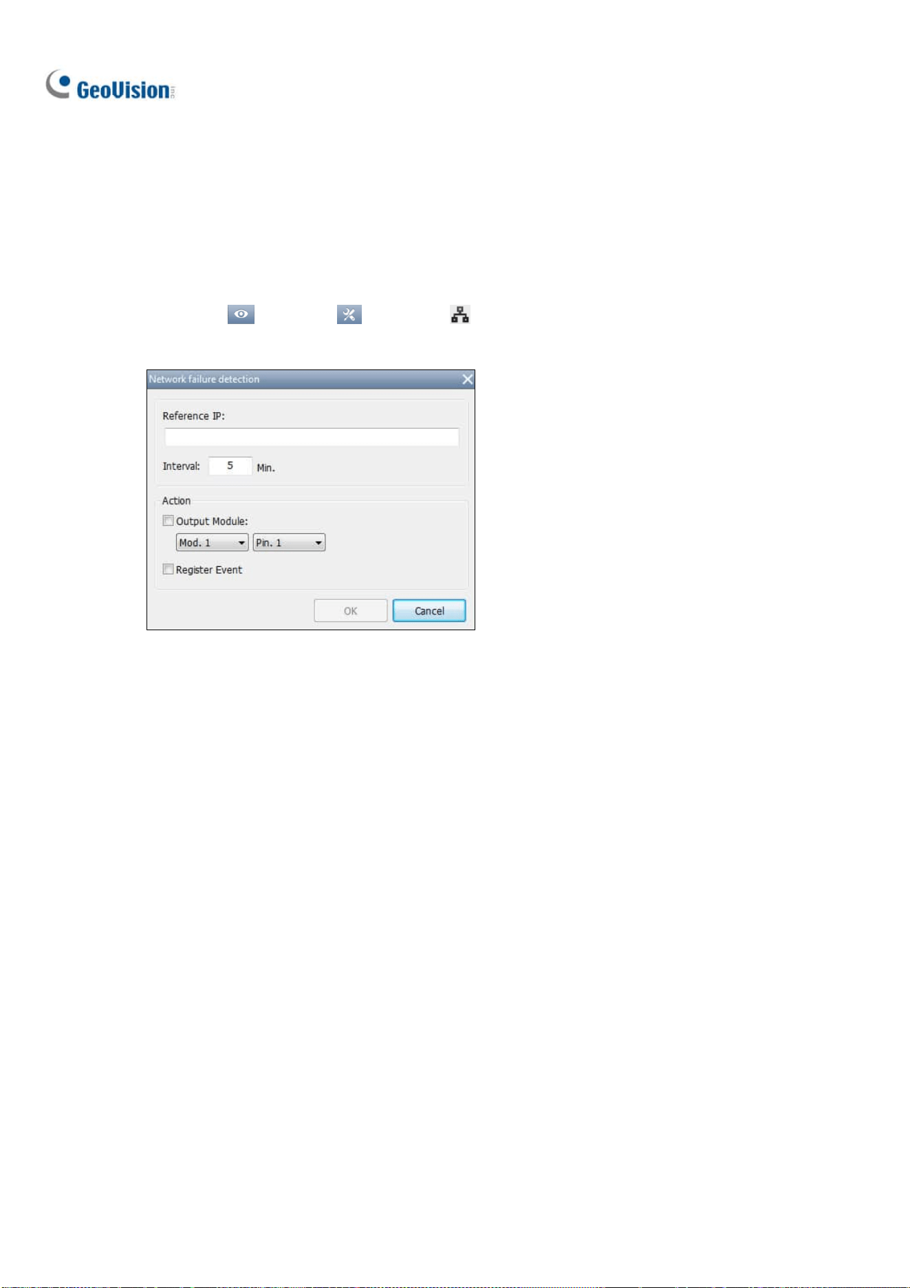
54
1.10.3 Setting up Network Failure Detection
The Network Failure Detection function triggers an output device when the network connection
between GV-VMS and the specified network host has failed.
1. Click Home
> Toolbar > Network > Network Failure Detection. This dialog box
appears.
Figure 1-41
2. Under IP Address, type the IP address or domain name of the remote host.
3. Next to Interval, type the time interval between each ping in minutes ranging from 1 to 999. If the
interval is 5 minutes, GV-VMS will ping the network host every 5 minutes to check if the
connection is still active.
4. Under Action, enable Output Module and select the output module and pin number.
5. Enable Register Event to record errors to the System Log.
6. Click OK.
The selected output device will be triggered when the network host does not respond to GV-VMS’s
ping message.

Configuring Main System
55
1
1.11 PTZ Camera
With the PTZ control panel, you can control PTZ functions, e.g. pan, tilt, zoom, focus and preset points.
1. Move the cursor to the camera live view of a connected PTZ camera and click Tools
.
Figure 1-42
2. Click PTZ Control to enable PTZ function.
3. You can control GV-IP Speed Domes using the following actions:
Double-Click: The camera will center on the spot you clicked.
Drag: You can select Random Move or Center Move after right-clicking the live view.
Random Move: Drag a line on the live view and the camera will move toward the
direction you dragged.
Center Move: Drag a box on the live view and the camera will zoom in on the area you
dragged.
Tip: Alternatively, you can disable the PTZ functions of a PTZ camera by right-clicking it on the IP
Device Setup page and selecting the Disable PTZ Operation option.

56
1.11.1 Accessing PTZ Control Panel and Auto Functions
After PTZ Control is enabled, move the cursor to the live view to see the PTZ control panel. Note that
the PTZ control panel is hidden when live view resolution is less than 240 x 180.
Note: From GV-VMS V16.10.3, ONVIF PTZ cameras no longer supports Iris Open / Close function
on the PTZ control panel.
Focus In / Out
Zoom In / Out
Home
Figure 1-43
In the PTZ control panel, click Home
to access the advanced PTZ functions below. The options
available may differ depending on the model of your PTZ camera.
Home: Returns the camera to Home position.
Iris Open / Close: Adjusts the camera iris. The iris Control buttons are only available for GV-IP
Speed Dome.
Auto Focus: Adjusts the camera focus according to the subject.
Auto Iris: Adjusts the iris opening according to amount of light in the environment.
Auto Go: Allows you to enable Cruise, AutoPan, Sequence and Tour functions. You can click
Stop Auto Go to stop the Auto function you have enabled.
Auto Set: Allows you to set up AutoPan and Cruise functions. See the section below for details.
Preset Go: Moves the PTZ to a preset point by clicking the preset number.
Preset Set: Allows you to configure up to 256 PTZ preset points. Move the camera to the position
where you want set a preset point and then select a preset point number here.

Configuring Main System
57
1
Auto Pan
The PTZ camera will continuously move between two horizontal positions. You can configure up to 8
sets of Auto Pan mode.
1. Move the camera to the start position of the AutoPan.
2. To mark the start position, click the Home button
in the PTZ Control Panel, select Auto Set,
and select Start AutoPan1.
3. Move the camera to the end position of the AutoPan. Any movement in the vertical direction will
not be included in the AutoPan.
4. To mark the end position, click the Home button
, select Auto Set, and select End AutoPan1.
5. To create another Auto Pan mode, repeat the steps above using a different Auto Pan number.
To enable the AutoPan, click the Home button
, select Auto Go, and select the AutoPan number
created. To stop the AutoPan, simply click a Pan/Tilt button in the PTZ Control Panel to interrupt the
AutoPan, or you can click the Home button
, select Auto Go, and select Stop Auto Go Function.
Cruise
You can set up a route consisting of different directions, angles, and zooms for the PTZ camera to
follow. Up to 4 Cruises can be created.
1. Move the camera to the start position of the Cruise.
2. To mark the start position, click the Home button
in the PTZ Control Panel, select Auto Set,
and select Set Cruise 1.
3. Move the camera according to how you want the camera to move during the Cruise. The camera
positions, zooms, and speed of the movement will all be recorded for the Cruise. .
4. When you are finished with setting up the Cruise, click the Home button
, select Auto Set,
and select Set Cruise Stop.
5. To set up another Cruise route, repeat the steps above and select a different Cruise number.
To enable the Cruise route, click the Home button
, select Auto Go, and select the Cruise number
created. To stop the Cruise route, simply click a Pan/Tilt button in the PTZ Control Panel to interrupt
the Cruise function, or you can click the Home button
, select Auto Go, and select Stop Auto Go
Function.

58
1.11.2 Setting up Idle Protection and Advanced Functions
In the Content List, right-click the PTZ camera and select PTZ Setup. This dialog box appears.
Figure 1-44
PT Speed: Adjusts the speed of pan and tilt movements.
Advanced: Click Setup to access advanced functions, such as image attributes, sequence, tour
and Home position. Consult the manual of the connected PTZ model for details.
[Idle Protection]
When the PTZ camera remains stationary for a certain period of time, the PTZ can automatically move
to a Preset Point, enable an Auto function, begin a Multi Position Tour or start the PTZ schedule.
1. Click Enable.
2. Set the Idle Time. The PTZ camera will follow the action selected in the next step after the idle
time exceeds the specified Idle Time.
3. Select Preset, Auto, Multi Position Tour or Schedule as protection mode. See Setting up Multi
Position Tour below.
4. Click OK.

Configuring Main System
59
1
Setting up Multi Position Tour
You can create a PTZ tour with up to 64 preset points. Note the number of preset points depends on
your PTZ capacity.
1. Select Multi Position Tour in the PTZ Configuration dialog box, and click the Setup button. This
dialog box appears.
Figure 1-45
2. Select a Preset as a starting point.
3. Set the Dwell Time that the PTZ will remain at each preset point.
4. Click Add and repeat Steps 2-3 to build more points in the tour.
1.12 QView
If there are multiple monitors connected, you can use the QView feature to display full-screen live view
of a camera on a separate monitor.
1. Click Home
> Toolbar > Configure > System Configure > Set Position. This
dialog box appears.
Figure 1-46

60
2. In the QView section, select a desired monitor from the Select Monitor drop-down list to open a
full-monitor display and click OK.
3. Double-click a camera view on the live view grid. The camera view is now displayed in full screen
on the designated monitor.
4. To switch another live view to a full-monitor display, simply double-click another camera view.
To record short video clips on a full-monitor display, see Creating a Storyline in QView later in this
chapter.
1.13 Storyline
With the Storyline feature, you can combine camera images from multiple channels into a sequence of
short video clips of a specific incident, such as gambling fraud, shoplifting and other fraudulent
activities. The recorded videos can be saved and played back later using a media player. This feature
is available in live view, video playback and QView display.
1.13.1 Creating a Storyline in Live View
First, drag the Zoom Window to a live view grid. Any camera views on the Zoom Window will be
recorded as a storyline.
1. Set up the screen division with the camera channels of interest.
2. In the Content List, select Layout, click Windows and drag Zoom Window to a live view grid.
3. To display a live view on the Zoom Window for recording, click the Zoom button
in the
top-right corner of a camera view.
4. On the Zoom Window, click the Tools icon
> Storyline to start recording. The orange label
indicates that the recording is in progress.
Figure 1-47

Configuring Main System
61
1
5. To record from another camera view, click the Zoom button of that camera view.
6. When you finish, deselect Storyline to stop recording. The Edit Description dialog box appears.
7. Type a name or description for the video clip and click OK.
Note:
1. The recording duration is limited to 30 minutes per storyline.
2. The resolution of storyline can be set to 1280 x 1024 (default) or 1920 x 1080. To change the
resolution, select Toolbar > Configure > System Configure > Record Setting and click the
down button next to Storyline.
Figure 1-48
1.13.2 Creating a Storyline in Video Playback
The procedures of creating a storyline with playback videos are si milar to those for the live view.
1. Click ViewLog
> Toolbar > Content List and drag Zoom Window onto a
playback grid.
2. To display a video on the Zoom Window, click the Zoom button
on the top right of a playback
video.
3. On the Zoom Window, click the Tools icon
> Storyline to start recording.
4. To record another video, click the Zoom button of that playback video.
1.13.3 Creating a Storyline in QView
1. Follow the instructions in QView earlier in this chapter to set up a full-monitor display.
2. On the designated monitor, click Tools
> Storyline to start recording.
3. To record the live video from another camera, simply double-click another camera view.

62
1.13.4 Accessing a Storyline
After creating the storyline, select ViewLog > Toolbar > Tools > Story Line. Your
storyline will be listed in the window below.
Figure 1-49
Right-click a storyline on the list to access more features, such as playback, changing the file path and
editing the description. You can also use the Filter button
to search for the desired storylines.
1.14 GV-VR360 Dewarped View
GV-VMS provides two dewarped modes for GV-VR360 under Content List (Home > Toolbar
> Content List ).
Figure 1-50

Configuring Main System
63
1
GV-VR360: The undewarped image of GV-VR360.
VR 360 V1: A dewarped mode of GV-VR360 that allows manual control to view all angles of the
image. Click and hold on the image to adjust the angle of view and click
to zoom in.
VR 360 V2: A dewarped mode of GV-VR360 that automatically pans around the image 360º
endlessly. Click
or to adjust the speed of the auto pan and click to zoom in.
Figure 1-51
Note:
1. To view the dewarped image of GV-VR360 on GV-VMS, the graphic card must support DirectX
10.1 or above.
2. Up to 2 GV-VR360 can be connected to a GV-VMS with a total frame rate of 24 fps.

64
Chapter 2
IP Camera Setup .................................. 65
2.1 Adding IP Cameras ............................................................................ 65
2.1.1 Adding Cameras Manually............................................................ 66
2.1.2 Scanning for Cameras .................................................................. 68
2.1.3 Mapping GV-IP Cameras using GV-IP Device Utility .................... 68
2.1.4 Adding Cameras of Mobile Devices using GV-Live Streaming..... 69
2.2 Configuring Individual IP Cameras ............................................... 69
2.2.1 Configuring Video Settings........................................................... 70
2.2.2 Configuring Audio Settings........................................................... 72
2.2.3 Configuring General Settings ....................................................... 73
2.3 Connection through RTSP, ONVIF & PSIA .................................. 74
2.4 On Demand Display............................................................................ 77

65
IP Camera Setup
2.1 Adding IP Cameras
There are several ways to connect IP devices to GV-VMS, and the procedures may vary depending on
the device. To access the IP Device Setup, click Home
> Toolbar > Configure >
Camera Install.
Figure 2-1
To manually set up an IP device, click Add Camera
.
To detect for IP devices on the LAN, click Scan Camera
.
To detect for and automatically add multiple IP devices on the LAN, click Automatic Setup
.
To import IP devices from GV-IP Device Utility, click Import Camera
.
To map IP devices through GV-IP Device Utility, click IP Device Utility
.
To license GV-VMS Pro and third-party cameras using software license, click GeoVision
License Activation Tool
, and see the technical notice for instructions.
For details on Automatic Setup, see Adding Cameras in Chapter 1. For other methods, see the
sections below.
CHAPTER
2

66
Third-Party IP Devices
Aside from GV-IP devices, GV-VMS also supports third-parity IP devices, through ONVIF, RTSP and/or
PSIA.
In the event of unbaling to detect a third-party device through Scan Camera or Automatic Setup, the
device can be added through Manual Setup. See Connection through RTSP, ONVIF & PSIA later in
this chapter.
2.1.1 Adding Cameras Manually
1. To manually add IP devices, click Add Camera in the IP Device Setup (Figure 2-1).
2. Type the IP address, username and password of the IP device. Modify the default HTTP port 80 if
necessary.
3. Select a camera brand and model name from the Brand and Device drop-down lists, respectively.
This dialog box appears.
Figure 2-2
4. Configure the options listed below, which may vary between camera brands.
Dual Streams: GV-IP Cameras are set to dual streams by default. Select this option to apply
the dual-streaming settings (lower resolution for live view and higher resolution for recording) if
the camera supports dual streams.
Query: Detect and apply the current codec and resolution setting on the camera. This function
may not be available for some third-party cameras.
Camera list: Select a camera number.

IP Camera Setup
67
2
Port: Modify the video streaming port of 10000 if necessary.
Stream Type: You may have the option of Single Stream or Dual Streams depending on
camera models.
Codec Type: You may have different codec options depending on camera models. If the
selected camera supports dual streaming, the live view codec and recording codec can be set
differently.
Resolution: You may select the different resolutions for live view and recording.
5. Click Apply to add the IP camera to the IP Device List.
6. To connect the added camera, select the checkbox beside the ID column. The Status icon turns
green upon successful connection, with the video resolution and bit rate being displayed in the
correspondent columns.
Figure 2-3
7. To change the number of the camera, click the device’s ID and select a desired number. Note this
function is only available for disconnected cameras.
Note: The indication of status icons is as below.
Connected
The camera is connected.
Connecting
GV-VMS is trying to connect to the camera.
Connection Failed
Unable to connect to the camera. Place the cursor on the red icon to
see the error message.
Inactive Camera
The camera is inactive. Select the checkbox to connect to the
camera.
Started Monitoring
The camera is under monitoring.
Pre-Rec Enabled
Pre-recording is enabled.
Tips: You can access the camera’s own configuration interface by right-clicking the IP camera and
selecting Remote Camera Setting.

68
2.1.2 Scanning for Cameras
1. To detect for IP devices on the LAN, click Scan Camera in the IP Device Setup (Figure 2-1).
The Scan Camera dialog box appears.
2. Click Start Scan. The IP devices detected are displayed.
3. Double-click the IP device you wish to connect to, type its username and password and click OK.
Figure 2-2 appears.
4. Click Apply. The IP camera is added to the IP Device List and automatically enabled for
connection.
2.1.3 Mapping GV-IP Cameras using GV-IP Device Utility
GV-IP Device Utility detects all available IP devices within the LAN and allows users to map detected
cameras to the specified channels. Users can then export the device list and import it into GV-VMS. In
addition, GV-IP Device Utility also lets users to quickly set IP addresses, upgrade firmware,
export/import device settings for and reboot IP devices.
Click IP Device Utility
in the IP Device Setup (Figure 2-1). All the available IP cameras on the
LAN are detected and listed in the window.
Figure 2-4
To map IP cameras to the channels of GV-VMS, see 7. Assigning Camera Channels for
GV-DVR / NVR / VMS in GV-IP Device Utility Guide
.
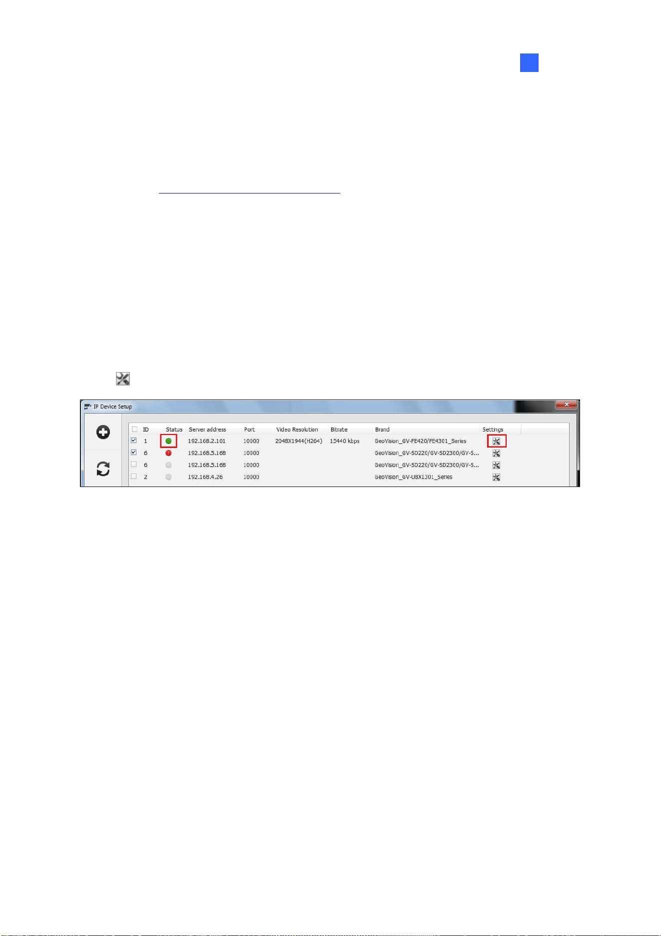
IP Camera Setup
69
2
2.1.4 Adding Cameras of Mobile Devices using GV-Live Streaming
Only supported by GV-VMS V17.4 or later, GV-Live Streaming is a paid mobile app that allows the
camera of your Android / iOS mobile device to connect and stream live view to GV-VMS via GV-Relay.
For details, see GV-Live Streaming Installation Guide
.
2.2 Configuring Individual IP Cameras
To configure the IP camera settings such as video, audio and other general settings, click the Setup
button
of the connected camera on the IP Device List.
Figure 2-5

70
2.2.1 Configuring Video Settings
You can configure video settings such as frame rate, codec type and resolution of the camera.
Figure 2-6
[Stream Setting] Select a stream from the drop-down list. Settings for Main Stream will be used for
recording. Live view can use either Main Stream or Sub Stream depending on the On Demand settings.
For details, see On Demand Display later in this chapter.
Codec Selection: Set the codec to MJPEG, H.264, or H.265.
FPS: Set the number of frames per second.
GOP: Set the number of seconds between each key frame. For example, when the FPS is set to
30, a GOP of 0.5 means there will be 1 key frame among every 15 frames.
Quality and Bitrate: When using the H.264 / H.265 codec, you can select between VBR and
CBR.
VBR (Variable Bitrate): The quality of the video stream is kept as constant as possible at the
cost of a varying bitrate. Set the image quality to one of the 5 standards: Standard, Fair,
Good, Great and Excellent. Set a Max. Bitrate if needed, or select Auto if you do not want to
enable this function.

IP Camera Setup
71
2
CBR (Constant Bitrate): CBR is used to achieve a set bitrate by varying the quality of the
H.264 / H.265 stream. Select one of the bitrates from the drop-down list.
Smart Streaming:
Static Scene: Set the image quality to one of the 5 standards: Standard, Fair, Good, Great
and Excellent. Set a Max. Bitrate if needed.
Dynamic Scene: Set the image quality to one of the 5 standards: Standard, Fair, Good,
Great and Excellent. Set a Max. Bitrate if needed.
Bitrate Reduction Level: The bigger the value the more bitrates can be reduced in static
scenes, thus saving the recording size.
Resolution Change the display ratio and resolution.
[Video Lost / Connection Lost]
Trigger Output: Trigger the specified output module upon video lost or connection lost until the
output device is manually turned off. To configure the output device, see I/O Device Setup in
Chapter 6.
Right-Arrow button: Set the counting time between 0 and 1000 seconds to delay the
activation of the specified output module.
[Camera Lens] Select Wide Angle if you want to correct warping toward the edge of the camera
image. For details, see Wide Angle Lens Dewarping in Chapter 3.
If you are using third-party fisheye cameras, select IMV1 Panorama for cameras installed with an
ImmerVision IMV1 Panorama Lens, and select Fisheye for other third-party fisheye cameras. For
details, see Setting up a Third-Party Fisheye Camera in Chapter 3.
[Video Attribute] Adjust video characteristics, such as brightness, contrast, saturation, sharpness and
gamma.
[Image Orientation] Adjust the image orientation by selecting Normal, Horizontal Mirror, Vertical
Flip, Rotate 180, Rotate 90 an
d Rotate 270 (Corridor format).
Note:
1. Changes made to the Video Setting page will c
hange the settings on the IP camera.
2. The Image Orientation options for Rotate 90 and Rotate 270 (Corridor format) are only
available for GV-IP Cameras that support the function.

72
2.2.2 Configuring Audio Settings
On the Audio Setting page, you can adjust audio devices and listen to live sound.
Figure 2-7
Audio Gain: Increase or decrease the gain of the microphone.
Wave Out: Select to listen to the audio around the camera.
Denoise: Select to reduce audio noise.
Rec Audio: Select Rec Audio to record the audio around the camera.
By sensitivity: Audio recording is activated when the volume reaches the sensitivity level
indicated.
Round-the-Clock Audio: Audio recording is continuously enabled.
Audio Format: Select an audio format from the drop-down list. The default is 16 KHz, 16 bit.

IP Camera Setup
73
2
2.2.3 Configuring General Settings
You can configure the general settings, such as for video recording.
Figure 2-8
Network Time Out: When network disconnection exceeds the specified time period, the status
icon on the IP Device List (Figure 2-1) becomes yellow.
Live View Decode Postpone Time: Specify the number of milliseconds to postpone live view
decoding. When the network connection with the IP device is unstable or when the time length
between frames is not evenly distributed, postponing the live view decoding will make the video
smoother. Note this function is only available for configuration when the camera is disconnected.
Frames to Keep in Live View Buffer: Specify the number of frames to keep in the live view buffer.
When CPU performance is insufficient, you can reduce the number of frames kept in buffer to
achieve a real-time appearance by dropping frames. This setting does not affect the frame rate of
the recorded videos.
On Demand Display: Enable automatic adjustment of live view resolution. For details, see On
Demand Display later in this chapter.
Recording Codec Format: Specify whether to record in standard or GeoVision codec.
Automatically Adjust DST: When enabled, the time on the GV-IP Device Web interface will be
synchronized with the time of GV-VMS when DST period starts or ends on GV-VMS.
74
Video Lost / Connection Lost (Invoke Alarm): Enable if you want to trigger an alarm sound
upon connection lost. Click the Arrow button to select a sound.
Video Lost / Connection Lost (Notification): Enable if you want to send an e-mail notification
upon connection lost. See Setting up E-mail Notifications in Chapter 1 to set up the e-mail server.
Message Box Setting: When enabled, the Network Congestion message will pop up under such
a condition.
Live View Decode Frame Control (Main / Sub Stream): Set the live view frame rate for main
stream and sub stream.
When using MJPEG, every frame is a key frame, so the options of Max. frame and Key only
are grayed out.
When using H.264 / H.265, only one key frame is transmitted per the specified number of
frames, so you can select Key only to decode key frames only and omit all intermediate
frames or Max. frame to include all frames.
Recording Frame Rate Control: Set the recording frame rate for Urgent Event and General
Event. This function allows you to set different recording frame rates for motion, non-motion and
other alarm events. See Setting up Recording Settings for Individual Cameras in Chapter 1.
When using MJPEG, every frame is a key frame, so the options of Max. frame and Key only
are grayed out. You can specify the recording frame rate for Urgent Event and General
Event respectively.
When using H.264 / H.265, only one key frame is transmitted per the specified number of
frames. You can select Max. frame for Urgent event and select Key only for General event.
Set Codec and Resolution Automatically: If enabled, GV-VMS will resume the configured
codec and resolution when it detects the changes made by the camera.
POE Switch Reboots IP Camera: Restart a specified camera via its connected GV-POE Switch
with the functionality of Web management. Type the ID and PW of the switch to start rebooting.
2.3 Connection through RTSP, ONVIF & PSIA
To add IP devices compliant with RTSP, ONVIF or PSIA to GV-VMS, follow the steps below.
1. To add through the abovementioned protocols, click Home
> Toolbar > Configure
> Camera Install.

IP Camera Setup
75
2
2. Click Add Camera
to manually add an IP camera. This dialog box appears.
3. Type the IP address, username and password of the IP camera. Modify the default HTTP port if
necessary.
4. Select Protocol from the Brand drop-down list.
5. Select the protocol that is supported by your IP camera from the Device drop-down list.
Figure 2-9
GV_HTTP_SDK: For SDK users only. The RTSP protocol uses a HTTP port for data
streaming from the IP camera.
GV_HTTP_SDK_RTSP: For SDK users only. The RTSP protocol uses a HTTP port for data
streaming from the IP camera.
ONVIF: This option is for connecting the camera using ONVIF standards.
PSIA: This option is for connecting the camera using PSIA standards.
RTSP over HTTP: The RTSP protocol uses a HTTP port for data streaming from the IP
camera.
RTSP over TCP: The RTSP protocol uses a TCP port for data streaming from the IP camera.
RTSP over UDP: The RTSP protocol uses an UDP port for data streaming from the IP
camera.

76
6. If you select ONVIF, this dialog box appears after the system confirms that the camera is ONVIF
compatible. Click Dual Stream to enable the second stream if needed, and click the Setting
button
next to Stream1 and Stream 2 to adjust the following information.
Figure 2-10
Codec: Select H.264 or JPEG.
Resolution: Set a resolution.
Quality: Adjust the image quality. The range of image quality varies for different brands.
Frame Rate: Set a maximum frame rate. The range of frame rate varies for different brands.
Bitrate: The current bit rate setting of the IP device will be displayed. You can adjust the bit
rate limit within the device’s supported bit rate range if needed.
GOV: Set the number of frames between each key frame. For example, a GOV of 10 means
there will be 1 key frame every 10 frames.
7. If you select PSIA, a dialog box appears after the system confirms that the camera is PSIA
compatible. Click Apply.
8. If you select RTSP, select Dual Streams to enable the Sub Stream if needed and type the RTSP
link address.
For the RTSP command, consult the documentation of your IP camera. For instance:
For an AXIS IP camera, type RTSP://<IP of the IP camera>/<codec>/media.amp
For a HIKVISION IP camera, type RTSP://username:password@<IP of the IP Camera>
9. Click OK to add the IP camera to the IP Device List.

IP Camera Setup
77
2
2.4 On Demand Display
For cameras that support dual streaming with different resolutions, you can select the On Demand
Display option to enable automatic adjustment of live view resolution. This option produces good
image quality without causing high CPU usage.
You will need to set a value of X times the resolution of the sub stream as the threshold. When the
camera image on the screen is bigger than the threshold, the system will switch to the higher
resolution streaming, usually the main stream. Such adjustment is enabled when using the view
modes that require higher quality images, such as single view or PIP / PAP mode. The system will
switch to the lower resolution streaming to reduce CPU usage when watching live view in view modes
where higher resolution does not make a difference, such as highly divided divisions.
1. Make sure the IP camera has been added to GV-VMS and you have selected Dual Stream during
setup. For details, see Adding IP Cameras earlier in this chapter.
2. In the IP Device Setup (Figure 2-1), click the Setup button
of the desired connected camera
within the IP Device List and select General Setting.
3. In the On Demand Display field, click Enable and select a value. When the camera image on the
screen is X times bigger than the resolution of sub stream, the system will switch to the higher
resolution streaming.
Figure 2-11
Note:
1. The On Demand Display function is not supported for Privacy Mask.
2. The On Demand Display function is not supported by GV-Fisheye cameras

78
Application Example
The resolution of sub stream is 640 x 480, and a value of 1.2 times the resolution of the sub stream
has been selected for the On Demand Display function.
Higher Resolution Streaming
Figure 2-12
The camera image in the middle has a resolution of 1152 x 540, so the higher resolution streaming
will be used, because 1152 x 540 is bigger than 1.2 x 640 x 480.
Lower Resolution Streaming
640 x 360 < 1.2 x 640 x 480,
lower resolution streaming will be used
Figure 2-13
After switching to 9-channel screen division, the resolution for each channel is 640 x 360, which is
smaller than 1.2 x 640 x 480, so the lower resolution streaming will be used.

79
Chapter 3
Video Analysis ..............................................81
3.1 Object Counting and Intrusion Alarm .......................................... 81
3.1.1 Object Counting.............................................................................................. 81
3.1.2 Intrusion Alarm...............................................................................................84
3.2 Object Index......................................................................................... 87
3.2.1 Setting up Object Index...............................................................................87
3.2.2 Viewing Object Index ...................................................................................89
3.2.3 Searching Object Index ............................................................................... 90
3.3 Automatic Video Snapshots ........................................................... 91
3.3.1 Setting up Video Snapshots.......................................................................91
3.3.2 Searching Video Snapshots .......................................................................92
3.4 Face Detection.................................................................................... 93
3.4.1 Setting up Face Detection ..........................................................................93
3.4.2 Searching Face Detection Snapshots .................................................... 94
3.5 Face Count ........................................................................................... 95
3.5.1 Installing the Camera................................................................................... 95
3.5.2 Setting up Face Count..................................................................................96
3.6 Face Recognition................................................................................ 99
3.6.1 Enrolling Face Data....................................................................................... 99
3.6.2 Synchronizing Face Database .................................................................101
3.6.3 Starting Face Recognition ........................................................................102
3.6.4 Viewing and Searching for Face Recognition Events .....................102
3.6.5 Defining Access Schedule ........................................................................104
3.6.6 Configuring Recognition Alerts and Recognition Database .........108
3.6.7 Tracking Recognized Faces .....................................................................109
3.7 Privacy Mask Protection ................................................................ 112
3.7.1 Setting up a Privacy Mask ........................................................................ 112
3.7.2 Granting Access Privileges to Recoverable Areas .......................... 113
3.8 Panorama View................................................................................. 114
3.8.1 The Main Window......................................................................................... 114
3.8.2 Stitching a Panorama View with Overlapping Areas ...................... 115

80
3.8.3 Easy Mode with No Overlapping Area .................................................. 117
3.8.4 Accessing a Panorama View ................................................................... 119
3.9 Video Defogging................................................................................ 120
3.10 Video Stabilization ........................................................................ 121
3.11 Wide Angle Lens Dewarping....................................................... 122
3.12 Crowd Detection ............................................................................ 124
3.13 Advanced Scene Change Detection ........................................ 126
3.14 Advanced Unattended Object Detection................................ 128
3.15 Advanced Missing Object Detection........................................ 131
3.16 Text Overlay .................................................................................... 133
3.17 Fisheye View ................................................................................... 134
3.17.1 Setting up Fisheye View .........................................................................135
3.17.2 Setting up a Third-Party Fisheye Camera.........................................137
3.17.3 Object Tracking..........................................................................................139
3.18 Video Analysis by Camera .......................................................... 143
3.19 Heat Map........................................................................................... 146
3.19.1 Enabling Heat Map....................................................................................146
3.19.2 Accessing the Heat Map in Recordings.............................................148
3.20 Event Alert through E-mail Notifications................................ 149
3.21 PTZ Object Tracking ..................................................................... 150
3.21.1 Dual-Camera Tracking .............................................................................150
3.21.2 Single Camera Tracking..........................................................................153
3.22 Panoramic PTZ Object Tracking ............................................... 155
3.22.1 Accessing the Live View.........................................................................156
3.22.2 Automatic Object Tracking ....................................................................156
3.23 Specifications ................................................................................. 160

81
Video Analysis
3.1 Object Counting and Intrusion Alarm
Object Counting provides bi-directional counting of objects under the surveillance area. It can count
any moving objects (such as vehicles), people or animals. Intrusion alarm can be set to send
notifications when an object moves into the defined region.
Note: It is not recommended to apply the counter function to Fisheye cameras.
3.1.1 Object Counting
You can select up to 16 cameras to set up Object Counting.
1. Click Home
> Toolbar > Configure > Video process. The Setup dialog box
appears.
2. From the Video Analysis drop-down list, select Counter/Intrusion Alarm Setting, select the
desired cameras and click Setting. This page appears.
Figure 3-1
CHAPTER
3

82
3. Select a desired camera under Choose Camera and select Enable Setting to define the counter.
Define Detection Zones: Select this option to define the detection zones.
a. On the live view, draw at least two boxes to mark the in and out detection zones.
Each detection zone is numbered. Use these buttons to edit the detection zones:
Name Button Function
Reverse
Flips the detection zone.
Switch
Switches to another detection zone.
Delete
Deletes the detection zone.
Direction
Configures the in and out directions. See Step 3-b.
b. Click the
button to define the in and out criteria. This dialog box appears.
Figure 3-2
c. Select In/Out under Set Direction and define the direction in Select Detection Zone.
d. Click Add. The setting is added and appears in the table below.
e. Click OK. The directions are added and indicated by arrows on the live view.
Define Object Size: Select this option and click
to pause the live view.
Outline a size matching that of targeted objects on the live view. Click
to resume.
4. To test your counting settings, select Live from the Test Count drop-down list and click the Test
button to start testing. The number in Counting Result should change as objects move through
the detection zone. Optionally use the Sensitivity slider to adjust detection sensitivity as needed.
5. Click OK to apply the settings.
6. Start monitoring to begin counting. The counted objects, people or animals are indicated on the
live view with yellow boxes.

Video Analysis
83
3
More options in the Counter dialog box:
Show Alarm Regions: Displays the detection zones on the preview image.
Skip Frame: Skips frames to lower the CPU loading, where the system only counts objects
every three frames. This option may reduce the accuracy of counting result.
Reset Alert: Specify a time interval, between 1 and 1440 minutes, to reset the recorded
counting result in the System Log.
Note:
1. Draw the detection zones as closely as possible to avoid omission of counting when target
objects show up in the unmarked area and move only through one of the two boundaries.
Figure 3-3
2. To include counting results in the recorded files, see Setting up Text Overlay later in this
chapter.
3. To view the logs for counter events, click View Log, Toolbar, Tools, System Log, Monitor
Table and click the Counter tab.
4. Optionally create a schedule for counter to be enabled only at the time periods specified. For
details, see Creating Schedules in Chapter 1.

84
3.1.2 Intrusion Alarm
Up to 16 cameras can be set up for Intrusion Alarm.
1. To set Intrusion Alarm for object(s) entering a defined region Click Home
> Toolbar
>
Configure
> Video process. The Setup dialog box appears.
2. Select Counter/Intrusion Alarm Setting in Video Analysis, select the desired camera, click
Setting and click the Alarm tab. This dialog box appears.
Figure 3-4
3. Select a desired camera under Choose Camera and select Enable Setting to define the
intrusion alarm.
Define Detection Zones: Select this option to define the detection zones.
a. On the live view, draw at least two boxes to mark the in and out detection zones.
Each detection zone is numbered. Use these buttons to edit the detection zones:
Name Button Function
Reverse
Flips the detection zone.
Switch
Switches to another detection zone.
Delete
Deletes the detection zone.
Direction
Configures the in and out directions. See Step 3-b.

Video Analysis
85
3
b. Click the
button to define the alarm criteria. This dialog box appears.
Figure 3-5
c. Select 1 Direction or 2 Direction under Set Direction and define the direction in Select
Detection Zone.
d. Click Add. The setting is added and appears in the table below.
e. Click OK. The directions are indicated by arrows on the live view.
Define Object Size: Select this option and click
to pause the live view.
Outline a size matching that of targeted objects on the live view. Click
to resume.
Define Image Depth: When the object moves toward or away from the camera along a path,
for example, a hallway, it appears larger when it is closer to the camera and vice versa.
Rather than using a fixed object size, you can define a maximum and minimum object size
according to the object’s proximity to the camera.
Figure 3-6
a. Select Define Image Depth and select With Image Depth using the drop-down list. A
line
appears.

86
b. Drag and place the line along the path where the objects will be moving. The larger icon
indicates the point closer to the camera.
c. Select Define Object Size. Click the larger icon
and click to pause the live
view. Use the mouse to outline the maximum size of objects on the live view.
d. Click the smaller icon
and repeat the step above to define the minimum size of
objects when they are further from the camera.
4. In the Setting section, there are two kinds of alarm modes:
Alarm Mode 1: The alarm sets off when the target object moves through the first detection
zone and touches the second detection zone in the defined direction.
Alarm Mode 2: The alarm sets off when the target object moves through the first detection
zone and its center moves through the second detection zone in the defined direction.
5. To set up alarm devices, configure any or both of the following options.
Invoke Alarm: Enable the computer alarm when an object enters the defined region. Click
the button next to the option to assign a .wav sound file.
Output Module: Enable an installed output device when an object enters the defined region.
Assign the output module and pin number.
6. To test your alarm settings, select Live from the Test Count drop-down list and click Test. When
intrusion objects are detected, the configured computer alarm or output device will be activated.
Optionally adjust the Sensitivity slider as needed.
7. Click OK to apply the setting.
8. Enable monitoring to start intrusion detection. The detected intruding objects are indicated on the
live view with red boxes.
When an intrusion event occurs, the configured computer alarm or output device will be activated, and
the event will be recorded as Intruder in the System Log for later retrieval
More options in the Alarm dialog box:
Show Alarm Regions and Skip Frame: See the same options in Object Counting above.
Never Recycle: Alarm-triggered events will never be recycled if selected.

Video Analysis
87
3
Note:
1. Draw the detection zones as closely as possible to avoid omission of intrusion events when
target objects show up in the unmarked area and only move through one of the two boundaries.
Figure 3-7
2. To view the logs for intrusion events, click View Log, Toolbar, Tools, System Log, Monitor
Table and click the Monitor tab.
3. Optionally create a schedule for intrusion alarm to be enabled only at the time periods specified.
See Creating Schedules in Chapter 1.
3.2 Object Index
The Object Index feature allows you to view the very first frame of a continuous movement in a video
stream. With Object Index Live Viewer, you may view the most recent 50 frames captured. When
accessing Object Index in ViewLog, you can easily locate and play back events by selecting and
specifying the desired camera channels and time periods.
3.2.1 Setting up Object Index
You can select up to 16 cameras for which their Object Index is kept.
1. Click Home
> Toolbar > Configure > Video process. The Setup dialog box
appears.

88
2. From the Video Analysis drop-down list, select Object Index, select the desired cameras and click
Setting. This dialog box appears.
Figure 3-8
4. Select one camera from the drop-down list and configure the following.
Mask Region: Use the mouse to outline a mask area where motion will be ignored.
Set Location: Click the button to assign a path to save the log files and image snapshots.
Keep Days: Specify the number of days the log files will be kept for, from 1 to 999 days.
Recycle: Select to recycle the oldest log files when the remaining disk space is less than 500
MB. When both Keep Days and Recycle are selected, the system reacts to whichever
condition that is first met.
Never Recycle: Log files and image snapshots will not be recycled when selected.
Noise Tolerance: Use the slider to adjust the tolerance level. The higher the level, the more
tolerant the system is to video noise.
5. Click OK to apply the settings.
6. Enable monitoring to start the function.
Note: Optionally create a schedule for object index to be enabled only at the time periods specified.
For details, see Creating Schedules in Chapter 1.

Video Analysis
89
3
3.2.2 Viewing Object Index
Once set, you can start to view the most recent frames captured, up to 50 frames, through Object
Index.
1. Start camera monitoring. The detected face or objects are indicated on the live view.
2. Click Home
> Toolbar > Tools > Live Object Index. The Live Viewer window
appears and displays the most recent 50 frames recorded.
3. Click the lock icon and select Lock to pause the real-time updating of Object Index.
Figure 3-9
4. With the camera name and recorded time shown below each frame image, double-click an image
to play back its recording. The recording will be displayed in ViewLog, where you can play it back
using the Timeline.
Note: To display the corresponding recording, make sure the layout in ViewLog includes the camera
channel selected.

90
3.2.3 Searching Object Index
In ViewLog, you can locate, and instantly play back, the frames of the desired cameras within a
specified time.
1. Click ViewLog
> Toolbar > Tools > Object Index.
2. Select the desired camera channels at the top and click Refresh to display all the event frames of
the channels selected, including the ones most recently recorded.
Figure 3-10
3. Select the desired date and time to display the event frames during that time period.
4. Double-click the frame you want to play back. The recording will be displayed in ViewLog, where
you can play back using the Timeline.
Note: To display the corresponding recording, make sure the layout in ViewLog includes the camera
channel selected.
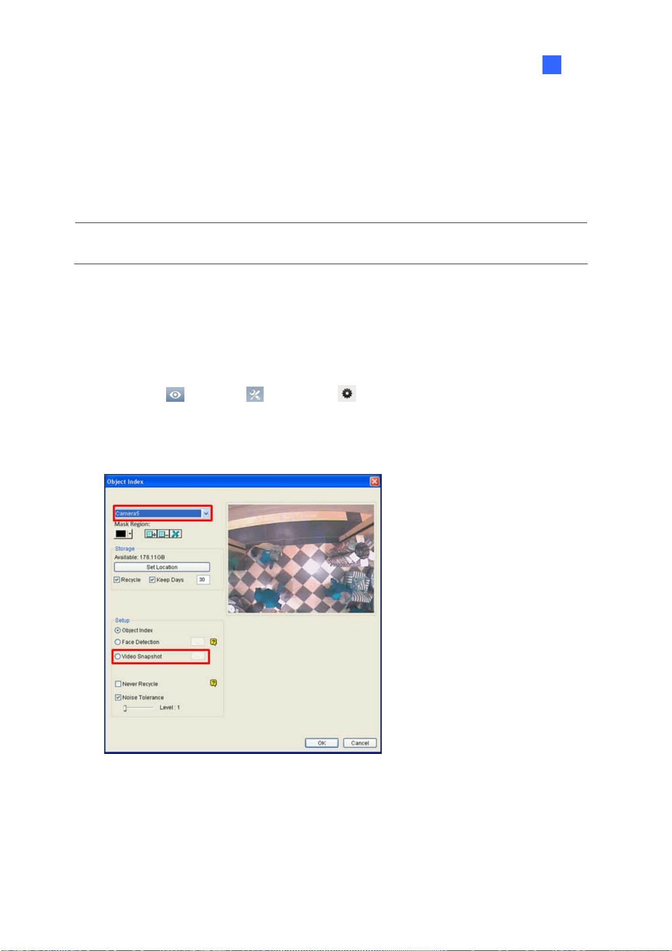
Video Analysis
91
3
3.3 Automatic Video Snapshots
The Video Snapshot allows the system to take up to 30 snapshots per second as monitoring starts.
This function allows you to keep the surveillance records as still JPEG images instead of AVI videos
when storage space is limited.
Note: After you start monitoring, the system will start taking video snapshots whether there is motion
or not.
3.3.1 Setting up Video Snapshots
You can select up to 16 cameras to take video snapshots.
1. Click Home
> Toolbar > Configure > Video process. The Setup dialog box
appears.
2. From the Video Analysis drop-down list, select Object Index, select the desired cameras and click
Setting. The Object Index dialog box appears.
Figure 3-11
3. Select one camera from the drop-down list.
A. Optionally configure the Storage settings. See Step 4, Setting up Object Index earlier in this
Chapter.
B. Select Video Snapshot.
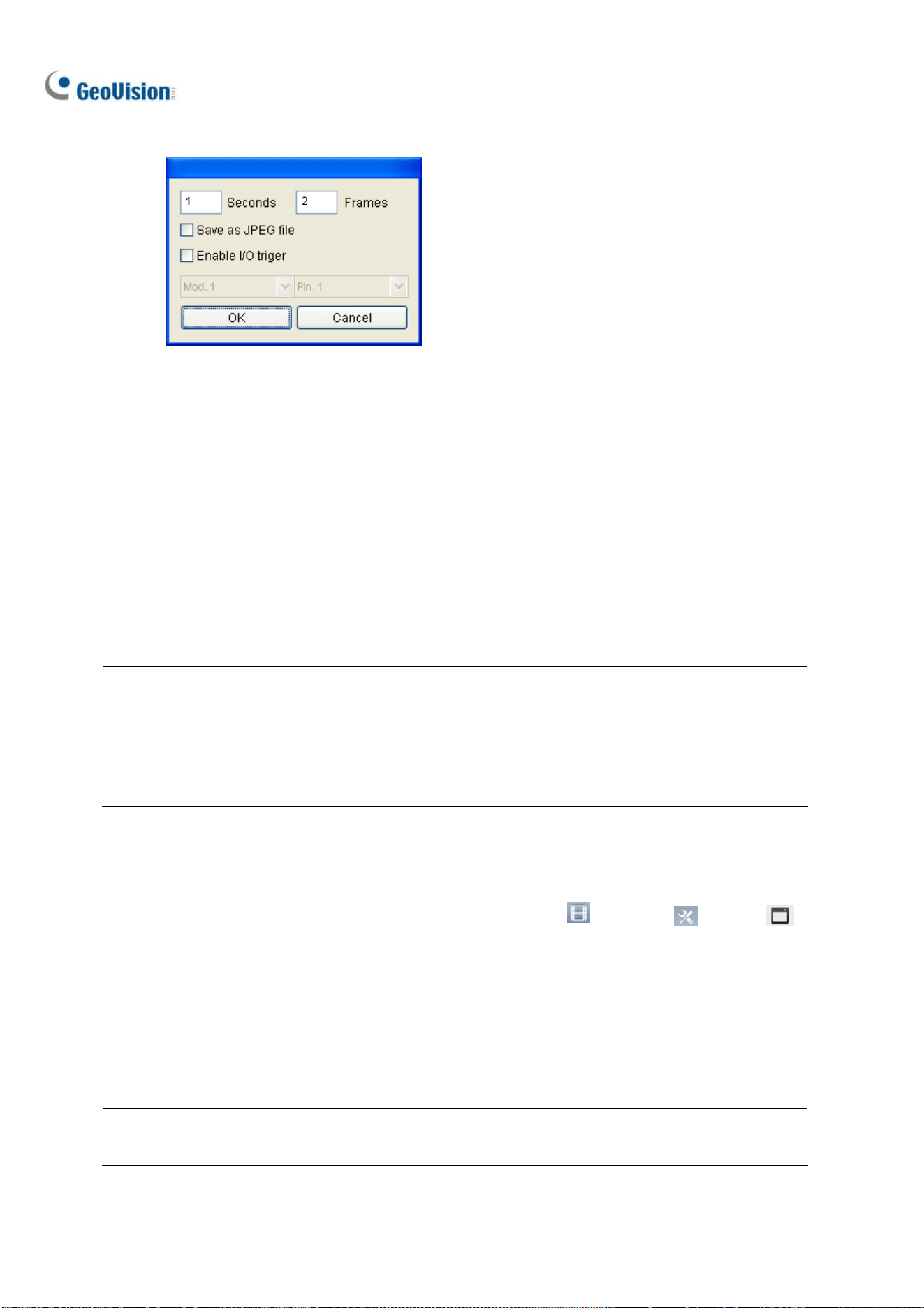
92
C. Click […] after Video Snapshot for further setup.
Figure 3-12
4. Specifies the frequency of automatic video snapshot. By default, the system will take 2 frames
every second when the monitoring starts.
Save as JPEG file: Saves the images in JPEG format. Otherwise, you can only access the
snapshots using the ViewLog player.
Enable I/O Trigger: Takes snapshots only when the assigned input device is triggered.
5. To configure another camera, select a different camera on Step 3.
6. Click OK to apply the settings.
7. Start monitoring to take snapshots.
Note:
1. For details on other settings of the Object Index dialog box, see Step 4, Setting up Object Index
earlier in this chapter.
2. Optionally create a schedule for video snapshot function to be enabled only at the time periods
specified. For details, see Creating Schedules in Chapter 1.
3.3.2 Searching Video Snapshots
1. To locate video snapshots of desired cameras, click ViewLog > Toolbar > Tools >
Object Index. A window similar to that of Object Index appears (Figure 3-10).
2. Select a desired camera channel and click Refresh to display all its event frames, including the
ones most recently recorded.
3. Select the desired date and time to display all the video snapshots captured, along with their event
frames, during that time period.
Note: When Save as JPEG file is enabled (Figure 3-12), you can also view the video snapshots
from the directory specified by Set Location (Figure 3-11).

Video Analysis
93
3
3.4 Face Detection
The Face Detection enables the system to detect and record human faces, including individual faces
when a group of people enter the scene. This feature captures human faces only, ignoring other body
parts, objects or background views.
3.4.1 Setting up Face Detection
Up to 16 cameras can be configured for this application.
1. Click Home
> Toolbar > Configure > Video process. The Setup dialog box
appears.
2. From the Video Analysis drop-down list, select Object Index, select the desired cameras, and
then click Setting. The Object Index dialog box appears.
Figure 3-13
3. Select one camera from the drop-down list.
A. Optionally configure the Mask Region, Storage and Noise Tolerance settings. For details, see
Step 4, Setting up Object Index earlier in this chapter.
B. Select Face Detection.
C. Click […] after Face Detection to adjust the sensitivity. The higher the value, the more sensitive
face detection is.
4. To configure another camera, select a different camera on Step 3
5. Click OK.

94
6. Start monitoring.
Note:
1. For details on other settings of the Object Index dialog box, see Step 4, Setting up Object Index
earlier in this chapter.
2. Optionally create a schedule for face detection to be enabled only at the time periods specified.
For details, see Creating Schedules in Chapter 1.
3.4.2 Searching Face Detection Snapshots
1. Click Home > Toolbar > Tools > Live Object Index to display the Live Viewer
window.
Figure 3-14
2. Double-click a desired frame to instantly play back its recorded file.
Note: Consider the following when installing the camera for face detection:
Face contour must be clearly seen
Only faces tilting within the range of 15 vertically and 30 ~ 45 horizontally can be detected.
The face to be detected must cover least 1/10 of the screen.

Video Analysis
95
3
3.5 Face Count
The Face Count function allows you to count the number of faces that appear in the image. You can
also select to invoke a computer alarm or trigger an output device when a face is detected or when no
face is detected.
The number of faces counted is saved to GV-Web Report which can analyze counting data from
multiple GV-VMS systems. For details, see GV-Web Report User’s Manual.
3.5.1 Installing the Camera
1. Install the camera inside an entrance pointing outward. The Face Count function is designed to
detect front-view faces only, and the area of the detected face must take up 10% to 50% of the
live image.
Figure 3-15
2. Avoid installing the camera where it is subjected to direct sunlight or reflections. The lighting of
the entrance where you set the camera should be sufficient but not too bright or dark. Light
should be distributed evenly across faces without too much light coming from one side. Sharp
shadow edges in the camera view may affect the accuracy of face count.
Note:
1. Up to 16 cameras can be configured for this function.
2. The Face Count results are only available on GV-Web Report V2.2.6.0 or later.

96
3.5.2 Setting up Face Count
1. Click Home > Toolbar > Configure > Video process. The Setup dialog box
appears.
2. From the Video Analysis drop-down list, select Face Count, select the desired cameras and click
Setting. This dialog box appears.
Figure 3-16
3. Under Camera Selection, select a camera from the drop-down list to be configured.
4. The following configurations are available:
[Definition]
Mask Region: Use the mouse to outline a mask area where motion will be ignored.
Detected Face Size: You can adjust the Minimum Face Size and the Maximum Face
Size to instruct the system to only detect faces within that size range. Pause the live
image by clicking
before configuring.
[Setting]
Detection Type
Face Count: Counts the number of faces. The counting results are only available
on GV-Web Report. To connect to GV-Web Report, see the Saves counting
results to GV-Web Report option below.
Face Detected Alert: Detects faces to invoke a computer alarm or triggers an
output device.

Video Analysis
97
3
No Face Detected Alert: Invokes a computer alarm or triggers an output device
when no face is detected after the number of seconds specified in the Detection
Interval.
Reset at: Type a counting reset time between 0 and 23. For example, if you type 23, the
number of faces counted will become zero at 23 o’clock daily.
Sensitivity: Adjust the detection sensitivity by moving the slider. The higher the value the
more sensitive the system is to motion. The default value is 3.
Detection Interval:
When Face Detected Alert and Enable Upon Input Trigger are both selected, the
Detection Interval slider specifies the number of seconds you want the system to
detect faces when the input device is triggered.
When No Face Detected Alert is selected, the system will attempt to detect the
faces for the duration specified for Detection Interval.
[Option]
Enable upon input trigger: The system will begin detecting only when the input device
is triggered. Assign an input module and pin number for the device.
Saves counting results to GV-Web Report: Saves the face counting results to
GV-Web Report. Type the Domain Name or IP Address, Port, User Name, and
Password of GV-Web Report. After settings, click the Test button to see if the
connection succeeds.
Invoke Alarm: Activates the computer sound alarm when faces are detected under Face
Detected Alert or when no face is detected under No Face Detected Alert. Click the […]
button to designate a sound file for the computer alarm.
Output Module: Activates the output device when faces are detected under Face
Detected Alert or when no face is detected under No Face Detected Alert. Assign an
output module and pin number for the device.
Never Recycle: Prevents recorded events from being recycled when the recycle
threshold is reached.
5. Click the Test button to see if the settings have been configured according to your preference. If
you have set a detection interval, the test will only run for the number of seconds you specified.
6. Click OK to apply the settings.
7. Start monitoring to run the application. The detected (counted) faces are indicated on the live view
with green boxes.

98
Note:
1. Events triggered under Face Detected Alert or No Face Detected Alert will be recorded to the
System Log for later retrieval. In the System Log, the events are recorded as Face Count under
the Monitor tab (ViewLog > Toolbar > Tools > System Log).
2. The Face Count results will only be saved when Saves counting results to GV-Web Report is
selected and GV-Web Report is connected.
3. The counter function is not recommended to be applied in fisheye cameras.
4. Optionally create a schedule for face count to be enabled only at the time periods specified. For
details, see Creating Schedules in Chapter 1.

Video Analysis
99
3
3.6 Face Recognition
Face Recognition integrates the facial recognition abilities of GV-Face Recognition Camera for the
system to distinguish detected human faces. Based on the camera’s Face Database, this feature
displays the names of the recognized persons on the live view, while recording the recognition events
during video recording. Additionally, the recognition events recorded can at the same time be used to
trigger e-mail alerts and/or output and computer alarms based on the rules defined.
3.6.1 Enrolling Face Data
Prior to using Face Recognition, it is required to create the necessary recognition data via Face
Enrollment — adding photos of the persons to be recognized into the Face Database of GV-Face
Recognition Camera.
Enroll faces by adding portrait photos directly into the camra’s database, see the steps
below.
Synchronize face data from other connected camera, see Synchronizing Face Database
later in this section.
IMPORTANT:
1. GV-VMS directly accesses and manages the Face Database of GV-Face Recognition Camera,
thus all changes made are done directly to the camera’s database.
2. Photos used as recognition data can be pictures of the persons previously taken or snapshots of
the persons captured by connected cameras.
3. All photos used for Face Enroll must meet the criteria as specified in No. 3 under Face
Recognition FAQ of the FAQ
.
1. Click Home
> Toolbar > Configure > Video process. The Setup dialog box
appears.
2. From the Video Analysis drop-down list, select IPCVA, select the desired cameras and click
Setting.
Note: GV-Face Recognition Cameras include GV-VD8700 and GV-FD8700-FR and this feature only
supported by GV-VMS V17.1 or later.

100
3. Select the desired channel from the drop-down list at the top, select Face Recognition >
>
Face Enroll.
Figure 3-17
4. Click Add to define a new Face ID. Alternatively, select or Search for an existing ID from the
Enrolled Face list.
Figure 3-18
5. Click Add, on the bottom the right side, to add photos and/or snapshots for the Face ID selected
from your local PC. Optionally crop the image added by selecting it and click Crop Image.
6. You can also configure the following options for the Face ID selected:
Name: Type a desired name for the Face ID.
Group: Select from a list of ten groups in which the Face ID shall be categorized under.
Click the
button to modify the group name. This setting can be used to trigger e-mail
alerts and/or output alarms when persons from a specified Group is recognized at the
surveillance site. See Configuring Face Setting later in this chapter.
Organization: Type a desired organization name for the Face ID.

Video Analysis
101
3
Access Schedule: Select a predefined schedule in which the Face ID is allowed access or
select Current Setting and click
to define an exclusive schedule for the person. To set
a schedule, refer to Defining Access Schedule later in this chapter for details.
7. Click OK to save.
Note: All changes made here take immediate effect on the Face Database of the selected camera.
3.6.2 Synchronizing Face Database
To synchronize the face databases of two or more cameras, follow Steps 1 to 3 in Enrolling Face Data
earlier in this chapter and select Face Database Synchronization. The following window appears.
Figure 3-19
Select Source Camera: Select the camera you want to synchronize from.
Select Sync Camera: Select the cameras that you want to be synchronized.
Sync Data: Click to start synchronizing.

102
3.6.3 Starting Face Recognition
Monitoring of the camera must be enabled for Face Recognition to work.
1. Make sure Face Recognition is enabled. Refer to Steps 1 to 3 in Enrolling Face Data earlier in
this chapter.
Figure 3-20
2. Start monitoring of the camera channel (Home
> Toolbar > Monitor > select
Channel).
3.6.4 Viewing and Searching for Face Recognition Events
When Face Recognition is enabled, all recognition events, along with recognition snapshots,
recognition time, and schedule alerts, when applicable, are recorded in an event log during video
recording. To view Face Recognition in recorded videos, click ViewLog
> Toolbar
>
Tools
> Face Recognition. This window appears.
Figure 3-21

Video Analysis
103
3
Show All: Select Show All, Show Identified Persons Only or Show Unknown Persons
Only to filter the recognition events displayed.
Event Image: Display the captured Snapshot of the recognition event. Double-click the
Snapshot to see the recording of the recognition event in ViewLog.
Name: Display the Name of the individual recognized. Written as “Unknown” if
unrecognizable.
Group: Display the Group the recognized person is categorized under in the Face Database.
Camera Name: Display the Channel in which the recognition event was recorded.
Time: Display the Time of the recognition event.
Alert: Record Schedule Alerts when the recognition event recorded is outside of the person’s
(Face ID) allowed access schedule.
Query: Click to access the Query window, where you can filter and search for recognition
events in selected camera channels.
Figure 3-22
Note: The Name search in Query functions as a keyword search and is case-sensitive.

104
3.6.5 Defining Access Schedule
Access Schedules are used to specify the time periods in which specific persons (Face ID) are allowed
or denied access of from Monday to Sunday. Whenever a person is recognized outside of his/her
allowed schedule, a schedule alert is recorded, which can be used to trigger e-mail alerts and/or
output alarms.
The Access schedule can be set in five steps:
Step 1 Setting up 24-hour Schedules
Define the minutes and hours a person is allowed / denied access of in a day.
Step 2 Setting up Weekly Schedules
Define the days a person is allowed / denied access of in a week.
Step 3 Assigning Access Schedules
Assign the defined schedules to the desired persons in Face Enrollment.
Step 4 Setting up Schedule Alerts to Trigger E-mails / Alarms
Select Schedule Alerts as the parameter to trigger e-mail alerts and output alarms in Face
Setting. See Configuring Face Setting later in this chapter.
Step 5 Starting Camera Monitoring
Start monitoring of the camera channels and enable Face Recognition to activate access
monitoring as defined by the Access Schedules.

Video Analysis
105
3
3.6.5.1 Step 1: Setting up 24-hour Schedules
Before creating weekly schedules, you need to first define a number of desired 24-hour schedules that
can be used to prepare the weekly schedules. Follow Steps 1 to 3 in Enrolling Face Data earlier in this
chapter and select Time. In this window, up to 254 24-hour schedules can be defined, with two default
schedules for “Full Access” and “Deny Access.”
Figure 3-23
1. Click the Add button
. An ID number ascending from the lowest existing ID will be
automatically generated. Type a desired name for the new schedule, e.g. Day Shift and click OK.
2. Click the Add Access Time button
. Then drag the mouse on the timeline to specify the time
periods of allowed access, e.g. from 09:00 to 19:00.
3. Repeat Steps 1 to 3 to create multiple schedules if needed, e.g. for Night Shift from 00:00 to
09:00 and 19:00 to 24:00 and for Supervisor from 07:00 to 24:00.
4. To remove time periods of allowed access, click the Delete Access Time button
. Then drag
the mouse over the periods that you want to remove.
5. Click OK to save the changes.
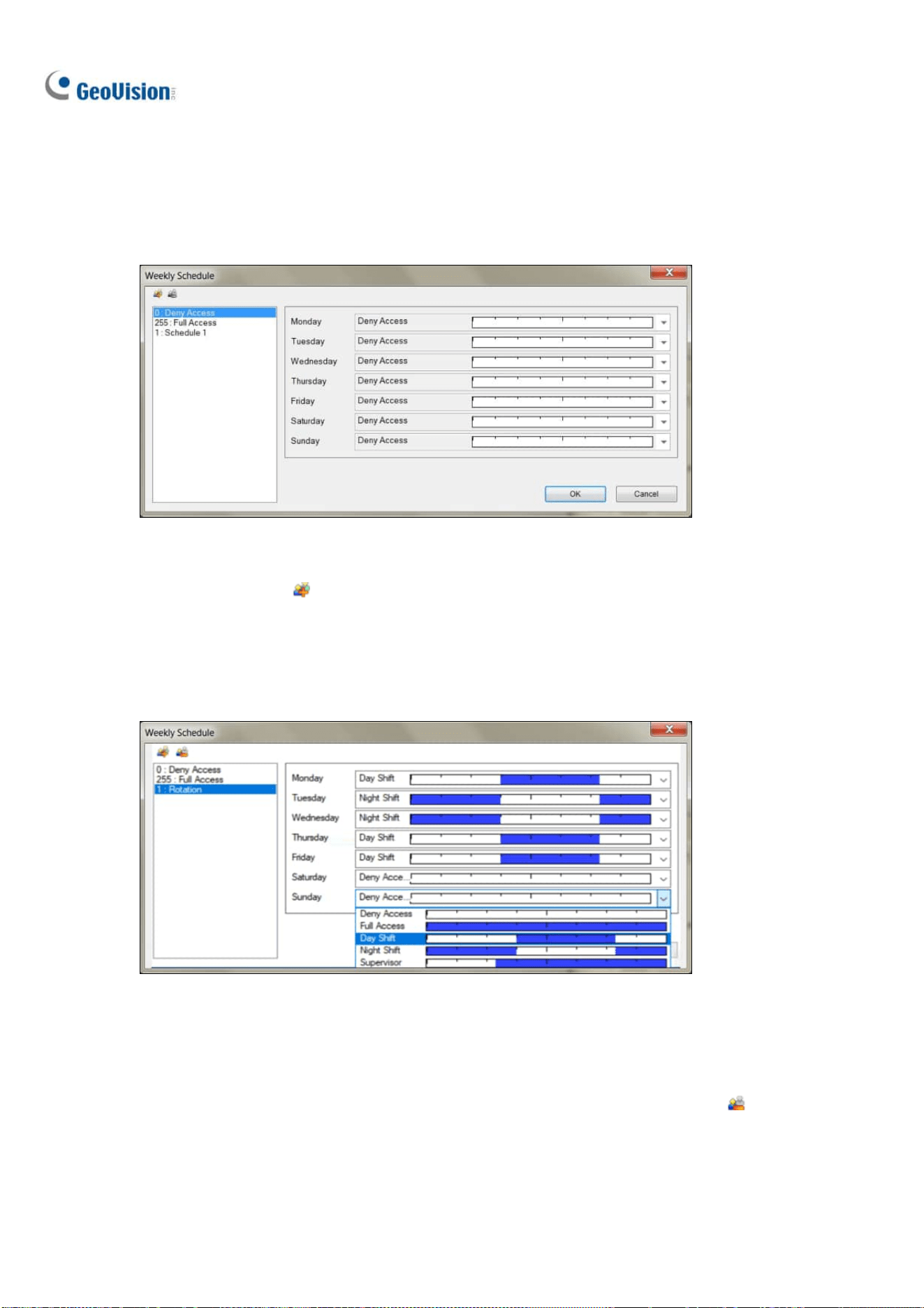
106
3.6.5.2 Step 2: Setting up Weekly Schedules
Once the desired 24-hour schedules are set, follow Steps 1 to 3 in Enrolling Face Data earlier in this
chapter and select Schedule. In this window, up to 254 weekly schedules can be defined, with two
default schedules for “Full Access” and “Deny Access.”
Figure 3-24
1. Click the Add button
. An ID number ascending from the lowest existing ID will be
automatically generated. Type a desired name for the new schedule, e.g. Rotation and click OK.
2. Select the desired schedules for Monday to Sunday, predefined from Step 1 earlier in this section,
in each of the respective drop-down lists, as exemplified below.
Figure 3-25
3. Repeat Steps 1 to 3 to create multiple schedules if needed, e.g. for Daytime-only and
Weekend-only access.
4. To delete schedules, select the schedule to be deleted and click the Remove button
.
5. Click OK to save the changes.

Video Analysis
107
3
3.6.5.3 Step 3: Assigning Access Schedules
Once the weekly schedules are set, follow Steps 1 to 4 in Enrolling Face Data earlier in this chapter,
select or Search for a desired Face ID and select a schedule in the Access Schedule drop-down list.
Figure 3-26
Once the Access Schedules are assigned, turn on monitoring of the camera channel and enable Face
Recognition, see Recording Recognition Events later in this chapter, to start access monitoring based
on the schedules.

108
3.6.6 Configuring Recognition Alerts and Recognition
Database
In this section, you can use Schedule Alerts, Unknown Alerts or the Recognition Events of a specified
Group, e.g. blacklist, to send e-mail notifications and/or trigger output alarms, and also configure the
database of face recognition events, including storage path of the snapshots and log files of
recognition events.
Note: For Face Setting to work, make sure Face Recognition is enabled, see Starting Face
Recognition later in this chapter.
To configure Face Setting, follow Steps 1 to 3 in Enrolling Face Data earlier in this chapter and select
Face Setting. This window appears.
Figure 3-27
Event Trigger: Select Schedule Alert or the Group of Face ID that e-mail notifications, or I/O
should be triggered for. For details on using Schedule Alerts, refer to Defining Access
Schedule earlier in this chapter. A GV-I/O Box needs to be connected to GV-VMS for the I/O
function to work.
For E-Mail, Set the minimum time Interval allowed, from 0 to 3600 seconds, in between
each e-mail notification.
For I/O, select the desired Output Module and Pin number.
Database Setting: Click to configure the Database Settings as below:

Video Analysis
109
3
Figure 3-28
Database Folder: Click the Browse button
to modify the save path for the snapshots
and log files of recorded Recognition Events.
Recycle: Enable to recycle the data in the Database Folder.
Keep Days: Type the desired number of days that data in the Database Folder should be
kept for, from 1 to 999.
Note: Make sure the e-mail and I/O functions are configured properly before use. For details, see
Setting up E-mail Notifications and Setting up I/O Devices in Chapter 1 and 6, respectively
.
3.6.7 Tracking Recognized Faces
Tracking of recognized faces can be displayed on the E-Map when there are multiple cameras with
synchronized Face Databases.
To display Face Tracking, refer to the following for the related settings:
Step 1 Synchronizing Face Database
To synchronize Face Databases, see Synchronizing Face Database earlier in this chapter.
Step 2 Creating E-Map(s)
To create E-Map(s) and add the camera, see Creating an E-Map in Chapter 8.
Step 3 Enabling Face Recognition
To enable Face Recognition, see Starting Face Recognition earlier in this chapter.
Step 4 Turning on Monitoring

110
Once all the related settings are set, turn on monitoring and you will see arrows indicating the
movements of recognized persons on the E-Map.
Figure 3-29
No. Name Description
1 Face Tracking Display the direction of movement of the individual recognized.
2 Latest Recognition Site The end point of the Face Tracking arrow indicates the
surveillance site (camera channel) where the recognized
individual was last seen.
3 Previous Recognition Site The initial point of the Face Tracking arrow indicates the
surveillance site (camera channel) where the recognized
individual was previously seen.
4 Recognition Event Display a live image of the Recognition Event.

Video Analysis
111
3
Adjusting the Display Mode on E-Map
To adjust the display mode of the recognition events on E-Map(s), click Tools and select Face
Recognition for the following options:
Figure 3-30
Show face and path: Selected by default, display both Face Tracking and the Recognition
Events on the E-Map.
Show face only: Display only the Recognition Events on the E-Map.
Hide face: Do not display any Recognition Events and Face Tracking on the E-Map.
Configuring Face Tracking
For an increased accuracy, you can modify the interval setting of Face Tracking based on your
surveillance needs.
1. In Content List of Live view, click Configure
> General Setting. This window appears.
Figure 3-31
2. Under Tracking Time, select the days (0~31), hours (0~23), minutes (0~59) and seconds (0~59)
to define the time interval in which Face Tracking is effective for. Face Tracking will not be
displayed for any subsequent Recognition Events occurring beyond the set Tracking Time.
3. Click OK to save the changes.

112
3.7 Privacy Mask Protection
The Privacy Mask can block out sensitive areas from view, covering the areas with black boxes in both
live view and recorded clips. This feature is ideal for locations with displays, keyboard sequences (e.g.
passwords), and for anywhere else you don’t want sensitive information visible.
You can also choose to retrieve the block-out areas during playback. The retrievable areas will be
protected by password.
3.7.1 Setting up a Privacy Mask
1. Click Home > Toolbar > Configure > Video process. The Setup dialog box
appears.
2. From the Video Analysis drop-down list, select Privacy Mask Setup, select the desired cameras,
and then click Setting. This dialog box appears.
Figure 3-32
3. Select a camera from the drop-down list.
4. Select Un-recoverable and/or Recoverable.
Un-recoverable: The block-out area(s) will not be retrievable in the recorded clips.
Recoverable: The block-out area(s) will be retrievable with password protection.
Note: No motion will be detected in the areas set up with Privacy Mask. To have Privacy Mask and
motion detection functions together, you need to use built-in motion detection function of the camera
instead (Home > Toolbar > Configure > Video Process > IPCVA > Setting > Motion Detection), as well
as enabling motion detection on the camera.

Video Analysis
113
3
5. Drag on the area(s) where you want to block out on the image. You will be prompted to click Add
to save the setting. The Un-recoverable region is marked in black, while the recoverable region is
shown in red.
6. Click OK to apply the settings.
3.7.2 Granting Access Privileges to Recoverable Areas
By default, only a Supervisor account is granted access to see the block-out areas on recorded videos.
To grant access rights to Power Users and Users, follow the steps below.
1. Click the login user button
on the main screen, select Password Setup > Local
Account Edit. The Local Account Edit dialog box appears.
2. Select one account, click the Privacy Mask tab, select Restore Recoverable Video and select
the camera to grant the privilege.
Figure 3-33
Note: If you open the event files (*.avi) directly from local disks, the valid ID and password are also
required to access the block-out areas. For details on retrieving the block-out areas in the exported
files, see Merging and Exporting Video in Chapter 4.
Note: Optionally create a schedule for Privacy Mask to be enabled only at the time periods specified.
For details, see Creating Schedules in Chapter 1.

114
3.8 Panorama View
A panorama view joins multiple camera images together and allows you to monitor a large area in one
view. The cameras selected for the panorama view will keep the recording in original format. Up to 4
sets of panorama views can be created. There are two ways to create a panorama view:
Stitch camera images together by overlapping and matching reference points
Use the Easy Mode to place camera images next to each other with no overlapping
In Content List of Live view, select Panorama > Configure
. The Panorama View Setup dialog
box appears.
3.8.1 The Main Window
Figure 3-34

Video Analysis
115
3
The controls on the Panorama View Setup dialog box:
No. Name Description
1 Add Adds an image for automatic splicing.
2 Undo Cancels the settings.
3 Manual Setting Manually splices the images together.
4 Blending Makes the spliced images seamless.
5 Demo Displays the setup procedure.
6 Left / Right Place the selected image to the left or right of the previous image.
7 Top / Bottom Place the selected image on the top or bottom of the previous image.
8 Save Before Exit Saves the created panorama view and closes the dialog box.
9 Exit Closes the dialog box.
10 Preview Window Displays the selected source image or the spliced images.
11 Easy Mode Places camera views next to each other with no overlaps.
12 Panorama Selection
Selects the panorama set for the images to be spliced together.
Clicks again to rename the panorama set.
13 Source Selects the source image to be spliced.
14 Selected Source Displays the selected image.
3.8.2 Stitching a Panorama View with Overlapping Areas
To stitch images from different cameras together, follow these steps:
1. Select one panorama set (No. 12, Figure 3-34) from the drop-down list. If you want to rename the
selected panorama set, type the name in the field.
2. Select one camera from the Source drop-down list and click Add. The image will be the reference
image on which other images will be sliced.

116
3. Select another camera from the Source drop-down list (No. 13, Figure 3-34) and click Manual
Setting (No.3, Figure 3-34). This dialog box appears.
Figure 3-35
4. From the Source drop-down list, select one camera as the Source image to be stitched with the
Reference image.
5. To stitch the two images together, click on a significant point in the Reference image and then look
for the same point in the Source image. A dialog box of point selection will prompt you to confirm.
You need to set up 3 points for stitching.
Note: For the best result, position the points in the overlapping areas on both images. Avoid placing
the points in a cluster or lining them up straight.
6. The resulting image is displayed in the Preview window. If satisfied with the result, click OK to exit
the setup dialog box. If not, re-enter the 3 points for stitching.
7. If you want to stitch a third image or more, click Manual Setting and repeat Steps 3 to 5 multiple
times.
8. When you finish stitching images, click the Save Before Exit button (No.6, Figure 3-34) to save
the created panorama view before exiting the Panorama View Setup dialog box.
Note: The resolution of the images to be stitched will be reduced to 320 x 240. A panorama view
has a resolution limit of 1920 x 1080. Once the limit is reached, you cannot stitch more images to
the created panorama view.

Video Analysis
117
3
9. This panorama view is saved to the Panorama category in the Content List.
Figure 3-36
10. Drag the created panorama view to the live view grid for display.
3.8.3 Easy Mode with No Overlapping Area
When you have multiple camera views covering areas right next to each other with no overlaps, the
Easy Mode allows you to simply place camera views together.
Figure 3-37
1. Select Easy Mode (Video source must be of the same resolution) (No. 11, Figure 3-34).

118
2. Use the Source drop-down list (No. 13, Figure 3-34) to select the first camera view to be placed
in the panorama and click the Add
button. The first camera view is added to the Preview
Window.
Figure 3-38
3. To add a second camera view, select the camera from the Source drop-down list.
4. To place the camera view on the left or right of the first camera view, click the
icon and
select to place the second view on the Left or Right of the first view.
Figure 3-39

Video Analysis
119
3
5. To place the camera view above or below the first camera view, click the
icon and select to
place the second view on the Top or Bottom of the first view.
6. Repeat the steps for any additional cameras.
Note: You will only be able to add additional cameras next to the last camera view added. For
example, when adding a third camera, you can only use the direction buttons
in relation to
the second camera. You will not be able to go back and select the first camera.
7. When you finish stitching images, click the Save Before Exit button
before exiting.
8. This panorama view is saved to the Panorama category in the Content List (Figure 3-36).
9. Drag the created panorama view to the live view grid for display.
3.8.4 Accessing a Panorama View
Drag the configured panorama from the Content List (Figure 3-36) to the live view. The panorama view
is displayed on the main screen.
Figure 3-40
Right-click the panorama view to have these options:
Snapshot: Save the current panorama view as an image file.
Zoom: Put the cursor on the live view and scroll your mouse to zoom the live view.

120
3.9 Video Defogging
Smoky environments and bad weather, such as rain, snow or fog, all affect image quality and reduce
scene visibility. This feature helps to enhance image quality for live viewing.
Note:
1. This function takes high CPU and memory usage. Make sure at least 1 GB of RAM is installed on
your system.
2. Defogging is not supported when Heat Map is enabled.
1. Click Home
> Toolbar > Configure > Video process. The Setup dialog box
appears.
2. From the Video Analysis drop-down list, select Defog, select the desired cameras, and click
Setting. This dialog box appears.
Figure 3-41
3. Use the drop-down list to select a camera.
4. When the image enhancement is enabled, the system load will increase. Adjust the Refresh rate
by moving the slider bar to optimize system performance.
5. If you want to view the demonstration of this function, click the Demo button.
Note:
1. This function only applies to live view and does not affect the recorded video. To apply defogging
to recorded videos during playback, on ViewLog
,
right-click the desired image > Effects >

Video Analysis
121
3
Defog.
2. For better image quality, it is recommended to change the streaming to single stream before you
enable the video analysis effect. This effect does not support On Demand Display for automatic
adjustment of live video resolution in single-channel division.
1. Optionally create a schedule for video defogging to be enabled only at the time periods specified.
For details, see Creating Schedules in Chapter 1.
3.10 Video Stabilization
Images from a shaky camera are jittery or blurry. This feature helps to reduce camera shake, leaving
you with clear and steady images.
Note:
1. This function takes high CPU and memory usage. Make sure at least 1 GB of RAM is installed on
your system
2. Stabilization is not supported when Heat Map is enabled.
1. Click Home
> Toolbar > Configure > Video process. The Setup dialog box
appears.
2. From the Video Analysis drop-down list, select Stabilizer, select the desired cameras, and click
Setting. This dialog box appears.
Figure 3-42
3. Use the drop-down list to select one camera. The enhanced view is shown on the right.
4. When the image enhancement is enabled, the system load will increase. Adjust the Refresh rate
by moving the slider to optimize system performance.

122
5. If you want to view the demonstration of this function, click the Demo button.
Note:
3. This function only applies to live view and does not affect the recorded video. To apply
stabilization to recorded videos during playback, on ViewLog, right-click the desired image >
Effects > Stabilizer.
4. For better image quality, it is recommended to change the streaming to single stream before you
enable video stabilization. This effect does not support On Demand Display for automatic
adjustment of live video resolution in single-channel division.
5. Optionally create a schedule for stabilization to be enabled only at the time periods specified. For
details, see Creating Schedules in Chapter 1.
3.11 Wide Angle Lens Dewarping
Camera images can sometimes appear curved toward the edges of the view. This feature helps
correct distortion towards the edge of the camera view.
1. Click Home
> Toolbar > Configure > Camera Install. The IP Device Setup dialog
box appears.
Figure 3-43
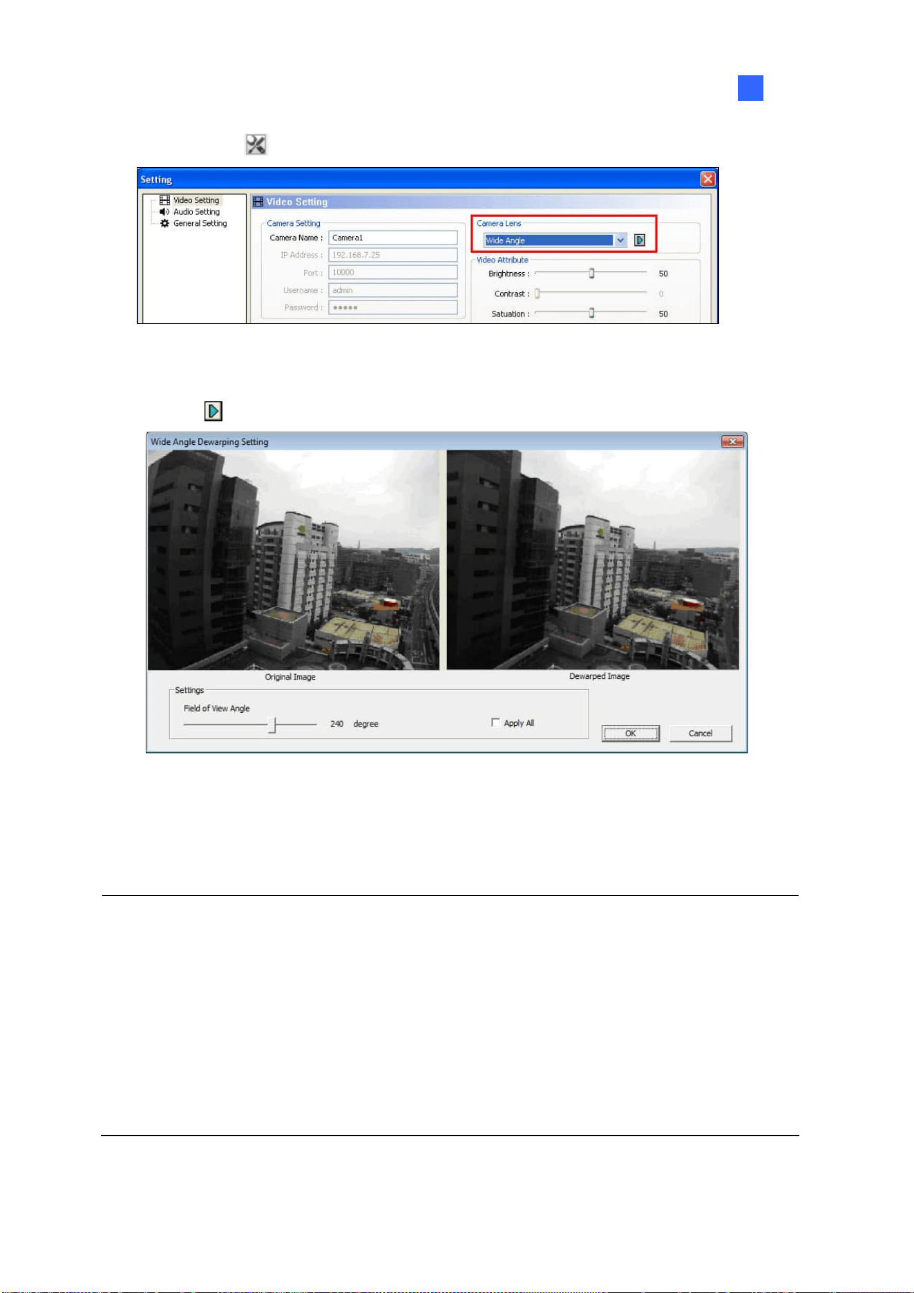
Video Analysis
123
3
2. Click Settings
. This dialog box appears.
Figure 3-44
3. Use the Camera Lens drop-down list to select Wide Angle
4. Click the
button. This dialog box appears.
Figure 3-45
5. Move the slider to adjust the degree of warping. The adjusted view is shown on the right.
6. Click OK. The dewarping is immediately applied on the live view.
Note:
1. This function only applies to live view and does not affect the recorded video. To apply
stabilization to recorded videos during playback, on ViewLog, right-click the desire image >
Effects > Wide angle lens dewarping.
2. If dual-stream IP channels are applied, for better image quality, it is recommended to change the
streaming to single stream before you enable wide angle lens dewarping. This effect does not
support On Demand Display for automatic adjustment of live video resolution in single-channel
division.

124
3.12 Crowd Detection
Crowd detection is used to generate an alert when a crowd of people gathers in a specified area and
exceeds the defined time threshold.
Note: Up to 16 cameras can be configured for this application.
1. Click Home
> Toolbar > Configure > Video process. The Setup dialog box
appears.
2. From the Video Analysis drop-down list, select Crowd Detection, select the desired cameras, and
then click Setting. This dialog box appears.
Figure 3-46
3. Select a camera from the Camera Selection drop-down list.
4. By default the whole camera view is set to be the alarm region. Click the button to clear the
default setting. Click the
button to freely draw the alarm region. To cancel the previously
drawn area, click the
button.
5. To adjust the Crowd Detection sensitivity, move the Sensitivity slider. The higher the sensitivity
value, the more sensitive the system is to detecting crowds.

Video Analysis
125
3
6. To define the minimum ratio of change (in the alarm region) for the alarm to be activated, move the
Ratio of Changes slider to set a value. The smaller the ratio of changes, the more sensitive the
system is to the changes in the camera view.
7. To define the minimum time that a crowd needs to stay for the alarm to be activated. Use the
Tolerance Time of Alarm slider to specify a value or type a number in the blank.
8. Optionally configure the following settings:
Automatically disable alarm: Triggered alarms are automatically disabled after the specified
time (seconds). The default setting is 30 seconds.
Automatically disable alarm when the crowd disperses: Triggered alarms are
immediately disabled when no crowds are detected.
Skip Instant Light Change: Ignores sudden illumination changes to minimize false alarms.
For example, light switches can cause illumination changes suddenly. With the option
selected, the system will ignore significant illumination changes without triggering the alarm
and continue monitoring. See the Note below for possible risk.
Invoke Alarm: Enables the computer alarm when an assemblage is detected. Click the […]
button next to the option to assign a .wav sound file.
Output Module: Activates the output device when a crowd is detected. Select this option and
use the drop-down list to assign an installed output module and a pin number.
Never Recycle: Prevents the system from recycling the event files of crowd detection when
the recycle threshold is reached.
9. You can click Test to test your settings. When an assemblage is detected in the camera view, a
flashing box will appear on its location for warning. If an assemblage cannot be detected, decrease
Ratio of Changes to increase the system sensitivity for detection.
10. Click OK to apply the settings.
11. Start monitoring to run the application. The detected crowd is indicated on the live view with
blinking red and green boxes.
When a crowd of people gathers in the alarm region for the specified time, its location will be
highlighted on live view, the selected alarm or output will be activated, and the event will be recorded
as Crowd Detection in the System Log for later retrieval.

126
Note:
1. For the Skip Instant Light Change option:
When the option is selected, you may be subject to the risk that the system will not generate
an alert whenever the lens of the camera is covered by malice.
This option is not recommended for infrared cameras.
2. Optionally create a schedule for crowd detection to be enabled only at the time periods specified.
For details, see Creating Schedules in Chapter 1.
To manually stop all triggered alerts, click the Tools button
on the triggered channel, select
Reset Alert and select Crowd Detection.
Reset Alert: Disables and resets the triggered alert. After the alert is reset if the crowd remains
gathering over the specified tolerance time, the system will still detect it as a crowd gathering and
keep generating alert.
3.13 Advanced Scene Change Detection
The Advanced Scene Change Detection detects any changes of scene, viewing angle or focus
clearness made by malice in both indoor and outdoor environments.
Note: Up to 16 cameras can be configured for this application.
1. Click Home
> Toolbar > Configure > Video process. The Setup dialog box
appears.
2. From the Video Analysis drop-down list, select Advanced Scene Change Detection, select the
desired cameras, and then click Setting. This dialog box appears.
Figure 3-47

Video Analysis
127
3
3. Select a camera from the Camera Selection drop-down list, and configure these settings:
Mask Region: If necessary, mask off the area on the camera view where any scene change
will be ignored.
Sensitivity: Adjusts detection sensitivity. The higher the value, the more sensitive the system
is for changes in the camera view.
Tolerance Time of Alarm: Sets the duration of scene change before an alarm condition is
activated. Move the slider or type a value (in second) in the blank.
Automatically Disable Alarm: Stops all types of triggered alerts, including sound alarm,
flashing boxes and output module after the specified duration. Disabling the alerts will not
disable alert settings and the detection in progress.
Skip Instant Light Change: Ignores sudden illumination changes to minimize false alarms.
For example, light switches can cause illumination changes suddenly. With the option
selected, the system will ignore significant illumination changes without triggering the alarm
and continue monitoring. See the Note below for possible risk.
Invoke Alarm: Enables the computer alarm when the scene change is detected. Click the […]
button next to the option to assign a .wav sound file.
Output Module: Activates the output device when the scene change is detected. Select this
option and use the drop-down list to assign an installed output module and a pin number.
Never Recycle: Prevents the system from recycling the event files of scene change when the
recycle threshold is reached.
4. You can click Test to test your settings. If the scene change cannot be detected, increase
Sensitivity value to increase system sensitivity to changes in the camera view.
5. Click OK to apply the settings.
6. Start monitoring to run the application.
When a scene change is detected in the camera view for the specified time, its location will be
highlighted in live video, the selected alarm or output will be activated, and the event will be recorded
as Advanced Scene Change in the System Log for later retrieval.
Note:
1. For the Skip Instant Light Change option:
When the option is selected, you may be subject to the risk that the system will not generate
an alert whenever the lens of the camera is covered by malice.
This option is not recommended for infrared cameras.

128
2. To create schedules for Advanced Scene Change, see Creating Schedules, Chapter 1.
To manually stop all triggered alerts, click the Tools button
on the triggered channel, select
Reset Alert and select Advanced Scene Change Detection.
Reset Alert: Disables and resets the triggered alert. After the alert is reset, if the scene change
remains over the specified tolerance time, the system will still detect it as a scene change and
keep generating alert.
3.14 Advanced Unattended Object Detection
The Advanced Unattended Object Detection can generate an alert when any unattended object stays
within the camera view. This function can be applied to both the indoor and outdoor environments.
Note: Up to 16 cameras can be configured for this application.
1. Click Home
> Toolbar > Configure > Video process. The Setup dialog box
appears.
2. From the Video Analysis drop-down list, select Advanced Unattended Object Detection, select
the desired cameras, and click Setting. This dialog box appears.
Figure 3-48

Video Analysis
129
3
3. Select a camera from the Camera Selection drop-down list.
4. If necessary, use the Mask Region function to mask off the area on the camera view where
motion will be ignored.
5. Select Unattended Object Size, and click the Camera icon to pause live images.
6. Outline Min Object Size on the camera view, and select Max Object Size from the drop-down list
and outline the maximum object size on the camera view.
7. To adjust the detection sensitivity, move the Sensitivity slider. The higher the value, the more
sensitive the system is for changes in the camera view.
8. To adjust the minimum time required for the alarm to be activated, adjust the Tolerance Time of
Alarm slider or specify a value in the blank.
9. Optionally configure these settings:
Automatically Disable Alarm: Stops all types of triggered alerts, including computer alarm,
flashing boxes and output module after the specified duration. Disabling the alerts will not
disable alert settings and the detection in progress.
Skip Instant Light Change: Ignores sudden illumination changes and avoids false alarms.
For example, light switches can cause illumination changes suddenly. With the option
selected, the system will ignore significant illumination changes without triggering the alarm
and continue monitoring. See the Note in Crowd Detection earlier in this chapter for possible
risk.
Invoke Alarm: Enables the computer alarm when an unattended object is detected. Click the
[…] button next to the option to assign a .wav sound file.
Output Module: Enables the output device when an unattended object is detected. Select
this option and use the drop-down list to assign an installed output module and a pin number.
Never Recycle: With the option selected, the event files of unattended object detection will
not be recycled when the recycle threshold is reached.
10. You can click Test to test your settings. When an object is left unattended in the camera view, a
flashing box will appear on its location for warning. If the unattended object cannot be detected,
increase Sensitivity value to increase system sensitivity to changes in the camera view.
11. Click OK to apply the settings
12. Start monitoring to run the application. The detected crowd is indicated on the live view with
blinking red and green boxes.

130
When any unattended object is detected in the camera view for the specified time, its location will be
highlighted on live view, the selected alarm or output will be activated, and the event will be recorded
as Advanced Unattended Object Detection in the System Log for later retrieval.
To manually stop all triggered alerts, click the Tools button
on the triggered channel, select
Reset Alert and select Advanced Unattended Object Detection.
Reset Alert: Disables and resets the triggered alert. After the alert is reset if the object remains
unattended over the specified tolerance time, the system will still detect it as an unattended
object and keep generating alert.
Note: Optionally create a schedule for Advanced Unattended Object Detection to be enabled only at
the time periods specified. For details, see Creating Schedules in Chapter 1.

Video Analysis
131
3
3.15 Advanced Missing Object Detection
The Advanced Missing Object Detection can generate an alert when any object disappears from the
camera view. This function can be applied to both indoor and outdoor environments.
Note: Up to 16 cameras can be configured for this application.
1. Click Home
> Toolbar
> Configure > Video process. The Setup dialog box
appears.
2. From the Video Analysis drop-down list, select Advanced Missing Object Detection, select the
desired cameras, and then click Setting. This dialog box appears.
Figure 3-49
3. Select a camera from the Camera Selection drop-down list.
4. Click the
button to outline the regions on the objects you want to detect. To cancel a
previously drawn area, click the
button and outline the area. To remove all previously drawn
areas, click the
button.
5. To adjust detection sensitivity, move the Sensitivity slider. The higher the value, the more
sensitive the system is for changes in the camera view.
6. To change the minimum duration required for the alarm to be activated, move the Tolerance Time
of Alarm slider or specify a value (in seconds) in the blank.

132
7. In the Options section, configure these settings:
Automatically Disable Alarm: Stops all types of triggered alerts, including sound alarm,
flashing boxes and output module after the specified duration. Disabling the alerts will not
disable alert settings and the detection in progress.
Skip Instant Light Change: Ignores sudden illumination changes to avoid false alarms. For
example, light switches can cause illumination changes suddenly. With the option selected,
the system will ignore significant illumination changes and continue monitoring. See the Note
in Crowd Detection earlier in this chapter.
Invoke Alarm: Enables the computer alarm when an object is detected to be missing. Click
the […] button next to the option to assign a .wav sound file.
Output Module: Enables the output device when an object is detected to be missing. Select
this option and use the drop-down list to assign an installed output module and a pin number.
Never Recycle: With the option selected, the event files of missing object detection will not
be recycled when the recycle threshold is reached.
8. You can click Test to test your settings. When the defined object is missing, a flashing box will
appear on its location for warning. If the missing object cannot be detected, increase Sensitivity
value to increase system sensitivity to changes in the camera view.
9. Click OK to apply the settings.
10. Start monitoring to run the application. The detected crowd is indicated on the live view with
blinking red and green boxes.
When any object, which you have outlined the regions for, disappears from the camera view for the
specified time, its location will be highlighted in live view, the selected alarm or output will be activated,
and the event will be recorded as Advanced Missing Object Detection in the System Log for later
retrieval.
To manually stop all triggered alerts, click the Tools button
on the triggered channel, select
Reset Alert and select Advanced Missing Object Detection.
Reset Alert: Disables and resets the triggered alert. After the alert is reset if the object remains
missing over the specified tolerance time, the system will still detect it as a missing object and
keep generating alert.
Note: Optionally create a schedule for Advanced Missing Object Detection to be enabled only at the
time periods specified. For details, see Creating Schedules in Chapter 1.

Video Analysis
133
3
3.16 Text Overlay
You can align camera name, time stamp and triggered input name to different positions for each
channel.
1. Click Home
> Toolbar > Configure > Video process. The Setup dialog box
appears.
2. From the Video Analysis drop-down list, select Text Overlay Setting, select the desired cameras,
and click Setting. This dialog box appears.
Figure 3-50
3. Select a camera from the drop-down list.
4. In the Options section, configure these settings:
Print on video file: Displays camera ID, location name, date and time on recorded videos.
Print on screen (Only for IO alarm): Displays the name of triggered input device on the
camera screen. For this function to work, it is required to map a camera to an input device,
see Other I/O Application Functions in Chapter 6.
Embed Counting Results into Recorded Video: Displays counter results to recorded
videos. For details on establishing a counter alarm, see Object Counting later in this chapter.
Print ASManager Text on Screen: Displays GV-ASManager data such as the license plate
number on the live view and recorded videos. For this function work, it is required to enable
the text overlay setting in GV-ASManager. See 5.6 Using Text Overlay, Chapter 5, in
GV-ASManager User’s Manual.
Note: Text overlay is not supported when standard format codec is enabled. To change this setting,
select Home
> Toolbar > Configure > Camera Install > Settings of the
camera > General Setting and locate the Recording codec format field.

134
Alignment: Select how you want the camera information to be aligned on a camera screen.
Set Font: Click to configure the font, font size, font style and related settings.
3.17 Fisheye View
A fisheye camera allows you to cover all angles of a location with just one camera. The circular fisheye
view can be dewarped into the following four view modes, and you can drag PTZ views to different
angles.
Note: To use the fisheye dewarping function, the graphic card supporting DirectX 10.1 or above is
required.
Quad view: 4 PTZ views 360 degree: 2 PTZ view & 1 360º view
Dual 180 degree: 2 180º views Single view: 1 PTZ view
Figure 3-51

Video Analysis
135
3
3.17.1 Setting up Fisheye View
1. To display the dewapred view, from the Content List, drag the fisheye camera (circular source
image) or one of the dewarpped views to the live view grid.
2. To change the dewarped settings, right-click the fisheye camera from the Content List > Fisheye
Settings. The Fisheye Setting window appears.
Figure 3-52
3. Right-click on the Fisheye Settings window > Fisheye Option to access the following settings:
Camera Mode: You can choose among four view modes.
Quad view: Composed of four PTZ views.
360 degree: Composed of two PTZ views and one 360º panoramic view.
Dual 180 degree: Composed of two 180º views.
Single view: Composed of one PTZ view. This view mode supports the advanced
Picture-in-Picture (PIP) function, which allows you to have a close-up dewarped view
without missing the entire view of surveillance site.
Camera Position: Select Ceiling, Wall or Ground according to installation scenarios.
Adjust Auto Pan Speed At Top-Left Channel: Select low, medium, or high speed to
enable Auto Pan for the PTZ view at the rotation speed of your choice. This option is only
available in Quad view, 360 degree and Single view.
Zoom: Select Zoom In or Zoom Out and then click on the image.
Show Source Video At Top-Right Channel: Display the circular source image in the
top-right quadrant when Quad view is selected.

136
360 Object Tracking: Only available in 360 degree view. Track and highlight detected
motion in live view. For details, see Object Tracking later in this chapter.
Disable automatic zoom adjustment during 360 Object Tracking: Enabled by
default. When disabled, the zoom ratio will be kept at constant as configured.
Disable PIP: Disables the PIP function in Single View mode.
Guard Tour Setting: Only available in Single View mode. Enable to set up a virtual PTZ
tour using the defined preset points on live view. For details, see Virtual PTZ Tour later in
this chapter.
Settings:
Figure 3-53
Wide View: Increases the height of the 180 degree view when camera position is set
to wall mount.
Wide View Disabled Wide View Enabled
Figure 3-54
Frame Rate Control: Limits the frame rate of the fisheye live view to the number
specified here. Select Apply All to apply the frame rate control to other fisheye views.
4. Drag the dewarped fisheye views from the Content List to live view grids for display. You can drag
and drop PTZ view or 180 degree view to adjust the viewing angle.
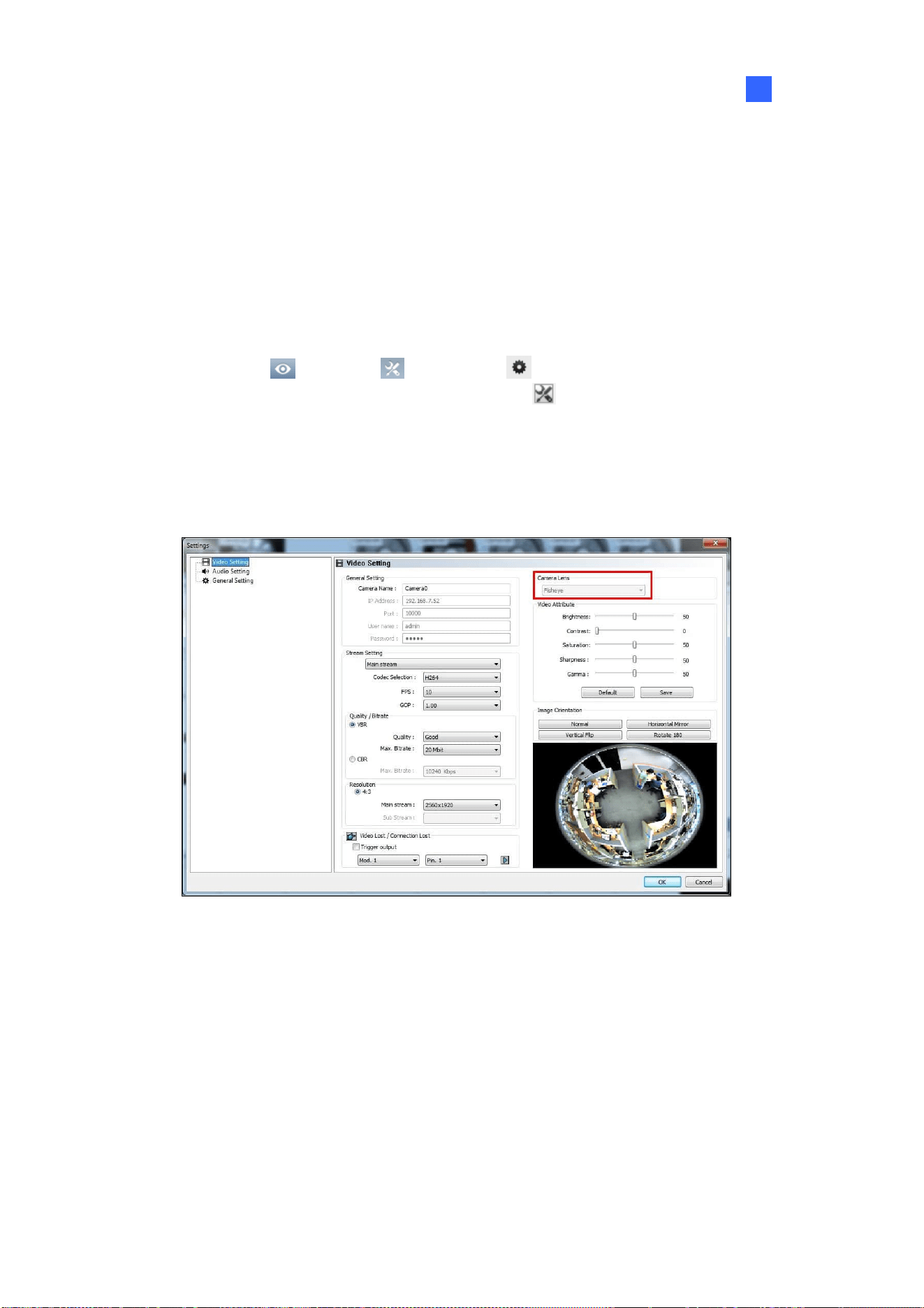
Video Analysis
137
3
3.17.2 Setting up a Third-Party Fisheye Camera
You can also enable dewarping for 3
rd
party fisheye cameras and access fisheye related functions.
1. Make sure you have connected the fisheye camera to GV-VMS. The camera should appear in the
Content List.
2. Select the camera lens type to dewarp the image.
A. Click Home
> Toolbar > Configure > Camera Install. The IP Device Setup
dialog box appears. Then click the Settings button
of the desired camera
.
B. For the camera installed with an ImmerVision IMV1 Panorama Lens, select IMV1
Panomorph using the Camera Lens drop-down list.
C. For other third-party fisheye cameras, select Fisheye using the Camera Lens drop-down
list.
Figure 3-55
3. From the Content List, drag the fisheye camera (circular source image) or one of the dewarpped
fisheye images (e.g. Quad View) to the live view grid.
4. To access fisheye related functions, follow Step 2 to 4, Setting up Fisheye View earlier in this
chapter.
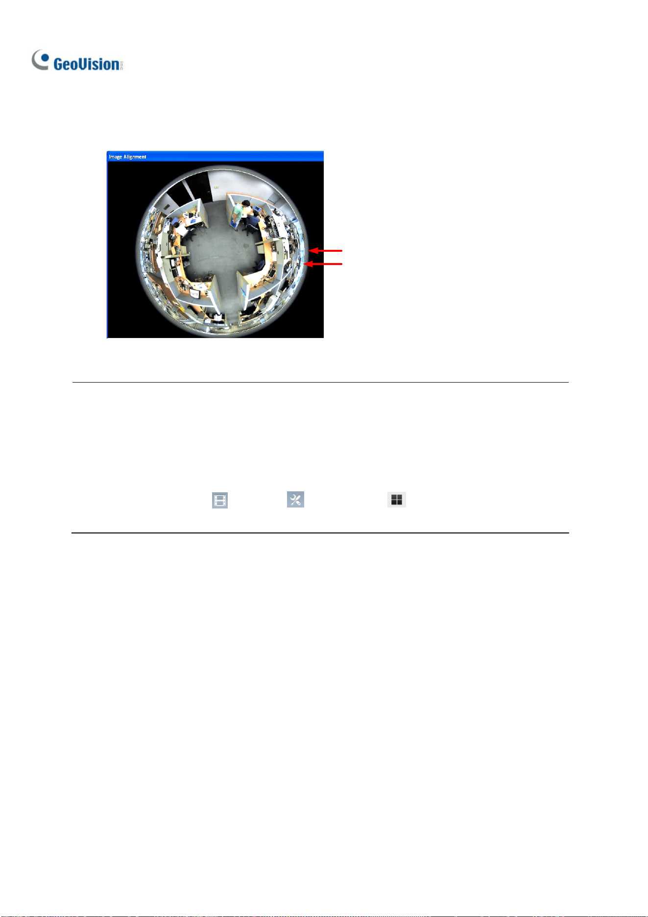
138
5. To adjust the image alignment for optimal results, follow Steps 2 and 3, Setting up a Fisheye View
earlier in this chapter and select Image Alignment. In the dialog box, align the dotted circle with
the outer edge of the camera image, and then align it with the inner edge of the image frame.
Outer Edge
Inner Edge
Figure 3-56
Note:
1. For GV-Fisheye Cameras, the image alignment function is only available on its Web interface.
2. Regardless of the view mode selected here, the hemispherical fisheye source image will be
recorded. When playing back fisheye events in ViewLog, GV-VMS can convert the source image
to different view modes according to your preference. To play back the events in fisheye view
mode, select ViewLog
> Toolbar > Content List
and select a dewarped view of
the camera.

Video Analysis
139
3
3.17.3 Object Tracking
You can set up object tracking in fisheye view to track a moving object. The function is only available
when the view mode is set to 360 degree. When motion is detected in the fisheye view, the top-right
channel will start tracking the moving object, which is highlighted in the 360-degree view at the bottom.
Figure 3-57
1. Set the fisheye view to 360 degree by following Step 1 - 3 in 3.17.1 Setting up Fisheye View and
selecting Camera Mode > 360 degree.
2. On the Fisheye Settings window, right-click the fisheye view > Fisheye Option > 360 Object
Tracking > Advanced Settings. This dialog box appears.
Figure 3-58

140
Mask Region: Use the mouse to outline a mask region where motion is ignored.
Object Size: Click the
button to pause the live view and then use the mouse to outline
the maximum and minimum size of the target object.
Dwell Time of Motion: When the target object stops moving, the highlighted region and the
top-right channel will remain fixed for the number of seconds specified. Any new motion
detected during the dwell time is ignored to prevent the camera view from frequently jumping
from one region to another.
Schedule: Click Schedule to set up the times to start object tracking.
3. To enable object tracking, on the Fisheye Settings window, right-click the fisheye view > Fisheye
Option > 360 Object Tracking > Tracking.

Video Analysis
141
3
3.17.4 Virtual PTZ Tour
You can set up a virtual PTZ tour to monitor important spots of your surveillance site. Before you start,
make sure your fisheye camera has been set to Single View mode.
1. Set the fisheye view to Single view by following Step 1 - 3 in 3.17.1 Setting up Fisheye View and
selecting Camera Mode > Single view.
2. Right-click the fisheye camera on the Content List > Fisheye Settings. The Fisheye Settings
window appears.
3. Right-click the fisheye view on the window > Fisheye Option > Guard Tour Setting. The Guard
Tour Setting dialog box appears along with the Fisheye Settings window.
4. On the Fisheye Settings window, move the live view to a desired starting point for the PTZ tour
by clicking on the inset window at the bottom right.

142
5. Enable the settings, type a name for the current view and click Add. This view point (preset point)
appears under Preset ID.
Figure 3-59
6. Specify the duration for the live view to stay on this preset point (dwell time). The default is 10
seconds.
7. Optionally click Preview to see a preview of the preset point.
8. Click Apply. This preset point is added to Guard Tour Setup.
9. To add more preset points, repeat the steps above.
10. To change the order of the preset points, use the View Order drop-down list to move a preset
point up or down the list.
11. Optionally, click Demo to watch a preview of the PTZ tour.
12. Select OK to start the PTZ tour. To stop the PTZ tour, disable the function on the Guard Tour
Setting.

Video Analysis
143
3
3.18 Video Analysis by Camera
You can choose to process video analysis on the camera instead of on the GV-VMS system.
Currently only GV-BX2600 supports full video analysis functions running on the camera, including
Motion Detection, Intruder, People Count, Missing Object, Unattended Object, Loitering, and
Tampering Alarm functions. For all other camera models, only Motion Detection and GV-3D People
Counter are supported to process on the camera.
Note:
1. You can only choose either the camera or GV-VMS software to process video analysis.
2. The video analysis by camera function does not support GV AI-capable IP cameras (48xx,
58xx and 88xx series).
To access the feature, follow the steps:
1. Click Home
> Toolbar > Configure
>
Video Process.
2. In the Setup dialog box, select IPCVA, select the camera(s), and select Setting.
3. Select which video analysis to process on the camera.
Figure 3-60
4. For motion detection option, click on the arrow
button to activate the following functions:
A. Adjust the level of sensitivity by moving the slider to the desired value, with 1 being the least
sensitive and 10 being the most sensitive.

144
B. Select the area of motion detection by drawing an area on the live view. You may draw 8
areas in maximum.
Figure 3-61
All video analysis events detected on the camera will be recorded in the System Log. For example, if
you set up the People Count function on GV-BX2600, the following analysis results appear:
Figure 3-62
5. For the function of GV-3D People Counter, select
right beside GV-3D People Counter.
A. Type the IP address, ID and Password of GV-3D People Counter. Select Test to see if
GV-3D People Counter is properly connected. Select OK to establish connection.
Figure 3-63

Video Analysis
145
3
B. On the live view of the camera, select Tools
and Monitor. You will see the number of
people going pass the detection area of the camera.
Figure 3-64

146
3.19 Heat Map
With the Heat Map feature, you can see the level of motion intensity in a region, which is represented
by different shades of colors. The visualized traffic data will inform you where people go through and
stay often. This feature is available in both live view and video playback.
Note: Stabilization and Defogging are not supported when Heat Map is enabled.
3.19.1 Enabling Heat Map
1. Click Home > Toolbar > Configure > Video process. The Setup dialog box
appears.
2. From the Video Analysis drop-down list, select Heat Map, select the desired cameras, and click
Setting. The Heat Map Settings dialog box appears.
3. Select a camera from the Camera drop-down list.
Figure 3-65
4. If you want to enable heat map on the live view, select Enable Blending.
Note: If t Enable Blending is unselected, heat map will not be displayed on live view, but heat
map analysis can still be accessed through video playback.
5. To specify a certain area for Heat Map analysis, click the plus sign
, and draw an area on the
live view. To exclude a selected area from analysis, click the minus sign
, draw and crop the
area. To clear the whole selected area, click the X sign
.

Video Analysis
147
3
Note: To draw a shape, click on the live view and draw a line, move the cursor to a different place
and click again. To complete the drawing, connect the end of two lines.
6. You can select from two color modes:
Full-spectral color: The redder the hue, the higher the motion intensity; the bluer the hue,
the less motion intensity.
Single hue progression: The darker the hue, the higher the motion intensity; the lighter the
hue, the less motion intensity.
Figure 3-66: Full-spectral color mode
Figure 3-67: Single hue progression mode
7. Type the number of seconds under Dwell Sec to determine the number of seconds a motion
remains at an area before the Heat Map analysis starts.
8. To preview the effects, click the Test button. To clear all the preview results, click the Reset button.
Time Elapsed shows how much time has passed since your testing has started.
9. Click OK and start monitoring.
10. To clear the heat map results on the live view, click the Tools button
on the channel window
with heat map analysis, click Reset Alert, and click Heat Map.
Figure 3-68

148
3.19.2 Accessing the Heat Map in Recordings
You can freely define a period of time and apply the heat map analysis in recordings.
1. On the ViewLog player, right-click the desired image and select Heat Map. This dialogue box
appears.
Figure 3-69
2. Select the color mode for the Heat Map analysis under Color Scheme.
3. Select the Start Time and End Time under Time Span Setup. You may move the slider under the
image to see the heat map analysis of each hour.
4. Click Apply to see the preview. To clear all the preview results, click the Reset button.
5. Click Save to save an image of the Heat Map analysis.
Note: The time interval for the Time Span Setup must be less than 24 hours.
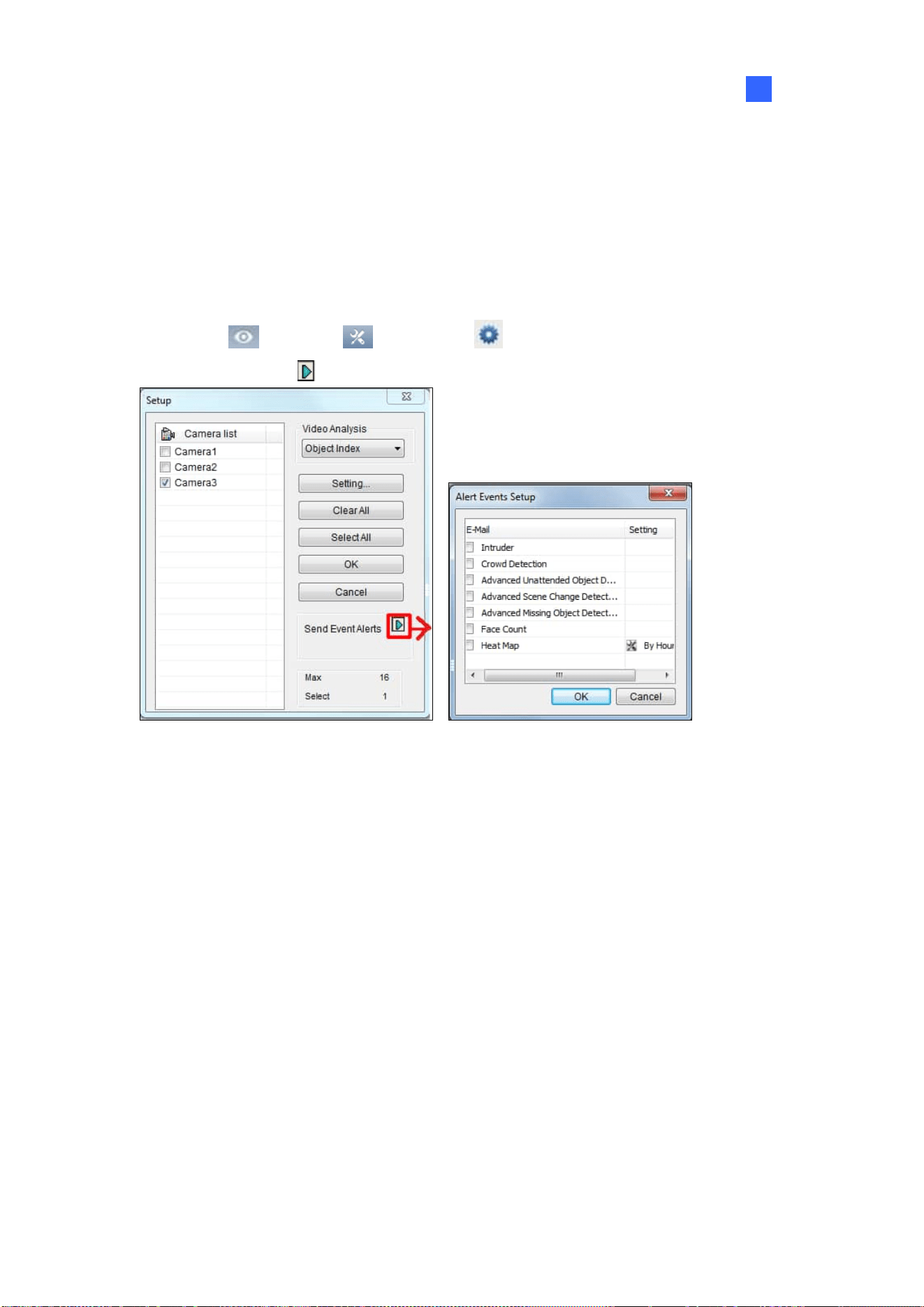
Video Analysis
149
3
3.20 Event Alert through E-mail Notifications
You can choose to be notified of specific types of alert events through e-mail notifications. To fully
activate the function, see 1.6.4 Setting up E-mail Notifications to set up the e-mail server and be sure
that the settings of each type of events are configured in advance.
1. Click Home
> Toolbar > Configure > Video Process.
2. Click the arrow button
next to Send Event Alerts. This dialog box appears.
Figure 3-70
3. Select types of events for e-mail notifications.
4. Click OK to apply the settings.

150
3.21 PTZ Object Tracking
By combining a PTZ and a stationary camera, you can automatically track and zoom on a single
moving object on live view. You can also use only one PTZ camera for object tracking.
3.21.1 Dual-Camera Tracking
To automatically track an object, you need one PTZ camera set for tracking and one stationary camera
set for a fixed view. Install the PTZ camera and the stationary camera in close proximity of each other
so the focus and the camera view of both resemble each other.
Note: The Dual-Camera Tracking function is only supported by GV-PTZ010D, GV-SD220 Series,
GV-SD2723-IR / SD2733-IR / SD2300 / SD2301 / SD2411.
1. Click Home
> Toolbar > Configure > Object Tracking Setup. The Object
Tracking Config dialog box appears.
2. Select a PTZ Camera from the left drop-down list and a Fixed Camera from the right drop-down
list.
3. Select Enable Tracking and start the settings.
Figure 3-71

Video Analysis
151
3
4. Use the Pan, Tilt and Zoom sliders to adjust the current PTZ camera view.
5. Specify Tracking Duration in seconds for every tracking movement.
6. Specify Idle Mode and Idle Time. When the PTZ camera remains stationary for a specified time,
the camera can automatically move to a Home position, a Preset Point, or start an Auto setting.
7. Select Define Detection Region from the drop-down menu. Outline an area on the right (Fixed
Camera) image. You are prompted to confirm Detect Region.
Figure 3-72
8. Select Define Object Size from the drop-down menu. Outline the max and min object sizes for
tracking targets separately on the right (Fixed Camera) image. Every time when finishing the
outlining, you will be prompted to confirm Maximum Object Size or Minimum Object Size.
Figure 3-73

152
9. Click Test and move an object through the camera view to see if its movement is tracked or not.
There are two major settings you have to observe in the test. 1) Tracking: Observe if the target
shown in the defined detection region is being tracked with a highlighted mask, and magnified
automatically in the left (PTZ) image. If not, increase the sensitivity degree. 2) Zooming: Observe
if the target is magnified in the left (PTZ) image clearly. If not, use the Live Tuning buttons to
adjust the level of zooming.
10. Click OK to apply the settings.
11. To start object tracking, click Toolbar
, select Tools and select Object Tracking Start.
Tip: You can interrupt the PTZ tracking and take over the camera control by using PTZ Control
Panel, PC’s keyboard and GV accessories such as GV-Keyboard, GV-IR Remote Control, and
GV-Joystick. When the controlling device or panel is inactive for over 5 seconds, the PTZ camera will
go back for tracking.
Note: When multiple objects are moving at the same time, the camera will track the object with the
largest area.

Video Analysis
153
3
3.21.2 Single Camera Tracking
The Advanced Single Camera Tracking can track a moving object using only one PTZ camera. When
an object moves within the view of camera, the PTZ camera will follow its movement. When the object
is out of view, the PTZ camera can be set to return to a designated position.
Note: The Single Camera Tracking function is only supported by GV-PTZ010D, GV-SD200,
GV-SD220 Series, GV-SD2722-IR / SD2723-IR / SD2733-IR / SD2300 / SD2301 / SD2411.
1. Click Home
> Toolbar > Configure > Object Tracking Setup > Advanced Single
Camera Tracking tab. This dialog box appears.
Figure 3-74
2. Select the camera from the PTZ Selection drop-down list.
3. Select Enable Tracking to start the following settings.
4. Select Support Zoom Function to be able to zoom in and out. Select Normal and the camera will
zoom in once on the moving object. Select Deep Zooming and the camera will zoom in three
times on the moving object.
5. Click the
button to adjust the direction and zoom level of the camera.

154
6. To set the camera to return to its home position or a preset position when no motion is detected for
a certain time period, specify Idle Mode and Idle Time in seconds. Click the
button to
preview the designated position. Note that your camera will need to support home position and
preset position.
7. To outline an area where motion will be ignored, draw an area on the camera view and select Set
Mask on the dialog box that pops up. To remove the mask, draw an area bigger than the mask,
and click Remove Mask.
8. Click Test and move an object through the camera view to see if its movement is tracked or not. If
not, move the Sensitivity slider to increase the sensitivity of motion detection. If the tracking
speed is not fast enough, move the PTZ Speed slider to adjust the speed of PTZ movement. If you
have set up a mask, you can select Enable Mask to display the masked area during the test.
9. Click OK to apply the settings.
10. To start object tracking, click Toolbar
> Tools > Object Tracking Start.
Tip: You can interrupt the PTZ camera tracking and take over the camera control by using PTZ
Control Panel, PC’s keyboard and GV accessories such as GV-Keyboard, GV-IR Remote Control,
and GV-Joystick. When the controlling device or panel is inactive for over 5 seconds, the PTZ
camera will go back for tracking.
Note: When multiple objects are moving at the same time, the camera will track the object with the
largest area.

Video Analysis
155
3
3.22 Panoramic PTZ Object Tracking
With a single GV-Panoramic PTZ Camera (GV-PPTZ) or a pair of GV-Speed Dome Camera and
GV-Fisheye Camera, you can track moving objects on live view. The fisheye camera allows you to
monitor all angles of a location, while the speed dome can instantly point toward an area with just one
click on the fisheye live view. In addition to that, you can also set up object tracking on fisheye live view
to track a moving object automatically. When motion is detected in the fisheye, the speed dome will
start tracking the moving object in the 360 degree view, and the moving object will be highlighted.
To use a pair of GV-Speed Dome Camera and GV-Fisheye Camera for the object tracking, it is
required to pair up the speed dome and fisheye camera first. Right-click on either camera on the IP
Device Setup page, click Select PPTZ Camera, and then click the camera you are pairing to. The
speed dome will be grouped under the fisheye camera in the Content List.
Figure 3-75
Note:
1. To use a pair of GV-Speed Dome Camera and GV-Fisheye Camera for object tracking, install
the cameras in proximity of each other so the focus and the camera view of both resemble each
other.
2. The function is supported by GeoVision speed domes and fisheye cameras only. Refer to our
website for supported models: speed domes and fisheye cameras.
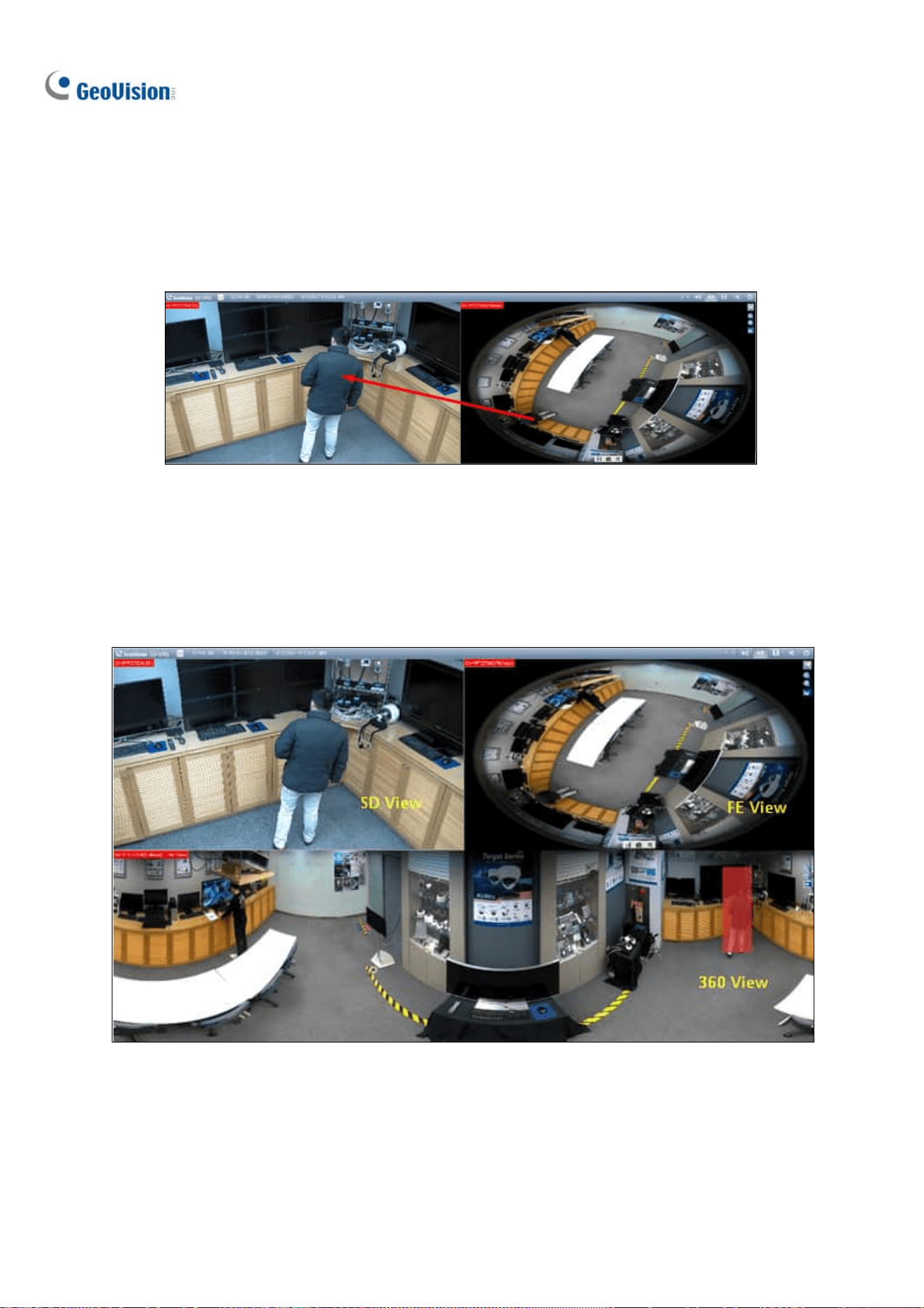
156
3.22.1 Accessing the Live View
To access the live view, drag both the fisheye camera and speed dome channels in the Content List to
the live view grid. Click on the fisheye live view, and the speed dome will turn toward the selected
location.
Figure 3-76
3.22.2 Automatic Object Tracking
The PPTZ Automatic Object Tracking function only works in a 3-division live view. Follow the steps to
create the 3-division live view and to enable the PPTZ Object Tracking in the 360 View.
Figure 3-77

Video Analysis
157
3
1. Click Home, select Toolbar, and select Content List.
2. Under Layout, click Add
, and select Add Layout.
Figure 3-78
3. Type the name of the layout under Name, select Customize, and click OK.
Figure 3-79
4. Click Reset to create a 2 x 2 live view grid, and click OK.
Figure 3-80

158
5. Select the 2 grids at the bottom, click Merge , and click OK to merge the grids.
Figure 3-81
6. When the message “Do you want to assign the cameras to this layout automatically” appears, click
No to assign the camera channels manually instead.
7. Drag 360 View, SD View, FE View (for GV-PPPZ camera) or 360 View, PIP View, Speed Dome
camera (for the paired fisheye and speed dome cameras) to the live view grid.
Figure 3-86
After creating the 3-division live view, go through the steps below to enable the object tracking options.
8. On the Content List, right-click the GV-PPTZ camera or the paired GV-Fisheye camera, and
select PPTZ Setup. The Fisheye Settings dialog box appears.
Figure 3-82

Video Analysis
159
3
9. Right-click on the Fisheye Settings dialog box and select Fisheye Option > Camera Mode > 360
View.
Figure 3-83
10. Select 360 Object Tracking > Advanced Settings to customize the object tracking. For details,
see Object Tracking, Fisheye View earlier in this chapter.
11. Select 360 Object Tracking > Tracking to enable the object tracking.
Figure 3-84
160
3.23 Specifications
Feature Notes
Panorama View
1 GB of RAM required at minimum
4 sets of panorama view for live view
monitoring
Defogging
35 MB of RAM required per channel at
minimum
Maximum of 64 channels
Stabilizer
34 MB of RAM required per channel at
minimum
Maximum of 4 channels
Crowd Detection Maximum of 16 channels
Advanced Scene Change Detection /
Advanced Unattended Object Detection /
Advanced Missing Object Detection
Maximum of 16 channels
Object Counting
7 fps and 6 MB of RAM required per channel at
minimum
Maximum of 32 channels
Privacy Mask
31 MB of RAM required per channel at
minimum
Maximum of 250 detection boxes
The overall size of detection boxes cannot
exceed 102400 bytes.
Face Count Maximum of 16 channels
Object Index / Object Monitor / Face
Detection
7 fps and 16 MB of RAM required per channel
at minimum
Maximum of 16 channels
Object Counting Ye ll ow
Intrusion Alarm Red
Object Index Blue
Face Count Green
Crowd Detection Blinking red and green
Advanced Missing Object Blinking red and green
Detection
Box Color
Advanced Unattended Object Blinking red and green
Specifications are subject to change without notice.
Note: To use two or more of the following functions simultaneously, at least 2 GB of RAM is required:
Advanced Video Analysis, Video Analysis, IP Camera and Pre-Record by Memory.

161
Chapter 4
Video Playback................................... 162
4.1 Playing Back on ViewLog .............................................................. 163
4.1.1 ViewLog Window..........................................................................................164
4.1.2 ViewLog Control Panel ..............................................................................165
4.1.2 Adjusting the Camera View......................................................................168
4.1.3 Bookmarking Video Events in ViewLog ...............................................169
4.1.4 Merging and Exporting Video .................................................................. 170
4.1.5 Saving Images...............................................................................................175
4.1.6 Printing Images ............................................................................................175
4.1.7 Adjusting Distorted Views........................................................................176
4.2 Object Search.................................................................................... 177
4.3 Advanced Log Browser................................................................... 179
4.3.1 Filter Settings ...............................................................................................180
4.4 Remote ViewLog Service .............................................................. 181
4.4.1 Retrieving Recorded Videos from GV-VMS .........................................181
4.4.2 Retrieving Images of Object Index ........................................................ 182
4.4.3 Recording Backup .......................................................................................182
4.4.4 Exporting and Importing Host List ........................................................183
4.4.5 Displaying Sub Stream...............................................................................183
4.5 Single Player ...................................................................................... 184
4.5.1 The Single Player Window ........................................................................ 184
4.6 Specifications.................................................................................... 185
162
Video Playback
Recorded videos can be played back using the following various software applications offered by
GV-VMS. Below summarizes their main characteristic to help you decide which application to use
under a given situation.
Application Description
ViewLog
A full-function player to play back video, search for a video event,
merge and export video and more. See Playing Back on ViewLog in
this chapter.
Object Search
A more convenient tool to search video files recorded on motion or
alarm. See Object Search in this chapter.
Remote ViewLog Service
A program to retrieve files from a remote GV-VMS and it supports most
functions provided by the ViewLog player. See Remote ViewLog
Service in this chapter.
WebCam Server
A server that remotely accesses live view and play back recordings on
your Web browser without installing additional software. See Remote
Viewing in Chapter 7.
Single Player
A player that plays back the backup recorded files with simple and
easy playback functions. See Single Player in this chapter.
CHAPTER
4

Video Playback
163
4
4.1 Playing Back on ViewLog
The ViewLog is a video player that plays back recorded videos without affecting the recording in
process. To launch the ViewLog:
1. Select ViewLog
> Toolbar > Content List . The Content List appears.
2. Select Add
> Import from Live to import current live views to the playback screen. For
details on configuring the ViewLog layout, follow Step 2 to 5 of Arranging Live View Layouts in
Chapter 1.
Figure 4-1
3. Optionally drag and drop more cameras from the Content List to the playback screen.
4. On the timeline, click the arrows or click on the date to select a date from a pop-up calendar.
Figure 4-2
5. Click Play
to start playing back. For details, see ViewLog Control Panel later in this chapter.

164
4.1.1 ViewLog Window
1
2
4
5
7
6
3
Figure 4-3
No. Name Description
1 Camera Name Indicates the camera name.
2 Camera View Displays the playback video.
3 Toolbar
Accesses the player’s various settings. From Setup (Toolbar >
Configure), you can enable/disable text overlay and audio timeline
during the playback, as well as configuring the size of the Preview
window (see ViewLog Control Panel later in this chapter).
4 Recorded Time Indicates the time of recording.
5 Recording Timeline
Indicates the recording date and reflects video recordings.
For details, see ViewLog Control Panel later in this chapter.
6 Playback Panel
Contains typical playback control buttons. For details, see ViewLog
Control Panel later in this chapter.
7. Display All Database Displays the recording timelines of all camera channels.

Video Playback
165
4
4
4.1.2 ViewLog Control Panel
Preview Window
Move the cursor on the timeline to see a preview of recording. Click on the timeline to pause all
channels at the selected time. To change the size of the preview, click Toolbar > Configure >
Setup.
Preview Window
Motion Event
I/O Event
Never Recycle Event
Intrusion Event
Cursor Position
Recording Time
Figure 4-4
Timeline
Round-the-clock Recording
Motion Recording
Playback Scroll
Playback Time
Focused Camera
Next Frame
Play / Pause
Rewind
Previous Frame
Audio
Playback SpeedA to B Mode
Play Mode
Calendar
All Cameras on Layout
Audio Recording
Figure 4-5
Colors in the timeline:
⚫ Red: Motion / Intrusion / IO event recordings
⚫ Blue: Round-the-clock recordings
⚫ Orange: Audio recordings
⚫ Yellow: Recordings retrieved from the SD cards of cameras when reconnecting after a
temporary disconnection
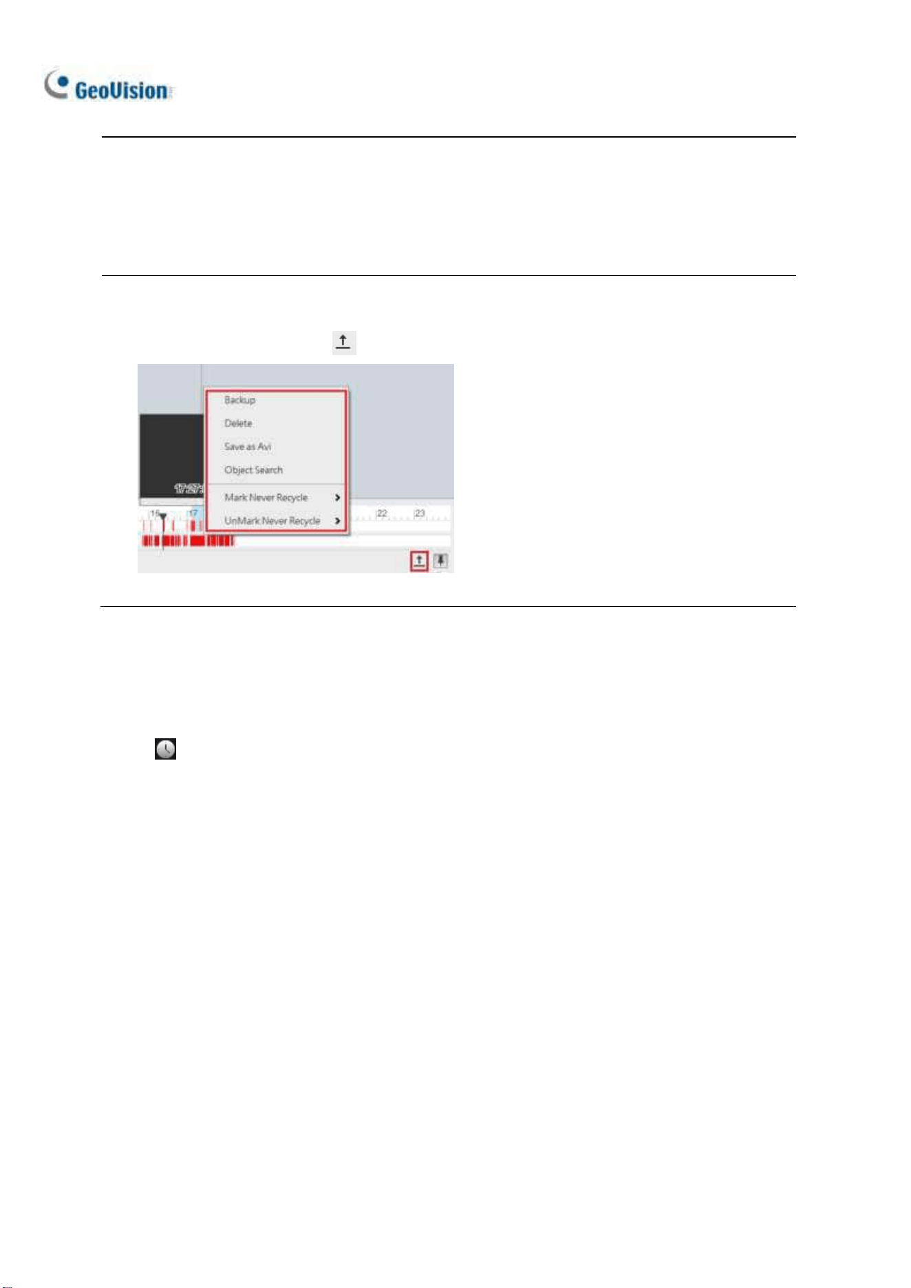
166
Note: Round-the-Clock events are shown as blue, except the following conditions:
1. If Register Motion Event or Intrusion is enabled, the timeline interval of the triggered event
becomes red.
2. If Webcam Service is enabled, the timeline interval becomes red when users log onto GV-VMS
remotely (such as using mobile applications).
Tip:
1. Right-click and drag on the timeline to have a quick access to various functions.
2. Click Display All Database to access the timelines of all camera channels.
Figure 4-6
Playback Mode Option
By default, the ViewLog is set to play back video in the Real Time mode. To change playback modes,
click on the ViewLog Control Panel.
◼ Frame by Frame (without audio): Plays back video frame by frame without audio; however,
playback can be delayed depending on the bandwidth and computer performance.
◼ Real Time: Plays back video on real time. Despite saving rendering time, this method drops
frames.

Video Playback
167
4
4
A to B Playback Mode
When playing back videos, you can set a start frame and an end frame for auto-playing:
1. To set the start frame, click and double-click a time on the timeline.
2. To set the end frame, click and double-click a time on the timeline.
3. The start time and end time are displayed besides A and B as illustrated below.
Figure 4-6
4. Click to play back from frame A to B repeatedly.
5. To cancel this playback mode, click
Changing the Displayed Date on the Recording Timeline
You can directly drag the timeline to search and view recordings of a previous or next day with
recorded events.
1. Scroll the mouse wheel forth to enlarge the timeline. The default display of the timeline is 24 hours.
2. Click and drag the timeline back and forth. The timeline jumps between the recording days.
Figure 4-7

168
4.1.2 Adjusting the Camera View
To adjust the image quality for the recorded videos, right-click on the camera view or click Tools
to access these settings:
Figure 4-8
Print: Prints the current image from the camera view. For details, see Printing Images later in this
chapter.
Effects: Click to apply image effects.
To take a snapshot of the current playback image, select Copy and then open a WORD or
Paint file to paste and save the image.
To undo the last enabled effect, click Undo To Prev Action. To restore to its original video
settings, click Undo All Effects.
Property:
Show Caption: Enabled by default. Shows the camera name.
Keep Image Ratio: Change the camera view to its original ratio.

Video Playback
169
4
4.1.3 Bookmarking Video Events in ViewLog
You can bookmark desired recordings on the ViewLog player.
1. Right-click a camera view and select Add to Bookmark.
2. To access all the bookmarks, click Toolbar
> Tools
> Bookmark. Double-click any
bookmark to move to the corresponding position on the timeline with Playback Scroll.
Playback Scroll
Figure 4-9
3. You can select List Mode to present all the bookmarks in a list.
Note: The bookmarked video events will be marked as Never Recycle in the ViewLog.

170
4.1.4 Merging and Exporting Video
You can merge several videos into a single AVI or EXE file and export it to the local computer.
Note: The maximum size of the exported file is 2 GB. Any file exceeding 2 GB will be split into
another file. A maximum of 16 channels are supported for merging and exporting multiple videos.
1. Click ViewLog
> Toolbar > Tools > Save as Avi. This dialog box appears.
Figure 4-10
2. Click Video Effect and Camera Setting to select the camera channel(s) you wish to export.
3. Drag the timeline to define a starting and ending time of the video(s) to be exported.
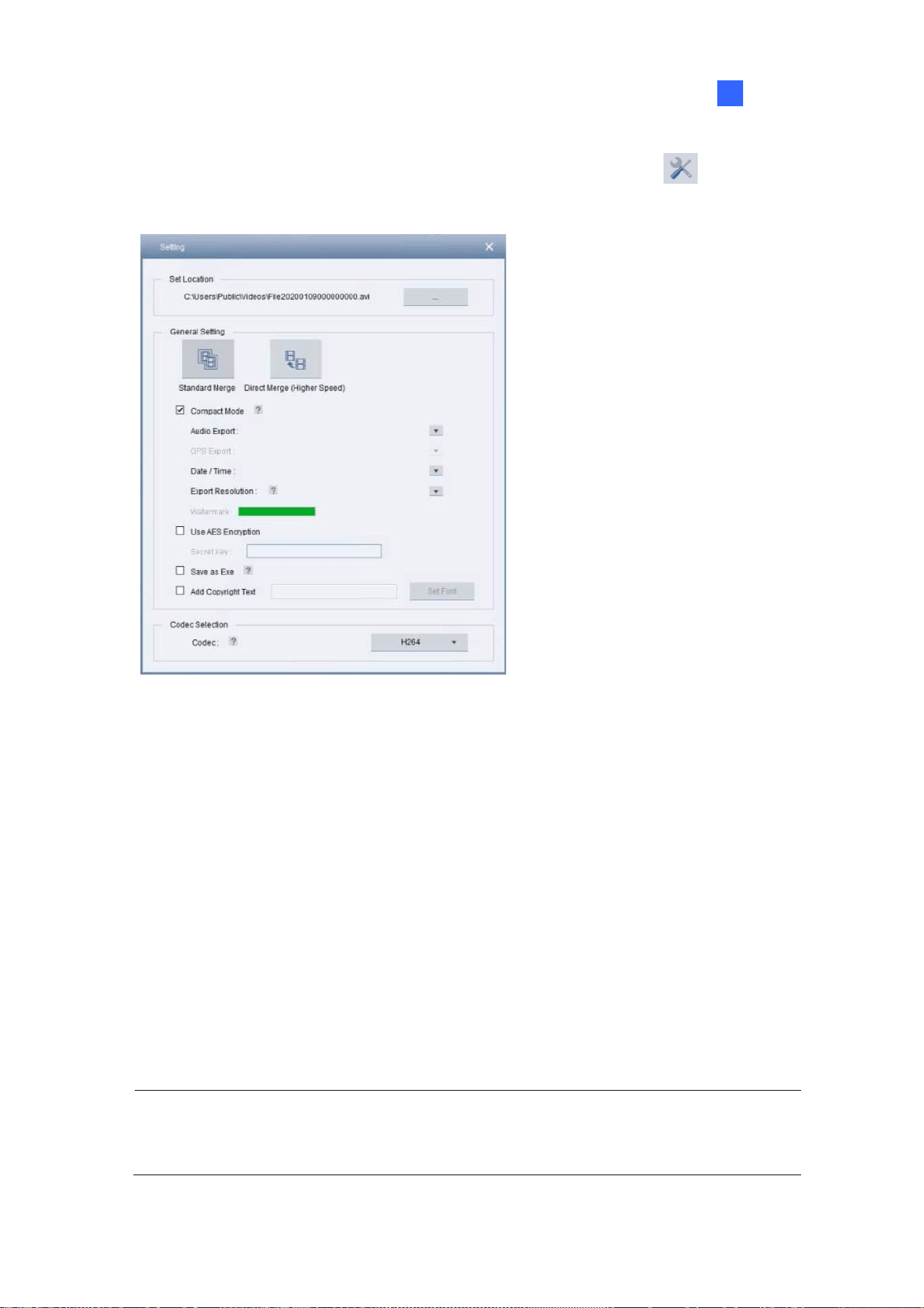
Video Playback
171
4
4. To configure the saving path and format of the exported video, click Setting
. This dialog box
appears.
Figure 4-11
[Set Location] Click […] to assign a saving path.
[General Setting]
Standard Merge: Save a full-length video, containing the images of a single camera or
multiple cameras within the ViewLog, with recorded and non-recorded periods. A blank blue
screen will be displayed during the non-recorded periods. By default, Compact Mode is
selected to merge only the periods with recorded images.
Direct Merge (Higher Speed): Only available when exporting the videos of one channel. It
speeds up the video merging process and saves the video files in the codec in which it was
originally recorded. By default, Compact Mode is selected to save compact video files by
only exporting the key frames.
Note: When using Direct Merge (Higher Speed), the conversion time is significantly reduced,
but you will not be able to customize the following settings: codec selection, privacy mask
recoverability and digital watermark.

172
Audio Export: Select Denoise to remove audio noises from the video, or select Channel
for audio exporting.
Date / Time: Select whether to show date and / or time stamps. You can also select the
stamp position, font type and size and text color on the images.
Export Resolution: Select a resolution for the exported video.
Watermark: Only available when the watermark is applied to the recorded video. Select to
include the watermark in the exported video.
Use AES Encryption: Select and type a 16-digit Secret Key, containing only letters and
numbers, to add additional security protection for the exported video.
Add Copyright Text: Select to stamp user-defined copyright texts to the recording being
exported.
Set Font: Click to set the font type and size as well as the position of the copyright
text on the recording image.
Save as Exe: Select to save files in EXE format to auto-play the files with any third-party
player. Enable this feature to play back video at the computer without installing GeoVision
codec.
[Codec Selection]
Geo H264: A codec created by GeoVision which provides better image quality, higher
frame rates and smaller file size than other standard codecs. When selected, the GeoVision
codec must be installed on the computer playing the exported video. Otherwise export the
files in EXE format to play the video at any computer.
WMV9, H.264 or MPEG4: The standard code allows users to play the video with Windows
Media Player or other third-party video players without using GeoVision codec. When
selected, the Privacy Mask you created in Save as AVI will be disabled.
5. Click the Start icon
to start exporting.
Note: Audio is not supported for videos exported in MPEG4 codec.

Video Playback
173
4
To optionally include other features in the exported video, refer to the following:
Configuring Privacy Mask
To configure the Privacy Mask settings for the exported files, click Setting
and change the Codec
to Geo H264 first.
Figure 4-12
Unrecoverable privacy mask: The block-out area(s) marked in black will not be
retrievable in the exported files.
Recoverable privacy mask: The block-out area(s) marked in red can be retrievable
with the administrator’s ID and password.
To set up the block-out area(s), click and drag on the image and select Add or Delete.
Combining Special Effects
To combine special effects to the exported video, click the Video Effect + Camera Setting icon
and select the desired effects for each of the cameras selected.
Figure 4-13

174
Retaining Recoverable Block-out Areas
For recorded videos with Privacy Mask settings, by default, you can see the recoverable block-out
area(s) created in Main System when logging in with the administrator account. To retain the block-out
area(s) before exporting recorded videos, type a random ID and password in the fields or leave the
fields blank. For details on Privacy Mask, see Privacy Mask Protection in Chapter 3.
Figure 4-14
Note: Only the administrator can set up the ID and password to retrieve or retain the recoverable
block-out area(s). To grant access right to Power Users and Users, see Granting Access Privileges to
Recoverable Areas in Chapter 3.
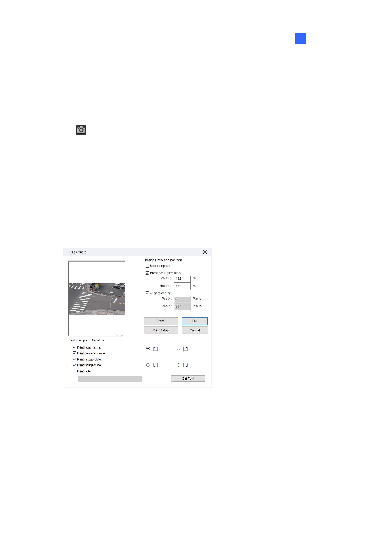
Video Playback
175
4
4.1.5 Saving Images
You can take a snapshot and save the current camera view as an image file while the recorded video
is being played back.
1. Click
from a camera channel on the ViewLog. The Save As dialog box appears.
[Stamp Text on the Image] Select to add text(s) to the image. Selecting Transparent Text will
create the stamps in transparent text.
[The image] Click on the image at the bottom to preview the stamp text. Click on the image again
to close the preview window.
2. Name the file, select a file format and assign the location to save the image file.
4.1.6 Printing Images
1. Right-click a camera channel on the ViewLog and select Print. This dialog box appears.
Figure 4-15
[Image Ratio and Position] Adds a template or changes the size of the image and its position on
the page.
[Text Stamp and Position] Adds texts to the printed image. To include a note below the image,
select Print note and type a note in the blank space below, up to 64 characters.
2. Click OK to save the settings or Print to print out the page.

176
4.1.7 Adjusting Distorted Views
When viewing videos on the ViewLog player, images may be curved near the corners. Correct this
distortion using the Wide Angle Lens Dewarping feature.
1. Click ViewLog
> Toolbar > Configure > Effect > Wide Angle Lens Dewarping.
2. Select the cameras to apply Wide Angle Lens Dewarping.
3. To adjust the degree of adjustment, click the
button. This dialog box appears.
Figure 4-16
4. Move the slider to adjust the degree of warping. The adjusted view is shown on the right.
5. Select Apply All to apply the setting to all the cameras selected.
6. Click OK. The cameras are immediately dewarped.

Video Playback
177
4
4.2 Object Search
Object Search allows you to define the regions of interest on recorded videos to search for missing
objects, unattended objects and motion events, as well as counting the number of objects entering and
leaving the defined regions.
1. Select ViewLog
, click the desired channel and select Toolbar > Tools > Object
Search. This window appears.
Figure 4-17
2. Define a time range for search. And click the Play button to display images of the defined time
range.
3. Select an event type from the drop-down list
.
4. Click Setting
.

178
5. Click on the image to add detection regions or define object sizes. You can also adjust the
sensitivity level of the added detection regions.
Figure 4-18
6. Click Just Key Frame
to search only key frames if necessary.
7. Click Search
.
The search results are shown in blue on the timeline.
8. Double-click a frame or click the Play button to view the event.
Figure 4-19

Video Playback
179
4
4.3 Advanced Log Browser
With the Advanced Log Browser, you can search for log data of events, system activities, user
activities, Object Counting events and more. For live system logs, see System Log in Chapter 1.
1. Click ViewLog
> Toolbar > Tools > System Log > Advanced. The Open
Database dialog box appears.
2. Specify a time range and click OK. All events within the specified range are displayed on the
Advanced Log Browser.
Controls on the Advanced Log Browser
Figure 4-20
No. Name Description
1 Open Opens an event log.
2 Reload
Select Reload All Table or Reload Current Table to refresh loaded data.
3 Filter
Defines the search criteria. See Filter Settings later in this chapter.
4 Backup
Select All Tables to back up all log data, or selects Current Table to back up
the current log table you are at. By default, audio and video are enabled for
backup.
5 Print Prints the current log table.
6
Filtering /
Cancel Filtering
Only available when filtering starts. Click to cancel the filtering. After the
filtering is complete, this icon appears dimmed.
7 Counter Table
Only available when selecting Counter as the Log Type. Click to display the
sums of the In and Out counting numbers of cameras with counting function.
8 Log Type
Select to display log of the following type: monitor, login, system, counter,
merge, delete, backup, I/O, notifications, playback, CMS, and POS.

180
4.3.1 Filter Settings
You can define filter criteria to search for the desired log data. You can also import pre-defined filter
settings for the log search, or save current filter settings for future use.
1. On the toolbar, click the desired log type, click the Filter button (No. 3, Figure 4-20) > Default
Filter. This dialog box appears.
Figure 4-21
2. Define the filter criteria, such as a specific camera, an event and a time range.
3. To search for the log data recorded during Daylight Saving Time, select DST Rollback.
4. To add more filter criteria, click Add New Command and repeat Step 2.
5. Optionally click Export to save the current settings to another location, or click Import to apply
other filter settings.
6. Click OK to display the filter results.
Tip: Next time when you want to use the same exported settings, click the Filter button >
Favorites, and select the name of the export file.
Note: The default Export path is :\GV folder\Syslog_Favorites\Monitor. If you change the saving
path, the name of the export file will not be listed in the Favorites option.

Video Playback
181
4
4.4 Remote ViewLog Service
You can retrieve the files from a remote GV-VMS through the network using the Remote ViewLog
Service.
GV-Remote ViewLog V2:
supports most of the functions provided by the ViewLog, such as Backup, Save as AVI, Object
Search, Database Files Backup, described earlier in the chapter.
is capable of disabling camera connections under heavy network load
can back up recordings from a remote GV-VMS
4.4.1 Retrieving Recorded Videos from GV-VMS
1. On GV-VMS, click Home > Toolbar > Network > Control Center Server >
Remote ViewLog Service to allow remote access.
2. Download GV-Remote ViewLog V2 to a PC from GeoVision’s website
.
3. Run GV-Remote ViewLog V2 and create a Remote ViewLog account. After creating an account,
the Add New Host dialog box appears.
4. In the Host Type, select DVR / NVR / VMS.
5. Type the Name (for reference), IP Address, Account and Password of GV-VMS. Only modify
the default port 5552 if necessary.
6. Click OK.
For details, see GV-Remote ViewLog V2 Guide
.
Note: GV-Remote ViewLog V2 has enhanced user interfaces compared to previous GV-Remote
ViewLog. Currently, not all the features in GV-Remote ViewLog are available on GV-Remote ViewLog
V2.

182
4.4.2 Retrieving Images of Object Index
The images of Object Index include the Object Index, Face Detection and Video Snapshot. With the
Remote ViewLog Service, you can retrieve all the Object Index images from a GV-VMS through the
network.
1. On the toolbar, select Tools
> Search Object Index.
2. On the Object Index Search window, select the desired camera and file date for playback.
3. Click the Refresh button
to refresh the date and time.
4. To play images with the ViewLog player, double-click the desired frame on Object Index List.
4.4.3 Recording Backup
Using the Remote ViewLog Service, you can back up files from remote GV-VMS. When the file
transfer is interrupted by a network error, you can even resume backup.
1. To back up the recordings, on the toolbar, select Tools
> Backup.
2. When the backup is interrupted, this message will appear: There are x file(s) couldn’t be backup.
Do you want to keep a log file and backup them later?
3. Click Yes. You will be prompted to save the partial backup file as *lv format.
4. To resume backup, click the Resume button at the bottom of the Backup dialog box and locate the
partial backup file to continue.
For details, see Backing Up Recorded Files in Chapter 5.

Video Playback
183
4
4.4.4 Exporting and Importing Host List
You can export and import the host list to and from another GV-Remote ViewLog. Click the Tools
button under Camera List to access these functions.
Figure 4-22
4.4.5 Displaying Sub Stream
To reduce network latency when playing back multiple channels, you can choose to display the sub
stream of smaller image size from the connected hosts if the dual-stream recordings are available. To
do so, on the toolbar, click Display
> Display Dual Stream First.

184
4.5 Single Player
When backing up recorded files, you can choose to include the ViewLog player or Single Player (see
Backing up Recorded Files in Chapter 5). Compared to the ViewLog, the Single Player provides
simpler and easier playback functions. To play back the recorded videos using the Single Player, open
the backup folder and run GVSinglePlayer.exe.
4.5.1 The Single Player Window
Click Files > Open File to select the file you wish to play back. To play back multiple recorded files
together in up to 16 screen divisions, click Files > Open Folder to select the folder that collects
several camera recordings.
Figure 4-23

Video Playback
185
4
4.6 Specifications
Feature Notes
Support for Defogging Yes (64 channels)
Support for Stabilizer Yes (64 channels)
Support for PIP View Yes
Support for PAP View Yes
Support for Panorama View Yes (4 sets of Panorama View )
Videos Exported as .AVI Files Yes
Object Search Yes
Support for Fisheye View Yes

186
Chapter 5
Backup, Deletion and Repair.............. 187
5.1 Backing up Log Data ....................................................................... 187
5.2 Backing up Recorded Files ........................................................... 188
5.3 Deleting Recorded Files................................................................. 191
5.4 Repairing Damaged File Paths..................................................... 192
5.5 Repairing Damaged Video Files................................................... 193

187
Backup, Deletion and Repair
This chapter explains how to back up and delete video/audio files on the hard disk. Video files can be
copied to external storage media, such as CD-R, DVD, MO, or ZIP drives.
5.1 Backing up Log Data
Using the System Log, you can back up all log data or filtered data based on criteria.
1. Click ViewLog
> Toolbar > Tools > System Log > Advanced. The Open
Database dialog box appears.
2. Specify a time range and click OK. Events recorded during the specified range are displayed on
the Advanced Log Browser window.
3. Click Backup
on the toolbar. The Customer Database Export dialog box appears.
[Table Option] Select All Tables to back up all log data or Current Table for the log table you are
currently at.
[Export with Video/Audio data] Backs up video/audio attachments with log data.
4. Click OK. The Backup dialog box (Figure 5-1) appears.
5. In the Media section, select the method and destination to back up the log files and click OK to
back up.
Note:
1. To back up the filtered data, use the Filter function to define search criteria first. See Filter
Settings, Advanced Log Browser in Chapter 4.
2. To open the backup data, run EZSysLog.exe from the backup file.
CHAPTER
5

188
5.2 Backing up Recorded Files
1. Click ViewLog > Toolbar > Tools > Backup. This dialog box appears.
Figure 5-1
2. Select a destination media to back up files.
[Media]
Using Hard Disk: Click the […] button to select the desired hard disk.
Backup Folder Name: Type a desired name for the backup folder.
Using CD/DVD/BD: Click to back up files to the CD or DVD media using the third-party
software.
Click the […] button to assign the desired burning software (.exe file). After clicking OK
on the Backup dialog box (Figure 5-1), the system will ask you to paste the backup files
to the CDR-Writer program, and call up the assigned burning software for you to paste
and backup files.
If Nero software of version 6.6.0.14 or later is installed, you can directly burn the files
onto CD/DVD without assigning the burning software and pasting the backup files to the
CDR-Writer program.
If Nero software of version 7.0 or later is installed, you can directly burn the files to
blu-ray disc.

Backup, Deletion and Repair
189
5
Using OS-Burning: It burns files using the inbuilt software of the operation system onto the
DVD, CD or blu-ray disc. Note that your hard disk needs at least 1 GB buffer space.
[Media Information] Indicates free and used space on CD/DVD media or the local disk.
3. Click the Add Time Frame button to define a time period and which files to back up.
Figure 5-2
[Time Period] Specify the time periods for backup.
[Information] Indicates the number of backup files and their total size. (Total MDB refers to the
System Log files.)
[Advanced Setting]: Click
to choose which files to back up:
Database Files: Backs up the System Log files.
Object Index Files: Backs up the Object Index files.
Never-Recycle Events only: Only backs up the never-recycle events.
Unmark these events to be recycled after the backup is complete: After the backup is
complete, the never-recycle events will be unmarked for recycling.
Include daylight saving rollback events: Backs up the events recorded during Daylight
Saving Time.
Bookmarked files: Backs up the bookmarked files.

190
[Select Camera(s)] Select the camera(s) for backup. The number of video and audio files of
each camera is indicated respectively, e.g. “Camera 1 1+0” means Camera 1 has 1 video file and
0 audio file.
Video + Audio drop-down list: Select the types of video events for backup.
4. Click OK to add the schedule. You can repeat step 3 to create up to 10 periods of time.
5. To include the player to the backup files, select Include Player at the right bottom of the Backup
dialog box and select ViewLog or Single Player. By default, ViewLog is selected. If no player is
selected, you can only play the backup files at the computer installed with GeoVision codec.
6. Click OK on the Backup dialog box to start the backup.
Note:
1. If you are unable to record a CD, make sure the CD recording is enabled in your CD burner:
open My Computer, right-click the CD Drive icon, click Properties, click the Recording tab,
and check Enable CD recording on this drive.
2. For details on the ViewLog player and Single Player, see Chapter 4 Video Playback.

Backup, Deletion and Repair
191
5
5.3 Deleting Recorded Files
1. To delete files using the ViewLog, click ViewLog > Toolbar > Tools > Delete. This
dialog box appears.
Figure 5-3
2. Define the time period for file deletion.
3. Uncheck the cameras, which you don’t want to delete the files of.
4. Use the drop-down list to select the types of events to be deleted, e.g. video, audio or both
together.
5. To delete the never-recycle events, select Include Never-Recycle Event.
6. To delete the events recorded during Daylight Saving Time, select Include Day Light Saving
Time Rollback Event.
7. Click the Delete button.
Note:
1. To view the history of file deletion, click ViewLog
> Toolbar > Tools > System
Log > Monitor Table, and click the Delete tab.
2. To view the storage path and total file size of a camera, right-click the camera and select Event
View on the Delete dialog box.

192
5.4 Repairing Damaged File Paths
Use the Delete function (see Deleting Recorded Files earlier in this chapter) to correctly delete video
and audio files. If you move or delete video files using Windows Explorer or Windows File Manager,
GV-VMS will not be able to detect this change. But as long as these files are still stored in the hard
drives and are detectable by Windows operating system, you can use the Utility to restore these
misplaced and missing recorded files back to their default paths. This Utility comes with the installation
of Main System. Follow these steps to repair the paths.
1. Go to the Windows Start > All Programs > GV-VMS folder > Repair Database Utility.
2. When the Select Camera for Repair Database dialog box appears, select the cameras that require
database repair and click OK. This dialog box appears.
Figure 5-4
3. If your recorded files exist only in the predefined recording path, click the Use Default Path button
to rebuild the file path in the predefined recording hard drive only.
4. If your recorded files scatter across different hard drives, click the Search Hard Disk button to
allow more time to rebuild these file paths in the hard drives connected to GV-VMS.
Note:
1. The repair and the search function will not apply to the files that have been renamed manually.
2. Use this Utility to repair your database if any of the following scenarios occurs in the ViewLog:
a. A question mark appears right before a video file in the Video Event list.
b. When you select a file and click the Playback button, no video is displayed.

Backup, Deletion and Repair
193
5
5.5 Repairing Damaged Video Files
If the computer has been shut down improperly, e.g. due to power failure, use this function to repair
damaged video files.
Tip: When a computer has been shut down improperly, the first thing you do before starting GV-VMS
is to run Repair Database Utility. After running the Utility, go to the ViewLog and check video events.
You should be able to play all video files at this step. However, if you see a question mark after
clicking on a file, the problem may be that its recording process was interrupted. To repair the file, run
the AVI Repair Utility and follow the steps below.
1. Double-click AVIRepairAPI.exe in the GV folder. This dialog box appears.
Figure 5-5
2. Click the Browse button to find the damaged video file.
3. If you know the codec and resolution of the file, select Manual, select Compression Type and
type Resolution. Alternatively, select Auto but it takes longer time to repair with this selection.
4. Click the Repair button to start.
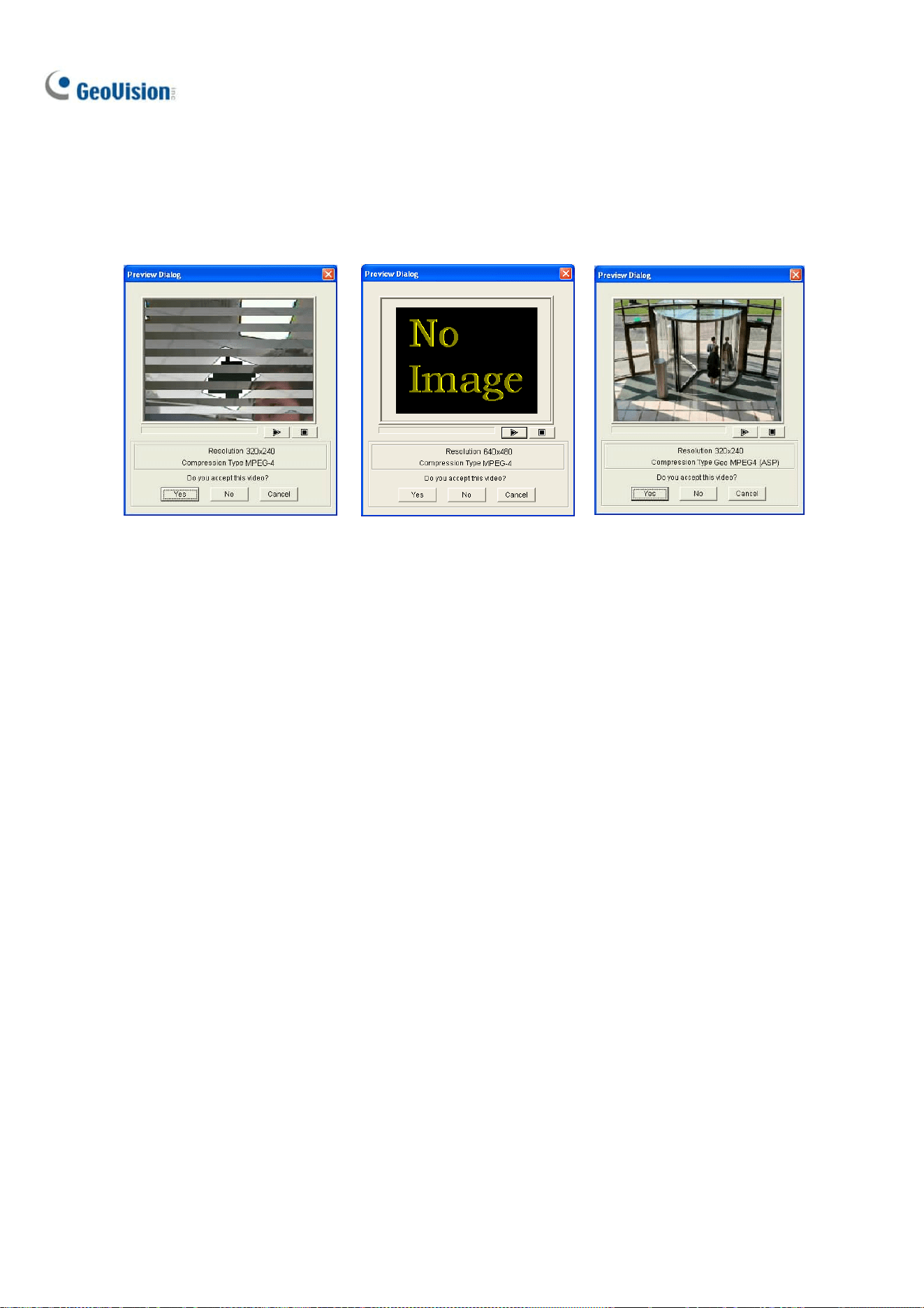
194
5. You may see the distorted image or No Image on view screen if an incorrect codec and resolution
were chosen. Click No for the next combination until a complete image appears.
Distorted Image No Image Complete Image
Figure 5-6 Figure 5-7 Figure 5-8
6. When a complete image is displayed, click the arrow button to preview the file.
7. Click Yes to start the repair.
8. Click Yes to overwrite or No to save this file to another path. Note if you choose No at this step,
remember to run Repair Database Utility again after exiting this program.

195
Chapter 6
I/O Applica
tions .................................. 196
6.1 Setting I/O Devices........................................................................... 196
6.1.1 Adding I/O Devices ......................................................................................197
6.1.2 Setting up Input and Output Devices....................................................198
6.1.3 Latch Trigger.................................................................................................199
6.1.4 Keeping Last Toggle Status..................................................................... 201
6.1.5 Setting up PLC I/O devices .......................................................................203
6.2 Advanced I/O Applications............................................................. 205
6.2.1 Setting up Actions upon Input Trigger ................................................. 206
6.2.2 Moving PTZ Camera to Preset Points upon Input Trigger ............. 207
6.2.3 Setting up Momentary and Maintained Modes ..................................208
6.2.4 Deactivating Alarm and Alert upon Input Trigger ............................209
6.2.5 Other I/O Application Functions ............................................................. 210
6.3 I/O Devices in Content List ............................................................ 211
6.4 Visual Automation ............................................................................ 212

196
I/O Applications
This chapter discusses how you can set up and control the I/O devices connected to GV-VMS. I/O
applications include these features:
Record videos, send e-mail notifications and trigger outputs upon input trigger
Move PTZ camera to a preset location on input trigger
Support access control systems of Momentary and Maintained modes
Visual automation to intuitively trigger an output by clicking on the camera view
6.1 Setting up I/O Devices
To connect the I/O device to the computer of GV-VMS, you may need additional devices: GV-Net,
GV-Net Card, GV-NET/IO Card or GV-I/O Box. For details, visit GeoVision website
.
To set up I/O devices on GV-VMS, click Home
> Toolbar > Configure >
Accessories (if available) > I/O Device (if available) > I/O Device Setup. This dialog box appears.
Figure 6-1
Note: The Accessories option only appears when GV-Keyboard or GV-Joystick has been set up on
GV-VMS. The I/O Device option only appears after at least one I/O device has been added.
CHAPTER
6

I/O
Applications
197
6
6.1.1 Adding I/O Devices
To add an I/O device to GV-VMS, click the Add button in I/O Device Setup dialog box.
Figure 6-2
There are three ways to add an I/O device:
I/O Box (USB): Select if GV-VMS is connected to the GV-I/O Box through USB connection.
1. Select the type of Device connected.
2. Select the COM port used to connect the device.
3. Assign an Addr. number to the device. Start by setting the first device to 1, and then assign a
different address for every new device added.
IP Device: GV-VMS can remotely control the I/O devices connected to GV-IP Devices through
network connection. Select the GV-IP Device with I/O devices installed and click the
button.
I/O Box (IP): GV-VMS can remotely control the I/O devices connected to GV-I/O Boxes through
network connection.
1. Click the Search button to search for available devices under LAN or click the Add button to
manually type the connection information of the device.
2. Select the device and click the
button. Type the User Name and Password if
needed.

198
6.1.2 Setting up Input and Output Devices
After adding the I/O device, enable the input and output device. For GV-I/O Boxes connected through
USB, you can configure the signal type on GV-VMS. For GV-IP Devices and GV-I/O Boxes connected
through a network, you will have to configure the signal type on the device’s Web interface.
[Input X] Click the Arrow buttons to select the input device and click Enable.
Select Input Apply to all Inputs
Sync Web UI
Figure 6-3
Name: Name each input pin. The left Arrow button allows you to sync the name with that on the
I/O device’s Web interface.
Signal Type: Select a signal type for your input device: NO (normally open), NC (normally close)
or Latch Trigger. For details on Latch Trigger, see Latch Trigger later in this chapter.
[Output X] Click the Arrow buttons to select the output device and click Enable.
Figure 6-4
Name: Name each output pin. The left Arrow button allows you to sync the name with that on the
I/O device’s Web interface.
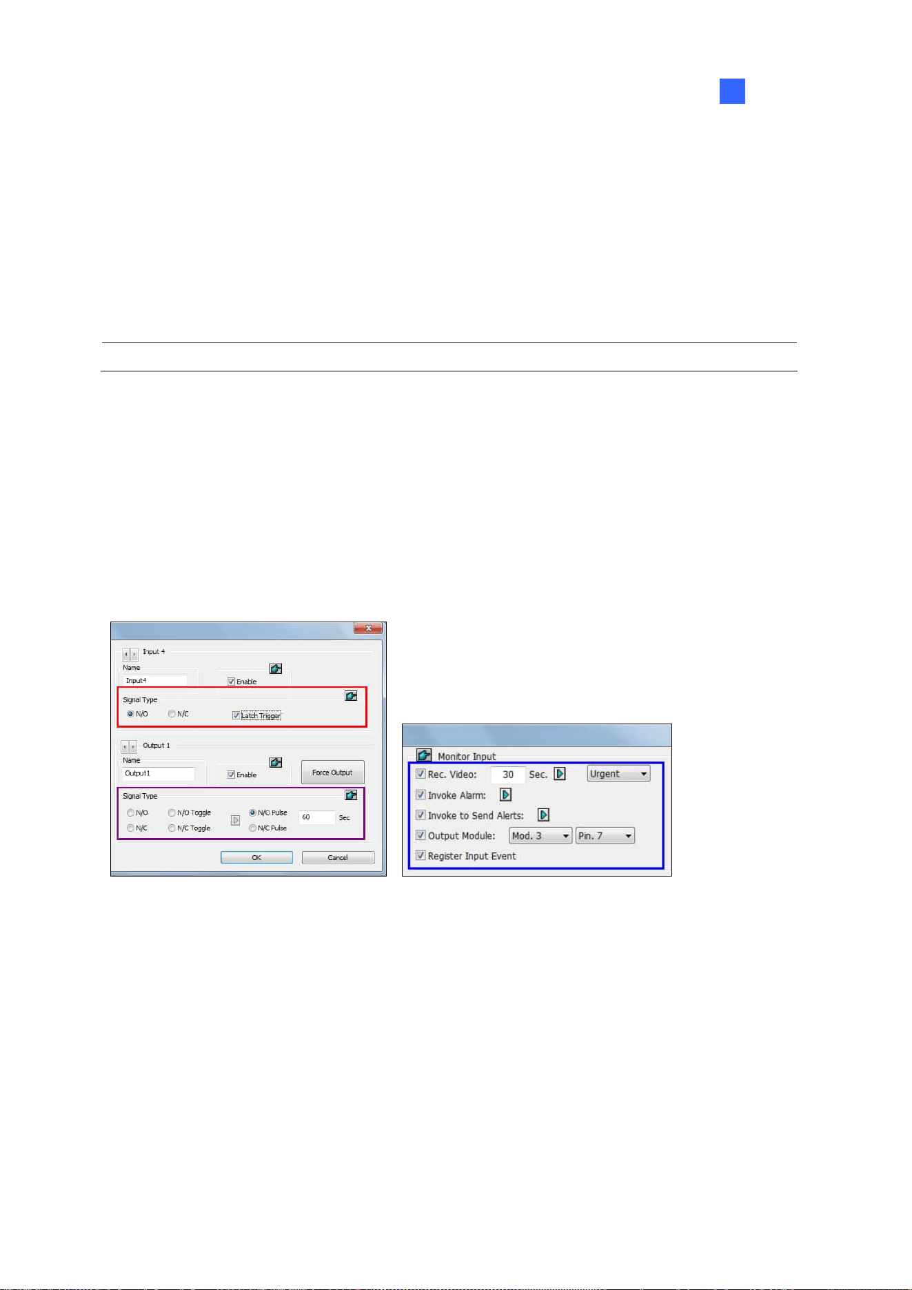
I/O
Applications
199
6
Force Output: Click to test signal to the selected device.
Signal Type: Select a signal type: N/O (Normal Open), N/O Toggle, N/O Pulse, N/C (Normal
Closed), N/C Toggle, and N/C Pulse. For Toggle output type, the output continues to be triggered
until a new input trigger ends the output. For Pulse output type, the output is triggered for the
amount of time you specify in Sec field.
Keep Last Toggle Status: See Keeping Last Toggle Status later in this chapter.
Note: PTZ camera and I/O devices cannot be assigned to the same port at the same time.
6.1.3 Latch Trigger
Instead of constant output alarm in N/O and N/C during the input trigger, the Latch Trigger option
provides a momentary output trigger.
Setting up Latch Trigger
In the I/O Device dialog box (Figure 6-1), select Latch Trigger.
I/O Device Setup I/O Application Setting
Figure 6-5
Application Example
In the above scenario, Input 4 is set to N/O and Latch Trigger. When Input 4 is triggered:
The camera starts recording for 30 seconds using the frame rate settings for Urgent Event and
stops itself when the next input triggers (see the Rec Video option in the blue box).
Computer Alarm sounds once (see the Invoke Alarm option).
The output (Module 3, Pin 7) is triggered simultaneously based on the Latch Trigger mode (see
the illustrations below).

200
The following illustrations can help you understand different output signals (see purple square in the
above dialog box) working with the Latch Trigger option.
1. N/O (Normal Open) + Latch Trigger
Once the input triggers the output, the output will be triggered for a short moment and then turn off
itself.
Input
Output
N/O N/O N/O
N/O N/O N/O
N/CN/C N/CN/C
2. N/O Toggle + Latch Trigger
Once the input triggers the output, the output will keep triggering until a new input trigger.
Input
Output
N/O N/O N/O N/O
N/CN/C N/CN/C
1st Input Trigger 2nd Input Trigger
3. N/O Pulse + Latch Trigger
Suppose you set the Pulse time to 60 seconds. Once the input triggers the output, the output will
remain ON for 60 seconds before turning off itself.
Input
Output
N/O N/O N/O N/O
N/CN/C N/CN/C
60
sec
60
sec

I/O
Applications
201
6
6.1.4 Keeping Last Toggle Status
This feature can memorize the current output state when the monitoring is stopped or the system is
restarted. For example, if the output device is a light, the triggered light will remain ON when you stop
monitoring.
Setting up “Keep Last Toggle Status”
In the I/O Device dialog box (Figure 6-1), select N/O Toggle or N/C Toggle, and click the Arrow button
on the right to select
Keep Last Toggle Status.
Figure 6-6
Application Example
The following two illustrations explain how the input works with the output set to Keep Last Toggle
Status
.
1. Input (N/O) + Output (N/O Toggle + Keep Last Toggle Status)
The triggered output remains ON even when you stop monitoring or restart the system.
Input
Output
N/O N/O N/O
N/C N/C
N/C
1st Input Trigger 2nd Input Trigger
Stop monitoring /
Restart the system
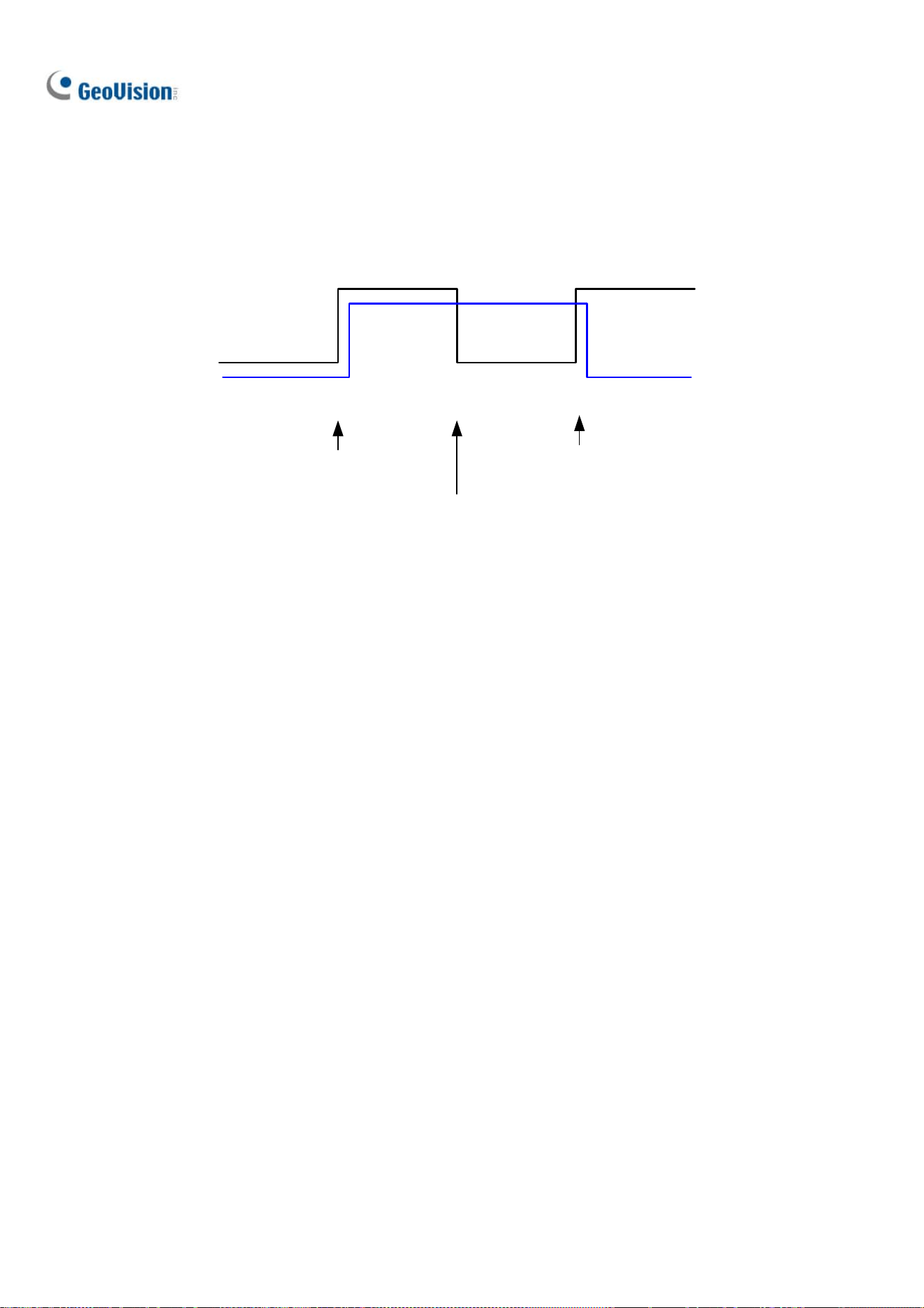
202
2. Input (N/O + Latch Trigger) + Output (N/O Toggle + Keep Last Toggle Status)
When “Latch Trigger” works with “Keep Last Toggle Status”, the output only has a momentary trigger
but also needs to remain ON even when you stop monitoring or restart the system. Therefore under
the two conditions, the output turns off when a new input triggers.
Input
Output
N/O N/O N/O
N/C N/C
N/C
1st Input Trigger 2nd Input Trigger
Stop monitoring /
Restart the system

I/O
Applications
203
6
6.1.5 Setting up PLC I/O devices
1. To connect a PLC I/O device to GV-VMS, click Home > Toolbar > Configure >
Accessories > PLC Device Setup. This window appears.
Figure 6-7
2. Click the Add button to type the name, IP Address, Port, Password, M-Pin Range and select
the
Connection Type of the PLC Device. The M-Pin Range supports up to 999999 pins
3. To bind the M-pins, click
Home > Toolbar > Configure > Accessories, and
select
I/O Device Setup, When the I/O Device Setup dialog box appears, select the PLC device,
click the
Add button and select PLC I/O.
Figure 6-8

204
4. In the PLC I/O Module Configuration Dialog, drag the pins on the left-hand side to the I/O module
on the right-hand side.
Note: Every Input/Output module can only support up to 16 pins. To use other pins, add more I/O
modules.
Figure 6-9

I/O
Applications
205
6
6.2 Advanced I/O Applications
After adding I/O devices to GV-VMS, you can configure advanced I/O applications, such as setting
alarm notifications, defining a PTZ camera movement upon input trigger, setting momentary or
maintained mode, and deactivating alarm and alert settings.
Click
Home > Toolbar > Configure > Accessories (if available) > I/O Device (if
available) >
I/O Application Setting. This dialog box appears.
Figure 6-10
Note: The Accessories option only appears when GV-Keyboard or GV-Joystick has been set up on
GV-VMS. The
I/O Device option only appears after at least one I/O device has been added.

206
6.2.1 Setting up Actions upon Input Trigger
You can set up the actions to take after the input device is triggered. Select an input on the left tand
clicking the Finger button
will apply the same settings to all inputs.
Figure 6-11
[Monitor Input]
Rec Video: Select to record one or multiple cameras upon input trigger. Specify the recording
duration and click the
Arrow button to select which camera to record upon input trigger. Use the
drop-down list to select whether to use the frame rate settings for Urgent Event or General Event.
For details on setting up Urgent and General Event, see
Configuring General Setting in Chapter 2.
Invoke Alarm: Select to activate computer alarm when the input is triggered. You can select the
alarm sound from the drop-down list.
Invoke to Send Alerts: Select to send e-mail notifications when the input is triggered. Click the
first Arrow button to select the associated camera channel for video to be sent. Click the second
Arrow
button to specify the recipient’s e-mail address. To attach video to the e-mail, it is required
to enable
Attach Image Setup in the email setup. See Setting up E-Mail Notifications in Chapter 1.
Output Module: Triggers the specified output module when the input is activated. Use the
drop-down lists to select the output module and pin number.
Register Input Event: Registers the I/O trigger events into System Log. Each event is labeled
with ID, time, device name (camera or I/O input), corresponding module of the device, and event
for later retrieval. For details on System Log
, see System Log in Chapter 1.
Tip: You can also select one output device to set up the Invoke to Send Alerts function for sending
e-mail notifications upon output trigger.

I/O
Applications
207
6
6.2.2 Moving PTZ Camera to Preset Points upon Input Trigger
This feature allows you to move the PTZ camera to preset points when an input is triggered. Select an
input number to be set up.
Figure 6-12
Preset Go by I/O: Enable the option and click the Arrow button to select your PTZ camera from
the drop-down list.
Alarm On: Moves the PTZ camera to a preset point when the input is triggered.
Alarm Off: Moves the PTZ camera to a preset point when the triggered input is off.
Preset Go by I/O - Alarm On Dwell Time: Specify the amount of time the PTZ camera stays at
“Alarm On” preset point, before returning to the “Alarm Off” preset point.
Note: Depending on the capability of the PTZ camera, up to 256 PTZ preset points (ranging from 1 to
256) and addresses (ranging from 0 to 255) can be programmed.

208
6.2.3 Setting up Momentary and Maintained Modes
Figure 6-13
[Momentary Mode] Push button switches that are normally open and stay closed as long as the
button is pressed. Momentary switches allow turn-on or turn-off from multiple locations.
For example, certain premises have a designated entry/exit door. When the staff enters the entry door,
the system starts monitoring. When the staff leaves from the exit door, the system stops monitoring.
[Maintained Mode]
Push-on/push off button switches that stay open until thrown, and then stay closed
until thrown again. Maintained switches are convenient for only one switch location.
For example, in the business hour when the door is opened, the system stops monitoring; in the
non-business hour when the door is closed, the system starts monitoring.

I/O
Applications
209
6
6.2.4 Deactivating Alarm and Alert upon Input Trigger
Figure 6-14
[Deactivate notification when selected pin is ON] When an assigned input module is activated, all
designated alarms and alerts will be disabled. Assign an installed input module and a pin number for
the application.
[Deactivate Notification] Click the Arrow button to select the alert to deactivate.
Triggered by: Select an alert condition from the drop-down list for the application. For example, if
you choose Motion, all designated alarms and alerts upon motion detection will be deactivated
when the assigned input module is activated.
Deactivate Selected Notification: Select the alarms and alerts you want to be deactivated, such
as Output, Wave Alarm and/or Send Alert, when the assigned input module is activated.

210
6.2.5 Other I/O Application Functions
In the I/O Device Application dialog box, you can also set up Input Overlay on live view, alert for I/O
errors, and whether to recycle input-triggered events. Select an Input number to be set up.
Figure 6-15
[Input Overlay]
Select to overlay the name of an input device on live video for alert or save the name
to video files upon the input trigger. Click the
Arrow button to select the camera to overlay input name.
To overlay the name of a triggered input on live video, click Home > Toolbar > Configure >
Video Process. In the dialog box that appears, select Text Overlay in the Video Analysis drop-down
list, select the camera, and click
Setting. Select Print on screen (Only for I/O alarm) and/or Print on
video file
. Up to 5 input names can be stamped on one camera channel when inputs are triggered.
[Never Recycling Input-Triggered Events] When selected, the files recorded upon input trigger won’t
be recycled by the system when disk space is full.
[IO Error Sound] When enabled, the computer alarm will sound when GV-VMS fails to detect the
connected I/O device.
[IO Error Alert] When enabled, an e-mail notification will be sent when GV-VMS fails to detect the
connected I/O device. For e-mail alerts, see
Setting up E-mail Notifications in Chapter 1.

I/O
Applications
211
6
6.3 I/O Devices in Content List
When an I/O device is added to the system, the I/O device will appear in the Content List.
1. To display the Content List, click
Home > Toolbar > Content List .
2. Click
I/O Device to see the I/O devices added to GV-VMS. When an input or output is triggered,
its icon will light up in the I/O Device list.
Figure 6-16
3. You can force the output device to be triggered by clicking its icon . Another way to trigger an
output is to select an output and click the
Force Output button .
4. To manually turn off a triggered output, right-click the triggered output in the list and click
Reset.

212
6.4 Visual Automation
The Visual Automation helps you automate any electronic device by triggering the connected output.
You can then intuitively click on the image of the electronic device, a light for example, to change its
current state, e.g. turning the light on.
1. On the main screen, click
Home > Toolbar > Configure > Accessories (if
available) >
I/O Device (if available) > Visual Automation Setting. This dialog box appears.
Figure 6-17
2. Select a camera from the drop-down list, and select Enable.
3. Drag a region on the camera view. A dialog box appears.
4. Select the connected module and output device. Type a
Note to help you identify the device.
5. To change the frame color of the set region, click the
Set Color button.
6. To test the output trigger, click the region on the camera view drawn in Step 3.
On the main screen, move the cursor to the camera view with the Visual Automation settings, click
Tools > I/O Automation. Next, click the region you set to trigger the connected output device.
You can right-click the camera view and select
Show all to see all Visual Automation regions if
needed.
Figure 6-18

213
Chapter 7
Remote Viewing..........................................214
7.1 Remote Viewing Using a Web Browser......................................215
7.2 WebCam Server Settings ................................................................218
7.2.1 General Settings ..........................................................................................218
7.2.2 Server Settings ............................................................................................. 219
7.2.3 Video Settings...............................................................................................220
7.2.4 Audio Settings...............................................................................................221
7.2.5 JPG Settings..................................................................................................222
7.2.6 UPnP Settings ...............................................................................................223
7.2.7 Network Port Information .........................................................................224
7.2.8 Mobile Service ..............................................................................................225
7.3 Single View Viewer ..........................................................................226
7.3.1 Adjusting Video Quality .............................................................................228
7.3.2 Control Panel.................................................................................................229
7.3.3 Configuring Single View Viewer Options............................................. 230
7.3.4 PTZ Control Panel........................................................................................ 233
7.3.5 Visual PTZ Control ......................................................................................234
7.3.6 I/O Control ......................................................................................................235
7.3.7 Visual Automation .......................................................................................236
7.3.8 Picture-in-Picture View..............................................................................237
7.3.9 Picture-and-Picture View ..........................................................................238
7.4 Multi-Window Viewer .......................................................................239
7.5 JPEG Image Viewer..........................................................................240
7.6 Playing Back Events.........................................................................241
7.6.1 Event List Query...........................................................................................241
7.6.2 Remote Playback .........................................................................................242
7.7 Remote ViewLog ...............................................................................243
7.8 Download Center ...............................................................................244
7.9 GV-Edge Recording Manager.........................................................245
7.10 Mobile Phone Applications ..........................................................246
7.11 Web Browsers on Smartphones .................................................246

214
Remote Viewing
With a Web browser, you can remotely view live video, download and play back video files, as well as
controlling PTZ cameras and I/O devices, through the WebCam Server.
The remote computer used to access live video must meet the following minimum requirements:
OS 64-bit Windows 7 / 8 / 8.1 / 10 / Server 2008 R2 /
Server 2012 R2 / Server 2016 / Server 2019
CPU 4
th
Generation i5-4670, 3.4 GHz
Memory 8 GB RAM
Hard Disk 80 GB
Network TCP/IP
Web Browser IE 7.0 or later
Chrome V38.0.2125.111 or later
Firefox 30.0 or later
Edge V20 or later
DirectX 9.0c
Note: Some remote functions may not be supported by non-IE browsers. However, users can
download the Web Viewer from non-IE browsers to access the full functions of the WebCam Server.
CHAPTER
7

Remote Viewing
215
7
7.1 Remote Viewing Using a Web Browser
GV-VMS has a built-in WebCam Server that allows you to remotely view and manage the camera
images from GV-VMS using a Web browser. Different browsers have slightly different user interfaces.
Note:
1. For Internet connection, GV-VMS must have an IP address or domain name from ISP. If the IP
address is dynamic, you may use the DDNS service to directly change IP addresses to
GV-VMS. For the service, see Dynamic DNS in Chapter 9.
2. Make sure the remote PC used to access GV-VMS meets the recommended system
requirements mentioned above.
3. If a router or firewall is installed with the GV-VMS system, ensure the following communication
ports required by the WebCam Server are open: Command Port (4550), Data Port (5550), Audio
Port (6550) and HTTP Port (80).
1. To enable the WebCam Server on GV-VMS, click Home
> Toolbar > Network >
WebCam Server. The Server Setup dialog box appears. You can click OK to close the dialog
box for now and modify the default configurations later.
2. On a remote computer, open a Web browser and type the IP address or domain name of
GV-VMS. The Webcam Login dialog box appears.
Note: If the default HTTP port 80 has been changed, type a colon and the port number after the IP
address, for example, Http://192.168.3.199:81/.
3. Type a user ID and password created on GV-VMS.

216
4. Click Login. When accessing the remote view for the first time, you may need to download and
install different files for different browsers:
a. For Internet Explorer, click the bar at the top of the browser and install plugin.
Figure 7-1
b. For Google Chrome, Microsoft Edge or Mozilla Firefox, download and run Web Viewer
from the left menu. After the connection to GV-VMS is established using the Web Viewer, you
can enjoy complete functions of the WebCam Server.
Figure 7-2

Remote Viewing
217
7
WebCam Server Features
Name Description
Live View
Accesses different types of live view viewers. See Single View Viewer,
Multi-Window Viewer and JPEG Image Viewer later in this chapter.
Remote Playback
Accesses remote playback options. See Playing Back Events later in this
chapter.
Remote ViewLog
Accesses the Remote ViewLog. See Remote ViewLog later in this chapter.
Remote eMap
Accesses E-Maps remotely set up at GV-VMS. See E-Map Application in
Chapter 8.
Download
Accesses the Download Center. This function offers optional viewing programs
to be downloaded to the local PC. See Download Center later in this chapter.

218
7.2 WebCam Server Settings
To enable and configure the built-in WebCam Sever, click Home > Toolbar > Network
> WebCam Server.
7.2.1 General Settings
Figure 7-3
Enhance network security: If enabled, a word verification step is required for each WebCam
Server’s login.
Enable AES: Select to add an additional security protection for live streaming between
GV-VMS and WebCam Server.
Enable Remote Control: Select to remotely configure the I/O devices through the WebCam
Server.
Run Viewlog Server: Select to remotely play back video files through the WebCam Server.
Run Bandwidth Control Server: Select to enable the Bandwidth Control Server. For details,
see Bandwidth Control Application in Chapter 9.
Run Mobile Service: Select to enable the mobile function to connect to GV-Eye and GV-Edge
Recording Manager (MAC Version).
Note: When Enhance network security is enabled, JPEG/Mobile applications will be disabled.

Remote Viewing
219
7
7.2.2 Server Settings
Figure 7-4
HTTP Port: Used to access the Internet. By default, it is 80.
Command Port: Used to access WebCam. By default, it is 4550.
Data Port: Used to transfer data over the Internet. By default, it is 5550.
Enable SSL: Enable the Secure Sockets Layer (SSL) protocol to ensure the security and privacy
of Internet connection. To use your own generated Certificate and Private Key or ones verified by
SSL authority, click the […] buttons and select the files stored at your computer. Note that the
system will enable both SSL 2.0 and SSL 3.0 as its default; to further enable TLS 1.0 protocol
when using SSL protocol, select Enable TLS 1.0.
Detect UPnP: For details, see UPnP Settings later in this chapter.
Note: If you want to enable SSL 3.0 on a computer running Windows Vista, it is required to upgrade
your system to Service Pack 1 or Service Pack 2.

220
7.2.3 Video Settings
Figure 7-5
Max. Channel(s): Specify the number of channels allowed to access the WebCam Server, with
the upper limit of 200 channels.
Max. Image size: Select a maximum resolution allowed for remote access. The default resolution
on the WebCam is Normal (320 x 240). The other options are Large (640 x 480 or 704 x 480) and
the Actual Size of that IP camera.
Allowed PTZ camera: Controls PTZ cameras at a remote computer. Click the button and select
the desired PTZ cameras to allow for remote access.
Note: To specify the time length allowed for a guest user to access the WebCam Server, click the
account ID at the top of the main page, click Password Setup, and select Local Account Edit. In the
WebCam tab, select the Limit Connection Time option and specify the time length. The time range is
between 10 and 3600 seconds.

Remote Viewing
221
7
7.2.4 Audio Settings
Connecting Audio Devices
Through the WebCam Server, you can access live audio at a remote site and talk to the server site
when necessary. Before using this feature, make sure all the necessary hardware are in place:
1. To record audio, check the connected IP camera has built-in audio function or an external
microphone connected.
2. Check your sound card is already inside the computer. Connect a multimedia speaker to the audio
output of your computer’s sound card for receiving audio from the remote site.
3. Connect a desktop microphone to the input of the audio extension card (or cable line) for sending
audio to the remote site.
Audio Setup
Figure 7-6
[Server to Client] Allows a remote computer to access live audio from GV-VMS.
Max. Channel(s): Enter the maximum number of channels allowed to access live audio, with the
upper limit of 40 channels.
[Client to Server] Allows a remote computer to speak to GV-VMS.
Max. Channel(s): Enter the maximum number of channels allowed to speak to the server site,
with the upper limit of 20 channels.
Port: The default audio port is 6550.
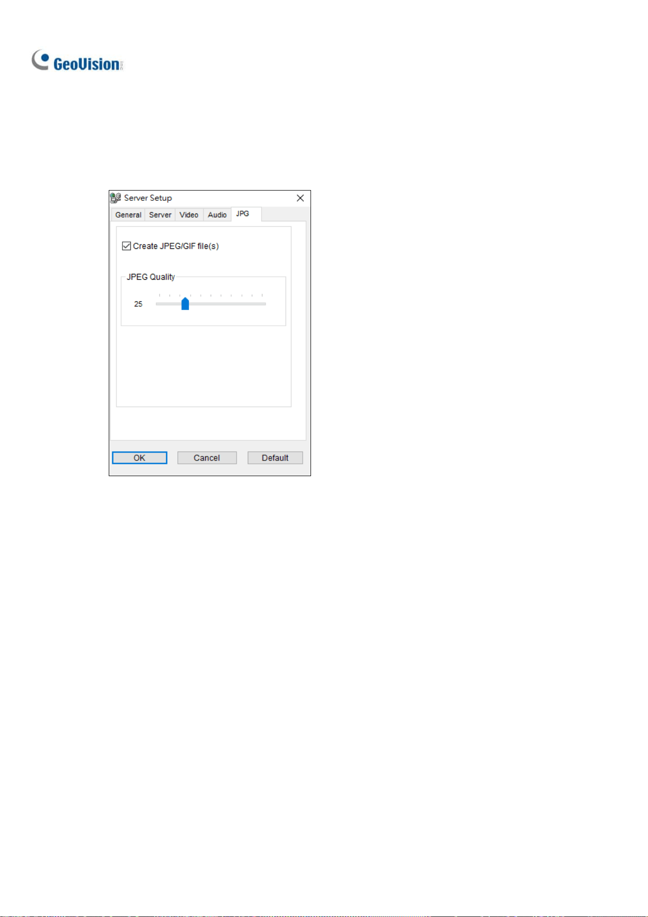
222
7.2.5 JPG Settings
These settings allow you to send JPEG or GIF files over the Internet.
Figure 7-7
Create JPEG/GIF file(s): You can access the JPEG images through the WebCam Server, and
adjust the image quality. Bigger number results in better image quality and bigger image file size.

Remote Viewing
223
7
7.2.6 UPnP Settings
The WebCam Server supports UPnP technology (Universal Plug and Play) to allow automatic port
configuration to your router. UPnP must be enabled both on your operating system and your router.
Enabling UPnP on the WebCam Server:
1. On the main screen, click Home
> Toolbar > Network > WebCam Server. The
Server Setup dialog box appears.
2. Click the Server tab and click Detect UPnP. This dialog box appears.
Figure 7-8
3. Click Searching to search the UPnP-enabled routers.
4. If your server is installed with multiple routers, select one from the UPnP Router drop-down list.
5. If you server is installed with multiple network adapters, select one from the drop-down list under
the Searching button.
6. Click Configure to automatically configure the communication ports on the router.
Note: If you don’t use the default ports, modify the related ports in the Server Setup dialog box
(Figure 7-4) and then click OK. Re-open the dialog box and follow the above steps to configure your
router.
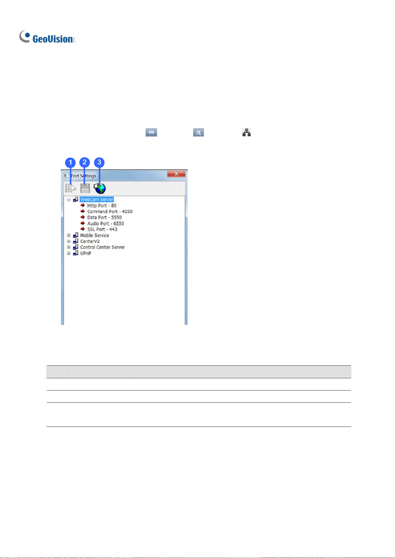
224
7.2.7 Network Port Information
The Network Port Information is designed for users to view and manage all network ports of remote
applications.
On the main screen, click Home
> Toolbar > Network > Network Port Information.
This dialog box appears.
Figure 7-9
The controls on the Port Settings:
No. Name Description
1 Modify Changes the port settings.
2 Save Saves the port settings.
3 Port Mapping
Employs UPnP technology (Universal Plug and Play) to allow automatic
port configuration to the router.

Remote Viewing
225
7
7.2.8 Mobile Service
Mobile Service allows remote connection and video streaming from GV-VMS by other applications,
namely GV-Eye, GV-Edge Recording Manager – Mac version and the multicast of GV-Control Center.
You can also add additional security protection for live streaming between GV-VMS and the connected
application using AES Encryption.
For details on configuring multicast on GV-Control Center, see Multicast Setting, Chapter 9, in
GV-Control Center User’s Manual.
To add AES Encryption:
1. After connecting to GV-Edge Recording Manager / GV-Control Center / GV-Eye, on the main
screen of GV-VMS, click Home
> Toolbar > Network > Mobile Service.
2. Select Enable AES Encryption.
Figure 7-10
Note: The AES Encryption function is only compatible with
GV-Edge Recording Manager V1.3.0.0 or later
GV-Control Center V3.5.0.0 or later
GV-Eye V2.5 or later
GV-VMS (WebCam Server) V17.1 or later

226
7.3 Single View Viewer
After logging into the WebCam Server successfully, you can see the single live view from GV-VMS.
2
6
8
9
10
3
4
5
11
12
1314
7
1
Figure 7-11
The controls in the Single View Viewer:
No. Name Description
1 Live Video
Right-clicking on live view allows you to instantly access some useful
functions. The Resolution option can display a resolution indicator at the
bottom right corner of the video.
2 Control Panel
See Control Panel later in this chapter.
3 Options
See Alarm Notification, Video and Audio Configuration, Server List,
Show Camera Name and Image Enhancement later in this chapter.
4 Change Camera Selects the desired camera for display.
5 PTZ Control
See PTZ Control and Visual PTZ Control Panel later in this chapter.
6 I/O Control
See I/O Control later in this chapter.
7 Full Screen
Switches to full screen view. The maximum video resolution configured
on the WebCam Server will be applied. See Video Settings in WebCam
Server Settings earlier in this chapter.
8 File Save Saves video to a local computer in AVI format.

Remote Viewing
227
7
9 Change Quality
See Adjusting Video Quality later in this chapter.
10 Snapshot Takes a snapshot of the displayed live view.
11 Speaker
See Video and Audio Configuration later in this chapter.
12 Microphone
See Video and Audio Configuration later in this chapter.
13 Stop Terminates the connection to the remote GV-VMS.
14 Play Connects to the remote GV-VMS.
Displaying Full-Screen Live View on Other Monitors
Using the IE browser, you can display up to 10 full-screen channels with multiple monitors installed.
Right-click the live view and select a designated monitor to bring full-screen live view. The full-screen
live view appears on the designated monitor immediately.
Note: The full-screen display closes at the designed monitor if its Web interface window is
minimized.

228
7.3.1 Adjusting Video Quality
To adjust the live view quality to have megapixel resolution in the Single View Viewer:
1. Select Actual Size on GV-VMS. Click Home
> Toolbar > Network > WebCam
Server > the Video tab > select Actual Size in the Max. Image Size option.
Figure 7-12
2. On the Single View, click the Change Quality button (No. 9, Figure 7-11). You will have the
option of megapixel resolution now.
Note:
1. Streaming live view in Actual Size requires a lot of bandwidth. It is highly recommended to enable
this function in a LAN environment.
2. To have fisheye dewarping view, you must first follow the steps above to set fisheye camera to
megapixel resolution. Next, right-click the camera view and select Geo Fisheye. For details on the
fisheye settings, see Fisheye View in chapter 3.

Remote Viewing
229
7
7.3.2 Control Panel
A control panel can be opened next to the live view by clicking the Menu button and selecting any of
the options. To change the pages of the control panel, use the right and left arrow buttons on the panel,
or click the Menu button to directly make selection.
Figure 7-13
Name Description
Information
Displays the current version, local time, host time and number of channels
currently accessing WebCam.
Video Displays the current video codec, resolution and data rate.
Audio
Displays audio data rates when the microphone and speaker devices are
enabled.
Preset Go Allows you to remotely move the PTZ to the preset points.
I/O Control Provides a graphic display of the input and output devices from GV-VMS.
Alarm Notify
Displays the captured images by sensor triggers and/or motion detection.
See Alarm Notification later.
Camera Adjustment Remotely adjusts image quality by moving the slider to the desired values.
POS/Wiegand Not functional.
People Count
Views the counts of Object Counting along with live view. Once the counts are
logged into GV-VMS, In and Out counts will become zero and the system will
start counting those numbers again.

230
7.3.3 Configuring Single View Viewer Options
To access the Single View Viewer options, click the Option button located on the right of the live view.
Figure 7-14
Alarm Notification
Up to four captured images can be shown in the control panel upon motion detection or input trigger.
Figure 7-15
1. Click the Option button, and select Alarm Notify. The Alarm Notify dialog box appears.
Motion Notify: The captured images are displayed in the control panel of the Single View
upon motion detection.
I/O Alarm Notify: The captured images are displayed in the control panel of the Single View
upon input-triggered detection.

Remote Viewing
231
7
Alert Sound: Activates the computer noise alarm on motion and input-triggered detection.
Auto Snapshot: The program will take a snapshot every 5 seconds on motion and
input-triggered detection.
File Path: Assigns a path to save the snapshots.
2. Click OK to apply the above settings.
Video and Audio Configuration
To change the video and audio configurations of the connected camera, click the Option button, and
select Video and Audio Configuration.
Figure 7-16
[Camera] Change the video codec, quality and frame rate. The resolution options depend on the
maximum image size set on the connected GV-VMS. For details, see Video Settings in WebCam
Server Settings earlier in this chapter.
[Audio Configure] Enable the microphone and speaker for two-way audio communication. Select
Speaker to access live audio from the server site, and select Microphone to speak to the server site.
Ensure the speaker and microphone are properly installed in the local computer, and the audio settings
(Figure 7-6) are activated on the WebCam Server too. There are three options for audio quality:
Real Time: Transmits simultaneously audio and video but may create sound interruption,
depending on your network condition.
Smooth: Has a smooth sound quality but without audio and video synchronization.
Normal: The default value which has the audio and video effects between Real-Time and Smooth.
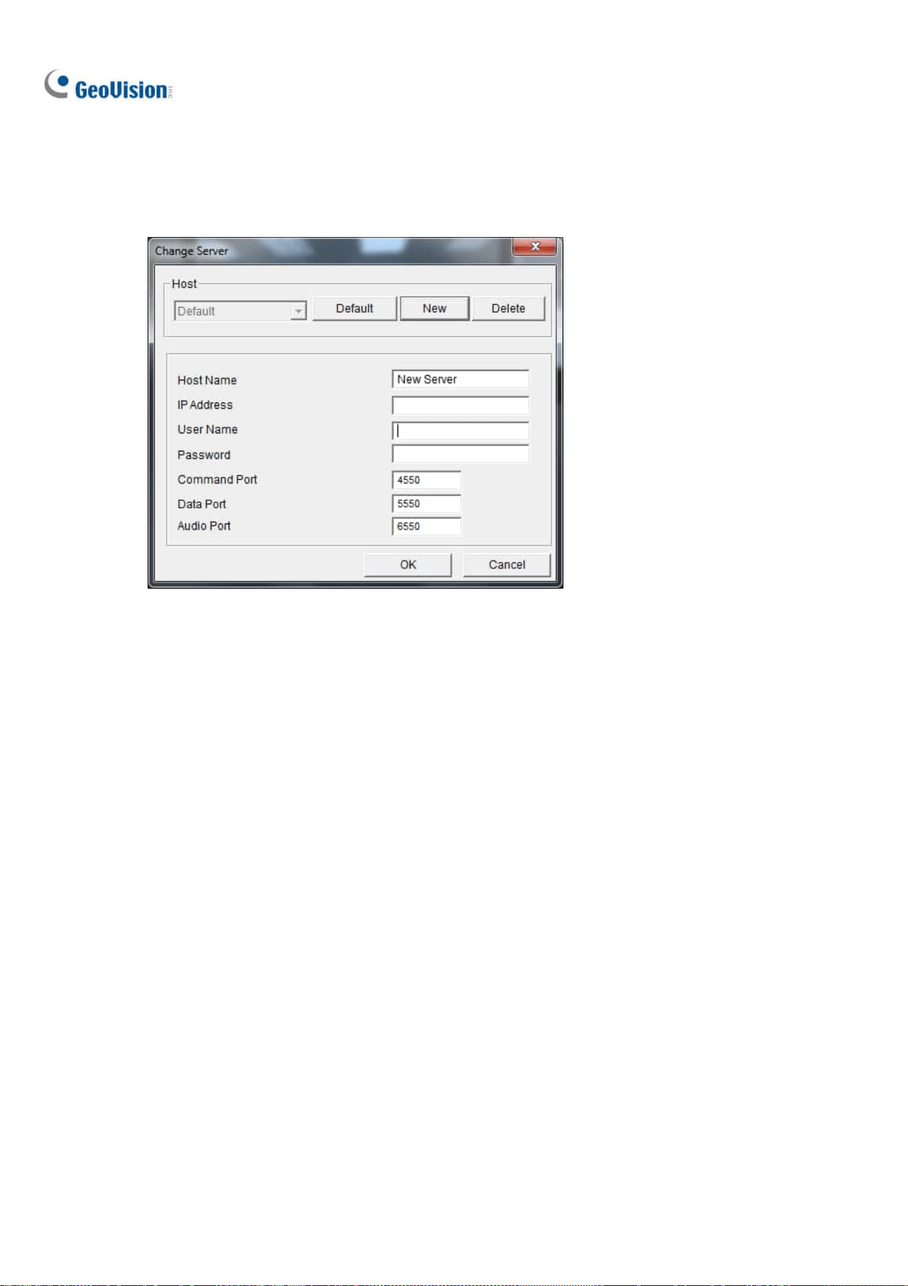
232
Server List
You can add the connection information of multiple GV-VMS systems to the WebCam Server for quick
access later. Click the Option button > Change Server to display the following dialog box.
Figure 7-17
To add a GV-VMS system to the drop-down list, click the New button and type its connection
information. Leave all port settings as defaults at 4550, 5550, and 6550 respectively unless otherwise
necessary. Click the OK button. Then the created GV-VMS will appear in the Host drop-down list.
Show Camera Name
To show camera name on top-left corner of the live view, click the Option button and select Show
Camera Name.
Image Enhancement
To enhance the image quality of live view, click the Option button and select Image Enhance.
De-Interlace: Converts the interlaced video into non-interlaced video.
De-Block: Removes the block-like artifacts from low-quality and highly compressed video.
Enable DirectDraw: Enabled by default to enhance image quality. Some graphics cards might
not support DirectDraw and can produce distorted frames. In this case, disable the DirectDraw
function.
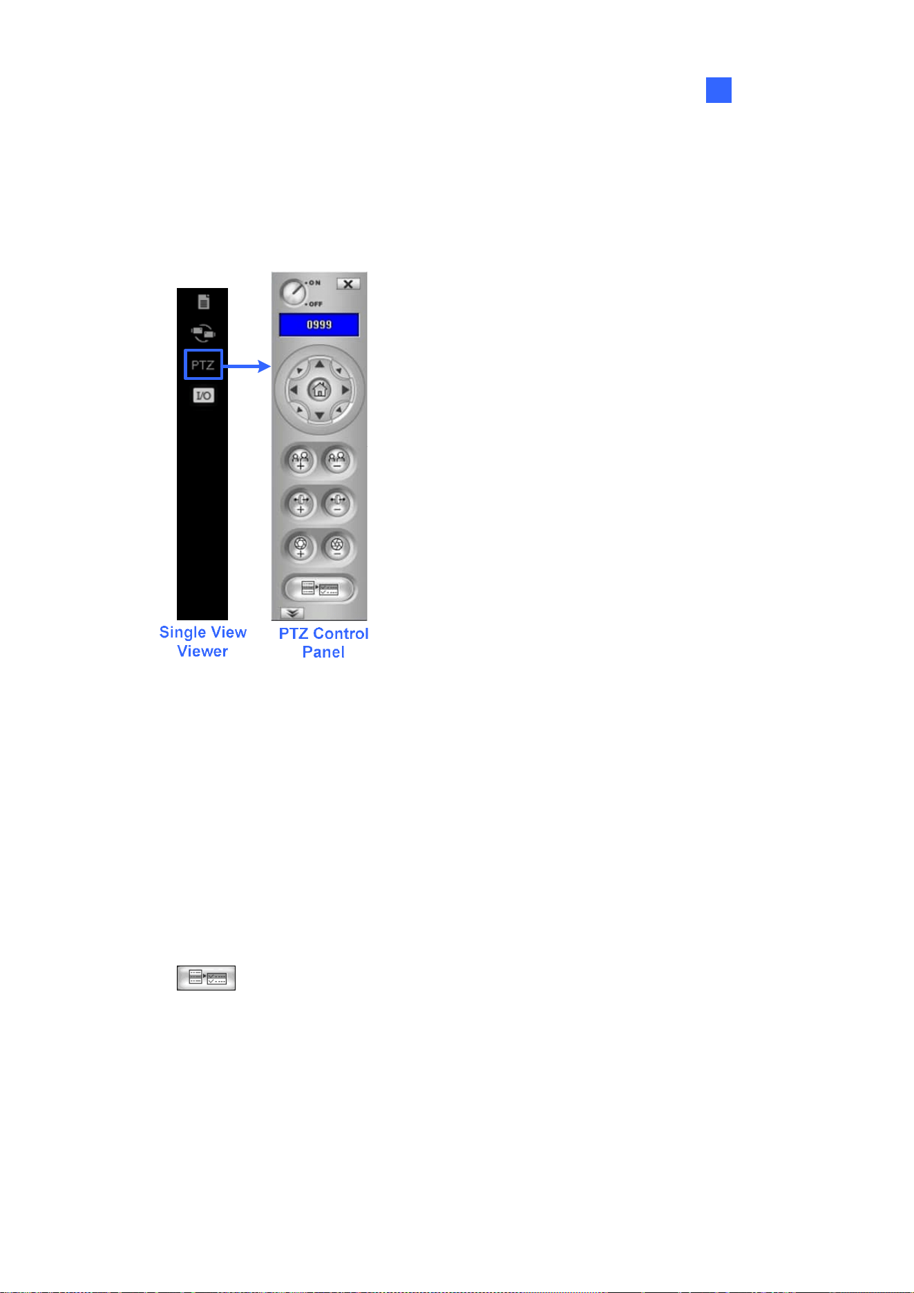
Remote Viewing
233
7
7.3.4 PTZ Control Panel
Click the Camera Select button to select one PTZ camera, and click the PTZ Control button (No. 7,
Figure 7-14) to bring up the PTZ control panel.
Figure 7-18
One PTZ camera can only be controlled by one user at a time. If several users are trying to control the
same PTZ camera at the same time, the Single View viewer will give the priority to the first logon user
and then to the next user in queue.
Each user will be given 60 seconds to control the PTZ camera. The Timer at the upper right corner
informs the user of the remaining time of control or the total waiting time. The supervisor is given 666
seconds, which the highest priority to control the PTZ camera.
Click the
button to access additional PTZ functions. The functions available vary, depending
on the PTZ models.

234
7.3.5 Visual PTZ Control
Other than the PTZ control panel, you can enable the Visual PTZ Control functions. Right-click the live
view and select Visual PTZ. Next, click the green PTZ button on the top left corner of the PTZ control
window to have these options:
Random Move: You can move the camera view to any direction by clicking on a desired direction.
When you place the mouse cursor on the live view, a circular PTZ control panel appears. See PTZ
Control Panel and Auto Functions in Chapter 1 for details on the circular PTZ control panel.
Figure 7-19
Center Move: Only for GV-SD220, you can zoom in and out using the mouse scroll or by drawing
a block directly on the live view.

Remote Viewing
235
7
7.3.6 I/O Control
The I/O control panel shows the I/O status and alarm event. Additionally, you can force output, as well
as enable and disable I/O devices to the remote GV-VMS. Click the I/O Control button at the right of
the live view to bring out the I/O control panel.
I/O Control Panel
Single
View
Viewer
Figure 7-20
The alarm status shows the triggered inputs. Clicking the Reset button will clear the alarm list.
To force to trigger an output device, click the Enable button, highlight an output and then click the
Output button. The Timer functions the same as in the PTZ control panel. Each user will be given 60
seconds of control time while the supervisor has 999 seconds. Clicking the Stop button will stop the
operation and turn over the control privilege to the next user waiting online.
If you want to enable or disable I/O devices connected to the remote GV-VMS, click the
Enable/Disable I/O button. Note that the Enable Remote Control option must be enabled beforehand
in the WebCam Server Setup dialog box (Figure 7-3)

236
7.3.7 Visual Automation
If the Visual Automation function is enabled on GV-VMS, you can remotely trigger the connected
output by simply clicking on a designated spot on the live view. For details on setting up Visual
Automation, see Visual Automation in Chapter 6.
1. To access this feature, right-click the live view and select Visual Automation. A green I/O icon
appears in the corner.
2. To see where the designated visual automation spots are located, right-click the live view again,
select Visual Automation and select Show All.
3. Click the alert areas on the image to force the outputs to be triggered remotely.
Figure 7-2

Remote Viewing
237
7
7.3.8 Picture-in-Picture View
With the Picture in Picture (PIP) view, you can crop the video to get a close-up view or zoom in on the
video. This function is useful in providing clear and detailed images of the surveillance area.
1. Right-click on the screen and select PIP. An inset window of the camera view appears in the live
view.
Figure 7-22
2. Move the navigation box around in the inset window to have a close-up view of the selected area.
You can adjust the size of the navigation box if needed.
3. Drag the inset window to adjust its location on the live view if needed.
4. To exit the PIP view, click the camera name and click PIP View again.

238
7.3.9 Picture-and-Picture View
With the Picture and Picture (PAP) view, you can create a split video effect with multiple close-up views
on the image. A total of 7 close-up views can be defined. This function is useful for megapixel
resolution that provides clear and detailed images of the surveillance area.
1. Right-click on the live view and select PAP. A row of three inset windows appears on the bottom of
the screen.
2. Draw a navigation box on the image, and this selected area is displayed in one inset window. Up to
seven navigation boxes can be drawn on the image. You can adjust the size and the location of the
navigation box if needed.
Figure 7-23
3. To exit the PAP view, right-click the live view and select PAP again.
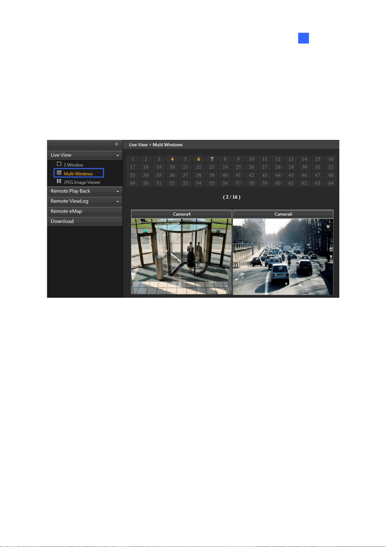
Remote Viewing
239
7
7.4 Multi-Window Viewer
The Multi Windows displays up to 16 channels at a time and supports up to 64 channels.
To access the Multi Windows, click Live View on the left panel of the Webcam Viewer page, and select
Multi Windows.
Figure 7-24

240
7.5 JPEG Image Viewer
JPEG Image Viewer is a cross-platform viewer, compatible with Mac OS and Microsoft IE browsers.
Continuously receiving JPEG images from GV-VMS and limited to a single camera view, the viewer is
an ideal tool for the users with limited Internet bandwidth.
Note: To enable the JPEG Image Viewer, Java needs to be installed on the local PC.
To enable the viewer:
1. Click Home
>Toolbar > Network > WebCam Server.
2. Disable Enhance Network Security under the General tab (Figure 7-3), and enable Create
JPEG/GIF File(s) under the JPG tab (Figure 7-7).
3. Access GV-VMS using a Web browser.
4. On the left panel of Singe View page, click Live View and select JPEG Image Viewer. The JPEG
Image Viewer appears.
Figure 7-25

Remote Viewing
241
7
7.6 Playing Back Events
7.6.1 Event List Query
The Event List Query function on the WebCam Server allows you to remotely search for an event by
defining event type and time. The search results can be displayed in text form or in a chart. You can
also play back events instantly from the search results.
To allow remote access to GV-VMS and remotely play back events,
Ensure the WebCam Server with the Run ViewLog Server function (Figure 7-3) is activated on
GV-VMS.
1. On the left panel of the Single View page, click Remote Play Back and select Event List Query.
The Query window appears.
2. On the top, select one of the following search categories: Monitor, System, Login, Counter,
Merge, Backup and Delete. Note that these categories are based on those of System Log in the
Main System.
3. Define the search criteria such as Event Type, Device, Information, Date and etc. The selection of
search criteria may vary, depending on search categories.

242
4. Click Submit Query. The search results are displayed.
Figure 7-26
5. To play back the attached video, click the Video icon. For more playback features, right-click on
the video image.
6. To graph the search results, click the Chart button.
7. To export the search results, select one of the formats and click the Export button.
7.6.2 Remote Playback
With the Remote Playback (RPB) function on the WebCam Server, you can play back the recorded
files of the connected GV-VMS.
1. To allow remote access to GV-VMS, ensure the WebCam Server with the Run ViewLog Server
function (Figure 7-3) is activated on GV-VMS.
2. On the left panel of the Single View page, click Remote Play Back and select Remote Play Back.
The Remote Play Back appears.
3. Select the desired camera, date and time-segment file.
4. Click the Play button to start.
5. For additional playback features, right-click on the image to have the options of Play Mode,
Render and Tools.

Remote Viewing
243
7
7.7 Remote ViewLog
Through the WebCam Server, you can remotely play back the recorded files by using the ViewLog player.
1. To allow remote access to GV-VMS, ensure the WebCam Server with the Run ViewLog Server
function (Figure 7-3) is activated on GV-VMS.
2. On the left panel of the Single View page, click Remote ViewLog. Remote ViewLog will be
installed on your PC if it is not already.
Figure 7-27
3. Execute GV-Remote ViewLog and create a Remote ViewLog account on the Add Remote Viewlog
Account dialog box.
4. After creating an account, the Add New Host dialog box appears.
5. In the Host Type, select DVR / NVR / VMS. Type the Location Name, IP Address, Account and
Password of GV-VMS. Only modify the default port 5552 if necessary.
6. Click OK. The events available will be listed in the Event List.
For details on ViewLog player functions, see Chapter 4.
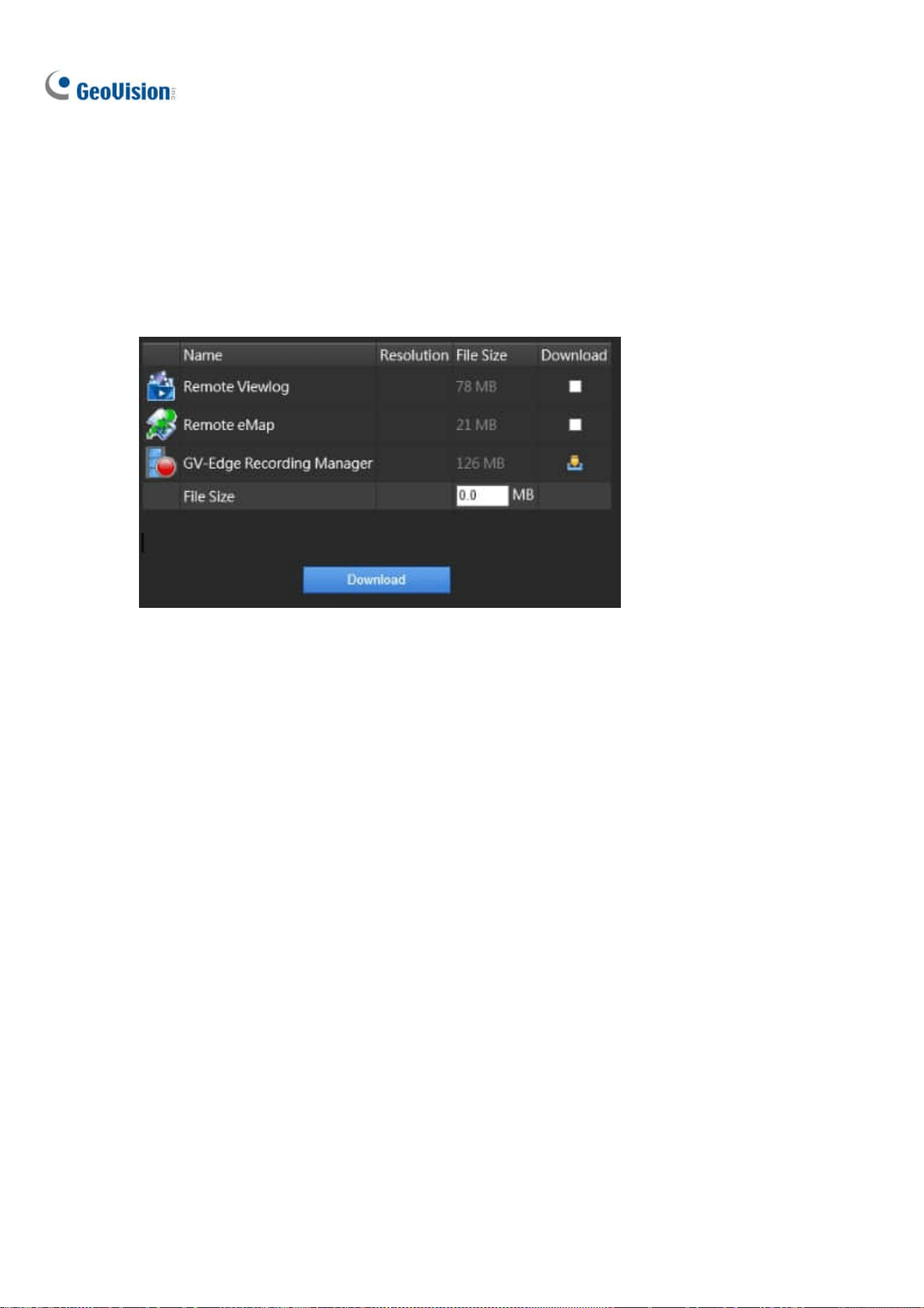
244
7.8 Download Center
The Download Center allows you to download Remote ViewLog, Remote eMap and GV-Edge
Recording Manager.
1. Click Download in the left panel of the Single View page. This page appears.
Figure 7-28
2. Check the desired programs. The File Size field will display the total file size of the selected
programs.
3. Click Download and follow the on-screen instructions to install the programs. When the installation
is complete, the message “Install Complete” will be displayed.

Remote Viewing
245
7
7.9 GV-Edge Recording Manager
GV-Edge Recording Manger is designed for remote live viewing and playback of GeoVision IP devices
and software. GV-Edge Recording Manger brings live view and allows remote control of GV-IP Camera,
GV-Video Server and GV-SNVR, as well as GV-DVR / NVR / VMS and GV-Recording Server, together
under one management interface.
For details on GV-Edge Recording Manager, visit our website:
GV-Edge Recording Manager (Windows Version)
GV-Edge Recording Manager (MAC Version)
GV-Edge Recording Manager (Windows Version): Make sure that Control Center Service and
Remote ViewLog Service are enabled on GV-VMS.
GV-Edge Recording Manager (MAC Version): Make sure that Webcam Server and Mobile
Service are enabled on GV-VMS.
Win version MAC version
Figure 7-29
Note:
1. Mobile Service has the same function as Run Mobile Service (WebCam Server > General
Tab).
2. To add additional security protection of the live streaming between GV-VMS and GV-Edge
Recording Manager through AES encryption, see Mobile Service earlier in this chapter.

246
7.10 Mobile Phone Applications
With a smartphone, you can access live view and play back recordings from GV-VMS using GV-Eye
mobile app. GV-Eye can be downloaded from App Store or Android Market.
For details, see GV-Eye Installation Guide
7.11 Web Browsers on Smartphones
Using the browser on your smartphone, you can watch live view, control PTZ live views, and play back
recordings from GV-VMS. By connecting to the WebCam Server, no extra application is required.
Note:
1. Make sure the Mobile Service is enabled on the WebCam Server.
2. Live view control is only available for supported PTZ cameras.
In the following steps, we use the Android smartphone as an example to log onto GV-VMS:
1. Open the browser on your Android device and type the IP address of GV-VMS to log on.
Figure 7-30

Remote Viewing
247
7
2. Click Login. The cameras on GV-VMS appear.
Figure 7-31
3. To watch live view, keep H.264 as Streaming Type, and tap a video icon
. Stream 1 will be
displayed when Best Quality is selected and Stream 2 will be displayed when Low Quality is
selected.
4. To access the PTZ functions, tap JPEG as Streaming Type. This page appears. You can control
the live view with the direction arrows, zoom in/out and home position buttons.
Figure 7-32

248
Chapter 8
E-Map Application.......................................249
8.1 The E-Map Editor.............................................................................. 249
8.1.1 The E-Map Editor Window ........................................................................ 250
8.1.2 Creating an E-Map .......................................................................................251
8.1.3 Creating an E-Map for a Remote Host.................................................. 254
8.2 Starting E-Map .................................................................................. 255
8.2.1 Setting up the Popup Map ........................................................................256
8.3 3D E-Map Display ............................................................................. 257
8.3.1 3D E-Map Display .........................................................................................257
8.3.2 Utilizing the 3D E-Map Icons ...................................................................258
8.4 Remotely Accessing E-Map .......................................................... 259
8.4.1 The Remote E-Map Window ..................................................................... 260
8.4.2 Accessing E-Maps of Multiple Hosts ....................................................261
8.4.3 Configuring the Remote E-Map ...............................................................262
8.4.4 Viewing Event List and Playing Back Videos ....................................264
8.5 E-Map Server ..................................................................................... 264
8.5.1 Installing E-Map Server .............................................................................264
8.5.2 The E-Map Server Window ....................................................................... 265
8.5.3 Setting up E-Map Server ...........................................................................266
8.5.4 Connecting to E-Map Server....................................................................266

249
E-Map Application
The E-Map displays the monitoring area on an electronic map, by which the operator can easily locate
the cameras, sensors and alarms triggered by motion or I/O devices.
The application is available through two programs: E-Map Editor which comes with the installation of
GV-VMS, and E-Map Server applicable on a designed server.
8.1 The E-Map Editor
The E-Map Editor allows you to import a floor plan in BMP, GIF or JPEG formats, and use the icons of
cameras and I/O devices to customize a map.
CHAPTER
8

250
8.1.1 The E-Map Editor Window
The E-Map Editor comes with the installation of GV-VMS. Click the Windows Start menu, find
Programs, select GV folder and click E-Map Editor. The E-Map Editor window appears.
Figure 8-1
The controls in the E-Map Editor window:
No. Name Description
1 Up Returns to the previous E-Map file.
2 Add Map Adds an E-Map file.
3 Add Host Adds a host folder in the Host View.
4 Load Map Imports a floor map.
5 Rename Renames an E-Map file and/or folder.
6 Delete Deletes an E-Map file and/or folder.

E-Map Application
251
8
No. Name Description
7 & 8 Zoom In / Out Enlarges / Diminishes the Map View.
9 Fit to Screen Adjusts the Map View to fit the current size of the window.
10 Actual Size Displays the actual size of the imported graphic file.
11 Floor Plan The view of imported graphic file.
12 Map View Tree view of E-Map files.
13 Host View Tree view of hosts
8.1.2 Creating E-Map
1. To create an E-Map, click Add Map on the toolbar. A New Map file is created in Map View
and the Floor Plan window separately.
Figure 8-2
2. Click the New Map file in Map View, and click the Load Map button (No. 4, Figure 8-1) to import a
graphic file. The file opens in the Floor Plan window.
3. Drag and drop the icons from Host View (No. 13, Figure 8-1) onto the map in the Floor Plan
window.
4. To change the orientation of the default camera icon, right-click the camera from the Host View,
and select an orientation.
5. To change the camera / IO icon to your own, right-click the camera / IO from the Host View, and
add your own icon.
Note: Make sure the icon file is of 32 x 32 pixels or smaller.

252
Define the condition that the icon appears by selecting No Event or Event and select the
icon orientation using the drop-down list. You can set different icons for an event and
no-event situation. In this example, the icon of IPCam.jpg appears on the map when no
event occurs and when an event occurs, the icon changes to the default one.
Figure 8-3
6. Click File in the window menu and select Save to AI Guard to save the file to the GV-AI Guard
folder, or select Save to File to save the file to a desired path.
Advanced Settings
Optionally, you can have the following settings on your created E-Map.
Note: The changes in the orientation of camera icons will not be reflected on the 3D E-Map.
A. View Zone
The View Zone function illustrates the monitored area of each camera on the E-Map.
1. In the E-Map Editor window, click to highlight a camera icon, and select Edit View Zone. A
fan-shaped view zone appears.
Figure 8-4
2. Move the mouse to adjust the size and direction of the view zone.

E-Map Application
253
8
3. Right-click the map and select Finish to finalize the zone.
4. You can also adjust the property of the view zone from the Property menu.
Figure 8-5
B. Polygonal Map
The Polygonal Map function helps you quickly locate a triggered device. Draw an area on the map and
it will flash when any device within the area is triggered.
1. In the E-Map Editor window, click to highlight a map, and select Edit Polygonal Map or Edit
Polygonal IO.
2. Click on the map to start drawing a polygonal shape, indicated by a yellow dotted line.
Figure 8-6
3. After closing the shape, right-click the map and select Finish.
The enclosed area will be colored in blue. When a device placed within the polygonal map is triggered,
the blue area will flash in blue and red.
The enclosed area is colored in blue. When any device within the area is triggered, it will flash red.

254
8.1.3 Creating E-Map for a Remote Host
Aside from for the local host (GV-VMS), E-Maps can also be created for remote host(s). Through the
Remote E-Map function, these E-Maps can be accessed and monitored through a Web browser. For
how to remotely access E-Maps, see Accessing E-Maps of Multiple Hosts later in this chapter.
Note: The supported hosts for E-Map include GV-DVR / NVR / VMS, GV-IP Devices, GV-Video Server
and GV-Compact DVR.
1. Click Add Host
on the toolbar and select the type of host. A new host is added in Host View.
2. Right-click the created host and select Host Settings. This dialog box appears, which varies
depending on the host.
Figure 8-9
3. Type the necessary information, such as IP address and the number of cameras, and click OK.
4. Follow the instructions in Creating an E-Map earlier in this chapter to create an E-Map for the
remote host.

E-Map Application
255
8
8.2 Starting E-Map
After an E-Map is created, you can start the E-Map on GV-VMS and monitor through the E-Map. When
any camera and/or I/O device on it is triggered, the corresponding icon will blink as an alert.
1. On the Content List of GV-VMS, expand the E-Map folder and drag the created E-Map to the live
view grid. The E-Map is displayed.
Figure 8-10
2. When any camera or I/O device on the E-Map is triggered, its corresponding icon will blink red.
Hover the cursor over the icon to see a live image of the event or click the icon to see the full view.
Figure 8-11
Note: If you have created the E-Maps for multiple hosts, you can also see these map files in the
Content List. However, these map files won’t function on GV-VMS but only work on Remote WebCam
through a Web browser. See Accessing E-Maps of Multiple Hosts later in this chapter.

256
8.2.1 Setting up Popup Map
When multiple E-Maps are being monitored simultaneously, the popup function can be enabled for
monitoring convenience. Once any camera or I/O device is triggered, its corresponding E-Map will pop
up, replacing the current E-Map.
1. In the Content List, click the Configure button under E-Map.
Figure 8-12
2. Select the desired cameras and input devices for the application, and specify Interrupt Interval
for the duration between event triggers. Any event trigger will be ignored by the system during the
interval to avoid frequent map popup.
3. At the bottom of the E-Map grid, click E-Map Auto Pop-up
to enable the function.
Figure 8-13

E-Map Application
257
8
8.3 3D E-Map Display
Note the 3D E-Map function are only applicable to GV-VMS V16.10.3.0 or later.
8.3.1 3D E-Map Display
The E-Map can display the monitoring area in 3D view, meaning you can zoom in and out with the
mouse wheel, and rotate the view as you wish.
1. Create an E-Map by following the instructions in Creating an E-Map earlier in this chapter. To build
multiple layers of maps, create another subfolder under the E-Map folder, as illustrated below.
Figure 8-14
2. After creating an E-Map, click Home > Toolbar > Content List on GV-VMS.
3. Expand the E-Map folder and drag the created E-Map to the live view grid
4. To zoom in / out of the monitoring area, simply scroll the mouse wheel up or down.
5. To adjust the angle of view, click and hold on the E-Map and move in any direction as desired.
6. To move up or down the building view (No 2, Figure 8-15), right-click on the E-Map and scroll the
wheel.

258
8.3.2 Utilizing 3D E-Map Icons
The 3D E-Map display comes with a set of icons for settings and control. Place the mouse cursor on the
E-Map to see the icons below.
Figure 8-15
No Icons Functions
1 Move Up Move to the main folder of the current E-Map.
2
Building View
Switch the floor plan to 3D view mode of the building.
3 Map List Display the E-Map list.
4 E-Map Auto Popup Enable this function to automatically pop up the related map whenever
any device on it is triggered. See Setting up Popup Map earlier in this
chapter.
E-Map Application
259
8
5
Tools
Includes the following options:
Auto Rotate: Automatically rotates the E-Map anticlockwise.
Icon Options:
Always Show Live Video: When selected, the
received camera live view will always be displayed on
the E-Map.
Show Device Name: Display the device name on the
E-Map. This option is enabled by default.
Large Icons: Change to large icons of cameras. By
default, the large icons are used.
Small Icons: Enable this option if you want to use
small icons.
Properties: Show the E-Map name on the upper-left corner
and change the font size of the E-Map name.
Close: Remove the E-Map display.
8.4 Remotely Accessing E-Map
You can remotely access and view E-Maps with a Web browser.
1. To remotely access E-Maps through a Web browser, click Home
> Toolbar > Network
> WebCam Server on GV-VMS. The Server Setup dialog box appears.
2. Click OK to start the WebCam Server.
3. Open the Web browser and type the address of GV-VMS. Once the connection is established, the
Single View page appears.
4. On the left panel, click Remote E-Map. The Login dialog box appears.
5. Type the login info of GV-VMS and click
. The Remote E-Map window is displayed.

260
8.4.1 The Remote E-Map Window
Figure 8-16
The controls in the window:
No. Name Description
1 Login Logs up to 500 hosts.
2
Host
Information
Views the information of incoming events upon motion detected and I/O devices
triggered.
3 Previous Goes to the last selected E-Map file.
4 Home Goes back to the top of the tree view.
5 Next Goes to the next E-Map file.
6 ViewLog
Accesses the Remote ViewLog function. For details, see Remote ViewLog
Service in Chapter 4.
7 Configure Configures the advanced settings.
8 Tree List Displays all created E-Map files and folders.
9 IP Address
Displays the IP Address of the connected host.
10
Camera / Input /
Output Icon
When events occur, the corresponding icons will blink red.
Camera icon: Move the cursor over the icon to view a live image. Click the icon
to open a control panel for the camera.
Output Icon: Click the icon to manually trigger the output device. .

E-Map Application
261
8
Note: By default, E-Maps opened with Remote E-Map are displayed in 3D. To display the E-Maps in
2D view, click the Configure button (No. 7, Figure 8-16) and select Disable 3D eMap.
The controls in the Camera Icon
Figure 8-17
8.4.2 Accessing E-Maps of Multiple Hosts
If you have created E-Maps for multiple hosts, you can monitor these E-Maps remotely through a Web
browser. Up to 500 hosts can be accessed at a time.
1. To start, click Login
on the Remote E-Map window. The Login window appears.

262
2. Select a host on the right panel and click Login. You are prompted for the required login info.
Figure 8-18
3. Click OK to return to the Remote E-Map window. Now you can select the corresponding E-Map for
the new host for monitoring.
8.4.3 Configuring the Remote E-Map
Click Configure on the Remote E-Map window. The Configure window appears.
Figure 8-19

E-Map Application
263
8
[Download E-Map files] Download E-Map files from the local server to the client PC. This option can
reduce network loading if you wish to view the E-Maps of multiple hosts.
Use local E-Map files: After downloading E-Map files to the client PC, you can select and use
these E-Map files for connection.
[Motion] / [I/O Input]
Alert Sound: Assign a .wav file to alert the operator when cameras or I/O devices are triggered.
Camera Blink, I/O Blink: When cameras or I/O devices are triggered, their icons on the E-Map
flash. Deselect this option to stop the icons from blinking.
E-Map Auto Popup: When cameras or I/O devices are triggered, the related map will pop up on
the screen instantly when the Remote-E-Map window is minimized.
Show Event: Display motion or I/O triggered events on the Host Information window.
I/O Trigger Camera: When input devices are triggered, the related camera views will pop up. To
enable this function, you must map input devices to cameras on GV-VMS first. See Popping up Live
View in Chapter 1.
Hide Tree List: Check to hide the tree list.
Enable DirectDraw: By default, DirectDraw is enabled to speed up graphics rendering. Some VGA
cards might not support DirectDraw and can produce distorted frames. In this case, disable the
option.
Use Small Icon: Enable for devices to be displayed by smaller icons.
Retry in the Background: When the Remote E-Map is disconnected from GV-VMS, a warning
message will pop up every 30 seconds. Select to hide the message and retry the connection in the
background.
Disable 3D eMap: E-Maps on Remote E-Map are displayed in 3D by default. Select to view the
E-Maps in 2D view.
Loop alert sound: When Alert Sound is enabled, the assigned .wav file will be played repeatedly
until it is turned off by the operator.
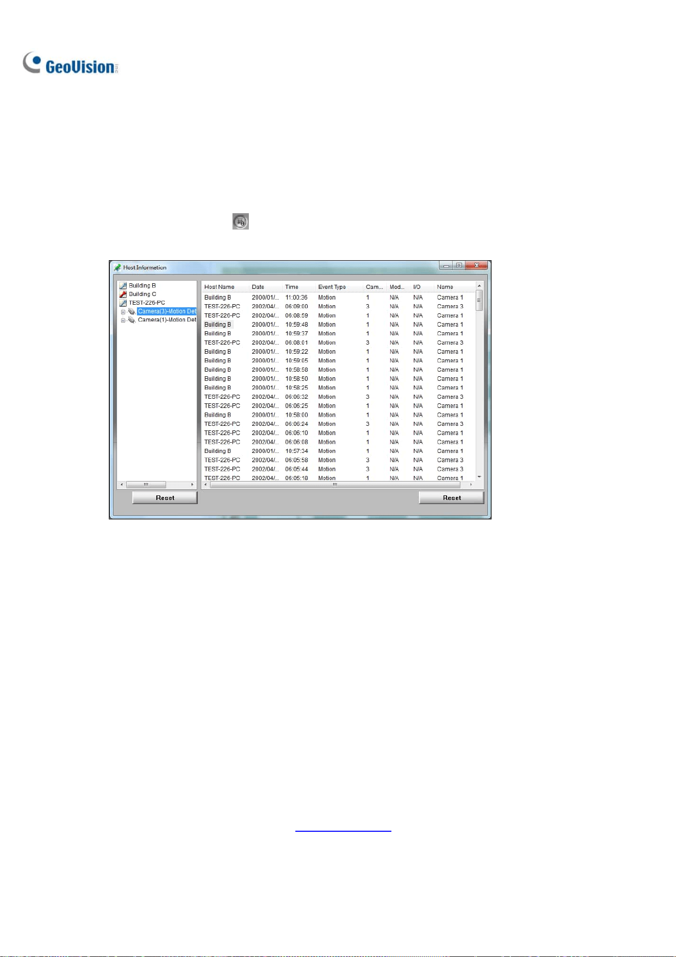
264
8.4.4 Viewing Event List and Playing Back Videos
You can see a list of triggered events on the Host Information window and play back the desired
video(s).
1. Click Host Information
on the Remote E-Map window. The Host Information window
appears.
Figure 8-20
2. For event playback, double-click any motion event on the left panel. The player appears.
3. Optionally right-click the image to access the advance functions of the player.
8.5 E-Map Server
The E-Map Server is an independent program designed to create E-Maps for different hosts. With the
E-Map Server, you can monitor different sites on electronic maps through any computer accessible to
the network.
8.5.1 Installing E-Map Server
You can install GV-E-Map Server from the GeoVision Website
.

E-Map Application
265
8
8.5.2 The E-Map Server Window
Go to Windows Start, find Programs, select eMapServer and click E-Map Server. This window
appears.
Figure 8-21
No. Name Description
1 Start Service Starts the E-Map Server.
2 Stop Service Stops the E-Map Server.
3 New Creates a new E-Map file.
4 Rename Renames the E-Map file.
5 Delete Deletes the E-Map file.
6 Refresh Refreshes the E-Map Server window.
7 Accounts Creates user accounts of the E-Map Server.

266
8.5.3 Setting up E-Map Server
Before starting the E-Map Server, you must create E-Map files and user accounts.
To create E-Map(s), click New (No. 3, Figure 8-21). See Creating an E-Map earlier in this chapter.
To create a user account for the server, click Accounts (No. 7, Figure 8-21).
8.5.4 Connecting to E-Map Server
With E-Map Server, you can monitor different sites on electronic maps through any computer accessible
to the network.
1. Open the Web browser and type the IP address of the E-Map Server.
2. Type the login info of the E-Map Server. You are prompted to select an E-Map (.emp) file.
3. Click OK. The Remote E-Map window appears (Figure 8-16).
4. Click Login
to log into the desired host(s). For details, see Accessing E-Maps of Multiple
Hosts earlier in this chapter.
Note: To log into GV-VMS, make sure the WebCam Server is enabled. See Remotely Accessing
E-Map earlier in this chapter.

267
Chapter 9
Useful Utilities ............................................269
9.1 Dynamic DNS ..................................................................................... 269
9.1.1 Running Dynamic DNS..................................................................................... 270
9.1.2 Registering Domain Name with DDNS.......................................................270
9.1.3 Starting Dynamic DNS.....................................................................................271
9.2 Watermark Viewer ........................................................................... 272
9.2.1 Activating Watermark Protection ...............................................................272
9.2.2 Running Watermark Proof..............................................................................272
9.2.3 The Main Window..............................................................................................273
9.3 Windows Lockup............................................................................... 274
9.3.1 The GV-Desktop Screen.................................................................................. 274
9.3.2 GV-Desktop Features .......................................................................................275
9.3.3 Token File for Safe Mode ................................................................................277
9.4 Authentication Server..................................................................... 278
9.4.1 Installing the Server ........................................................................................278
9.4.2 The Main Window..............................................................................................279
9.4.3 Creating Clients................................................................................................. 280
9.4.4 Creating User Accounts .................................................................................281
9.4.5 Importing Groups and Users from Active Directory ............................. 284
9.4.6 Starting the Server...........................................................................................287
9.4.7 Connecting GV-VMS to the Server ..............................................................289
9.4.8 Remote Access from Control Center and Remote E-Map ................... 291
9.5 Fast Backup and Restore............................................................... 294
9.5.1 Running the FBR Program..............................................................................294
9.5.2 Plugin Component............................................................................................. 295
9.5.3 Customizing the Features ..............................................................................296
9.5.4 Backing up and Restoring Settings ............................................................297
9.6 Bandwidth Control........................................................................... 300
9.6.1 Installing the Bandwidth Control ................................................................300
9.6.3 Allowing Remote Control ...............................................................................302
9.6.4 Connecting to WebCam Server .................................................................... 303
9.6.5 Controlling a Specific WebCam Server .....................................................304
9.6.6 Setting up Bandwidth......................................................................................305

268
9.6.7 Block List Setup ................................................................................................306
9.6.8 General Setup ....................................................................................................307
9.7 Language Setting ............................................................................. 308
9.7.1 Installing the MultiLang Tool ........................................................................308
9.7.2 Revising the Translated Text ........................................................................309
9.7.3 Setting up the UI Language to English .....................................................312
9.8 GV-SD Card Sync Utility ................................................................. 313
9.8.1 Installing GV-SD Card Sync Utility..............................................................313
9.8.2 Setting up GV-SD Card Sync Utility ............................................................ 314
9.8.3 The Main Window..............................................................................................317
9.9 Media Man Tools............................................................................... 318
9.9.1 The Media Man Tools Window ......................................................................318
9.9.2 Viewing Disk Drive Status ............................................................................. 319
9.9.3 Adding a Disk Drive ..........................................................................................321
9.9.4 Removing a Disk Drive ....................................................................................322
9.9.5 Logging in Automatically at Startup ..........................................................323
9.9.6 Setting up LED Panel .......................................................................................323
9.10 Alert Notifications through SNMP Protocol .......................... 326
9.11 Local and Remote Backup .......................................................... 327
9.11.1 Remote Backup ...............................................................................................327
9.11.2 Local Backup ................................................................................................... 327
9.11.3 Advanced Settings .........................................................................................329
9.11.3.1 Advanced Settings for Local Backup...................................................329
9.11.3.2 File Transfer Settings for Local Backup .............................................330
9.12 Report Generator ........................................................................... 332
9.13 GV-Cloud Center ............................................................................. 332

269
Useful Utilities
GV-VMS supports some advanced utilities to enhance the system performance in a security network.
9.1 Dynamic DNS
GV-Dynamic DNS provides domain name registration, making your dynamic IP address point to your
GV-VMS server. The GV-Dynamic DNS will update the server’s IP address to DNS Server every 10
minutes. Even if your server’s IP address changes, you can still locate it by using the registered
domain name.
Note: GV-Dynamic DNS uploads IP addresses over the Internet through ports 80 and 81. If your
GV-VMS server is connected behind a router or firewall, make sure ports 80 and 81 are enabled.
GV-Dynamic DNS will only upload global IP addresses. If your GV-VMS server is using virtual IP, NAT
port mapping should be done first.
IMPORTANT: The DDNS service simplifies the process of trying to connecting an IP video device to
the network. However, GeoVision does not and cannot warrant that the DDNS service will be
uninterrupted or error free. Please read Terms of Service carefully before using the service. Besides
GeoVision, you can also obtain the free DDNS service from these providers: DynDNS.org
and
No-IP.com
.
CHAPTER
9

270
9.1.1 Running Dynamic DNS
GV-Dynamic DNS Service is included in the installation of GV-VMS. Go to Windows Start >
Programs > GV-VMS > DNS Client V2. The DNSClient V2 dialog box appears.
9.1.2 Registering Domain Name with DDNS
1. Click Register on the DNSClient V2 dialog box. The registration page appears.
Figure 9-1
2. Type a username and password and the Word Verification code. The password must be at least 6
characters.
3. Click the Send button. The following message appears.
Figure 9-2
Hostname: Made by registered username and “gvdip.com”. In this example, the hostname is
“http://julia.gvdip.com”. This will be the domain name used to log into your server.
IP Address: Your server’s current IP address. This IP address is updated every 10 minutes.
Note: The domain name .gvdip(xx).com may vary with xx from 01 to 99.

Useful Utilities
271
9
9.1.3 Starting Dynamic DNS
After registering a domain name with GV-Dynamic DNS, enable the DDNS function on your server.
Run DDNS Client V2 (Figure 9-1) and be sure GeoVision software is also enabled at the background.
After typing the Hostname and Password used to enable the Dynamic DNS service, complete the
following settings:
Obtain an IP address automatically: The DDNS server will use any available IP address from
the server or the router.
Use the following IP address: If your server or router has more than one IP address, you can
assign one IP address to connect between the DDNS server and GV-VMS. It is highly suggested
to assign a fixed IP address instead of a dynamic IP address, which will not be accessible for the
DDNS when the IP address is changed.
Run at startup: Select to automatically run the DDNS service at Windows startup.
E-mail Setting:
o Scheme: Select a given situation to receive e-mail notifications.
o Sender: Type the name, e-mail address, username and password of the sender.
o Receiver: Type the recipient’s e-mail address(es). For multiple recipients, add a semicolon
between each e-mail address.
o Mail Server: Type the host name or address of your mail server. Keep the default port 25 or
modify if the mail server uses a different port. Select SSL if your e-mail server requires the
SSL authentication for connection.
o Click the Test button to send a test e-mail to confirm if the settings are correct.
Click Save. The connection information will be displayed.
Note: The DNS Client will not upload the IP address unless the compatible GeoVision software is
running such as GV-VMS. If the IP address of your server is not updated for more than 30 days, your
host name will be deleted automatically.

272
9.2 Watermark Viewer
GV-VMS can embed digital watermarks in video streams for authentication purposes. The watermarks
are encrypted with digital signatures in video streams during the compression stage, ensuring that
images are not edited or damaged after they are recorded. In addition, you can apply the Watermark
Proof, a watermark-checking program included in the installation of GV-VMS, to further verify the
authenticity of the recording.
Note: To run the Watermark Proof application in the backup file on your PC without GV-VMS, you
must register the GeoVision Video Codec manually (go to the recorded files’ location >
GeoCodecReg folder > double-click GeoCodecReg).
9.2.1 Activating Watermark Protection
To enable the watermark protection, click Home > Toolbar > Configure > System
Configure > Record Setting. Select Use Digital Watermark Protection and click OK. GV-VMS will
digitally sign videos during the recording.
Figure 9-3
9.2.2 Running Watermark Proof
1. Go to the GV-VMS folder and run WMProof.exe. The Watermark Proof window appears.
2. Click File from the menu bar, select Open, locate the recorded file (.avi) and click Open. The
selected file is listed on File List (No. 9, Figure 9-4). Alternatively, you can directly drag the file
from the storage folder to the window.
˙ If the recording is unmodified, a check mark will appear in the Pass column.
˙ If the recording is modified or does not contain watermark during recording, a check mark will
appear in the Failed column.
3. To play the recording, double-click the listed file on the window.

Useful Utilities
273
9
9.2.3 The Main Window
Figure 9-4
No. Name Description
1 Open File Opens the recorded file.
2 First Frame Goes to the first frame of the file.
3 Play Plays the file.
4 Previous Frame Goes to the previous frame of the file.
5 Next Frame Goes to the next frame of the file.
6 Previous Watermark Frame Goes to the previous frame that contains watermark.
7 Next Watermark Frame Goes to the next frame that contains watermark.
8 Original vs. Extracted
The Extracted icon should be identical with the Original
icon. If not, it indicates the recording has been tampered.
9 File List Displays the proof results.

274
9.3 Windows Lockup
The GV-Desktop helps you secure your computer while away from your workstation. You may lock up
the Windows desktop while launching a customized GV-Desktop. In the GV-Desktop, users are limited
to run GV-VMS and selected programs.
9.3.1 The GV-Desktop Screen
The GV-Desktop is included in the installation of GV-VMS. Go to Windows Start > Programs >
GV-VMS > Key Lock Utility. The GV-Desktop screen appears.
Figure 9-5
No. Name Description
1 Programs Accesses programs.
2 Settings Adds programs to the Programs menu.
3 Log Off Logs off GV-Desktop.
4 Shut Down Shuts down the computer.
5 Task Manager Views the tasks currently running on your computer.

Useful Utilities
275
9
9.3.2 GV-Desktop Features
Programs
Click the Programs button (No.1, Figure 9-5) to see the program menu. The default programs are
Video Management System (GV-VMS), Repair Database Utility, eMap Editor and Control Center
Service. To add or remove new programs to the menu, see the Settings section later in this chapter. In
the example below, Paint is a new program added to the menu.
Figure 9-6
Settings
Click the Settings button (No.2, Figure 9-5) and type the valid ID and password. This window appears.
Figure 9-7
[Password] Change the password. For the Allow Removing Password System option, see Account
and Password in Chapter 1.

276
[Export Token] See Token File for Save Mode later in this chapter.
[System Menu] Select a desired program and click the Edit button to change its name.
[Customize Menu] Set up the Programs menu as desired. To add a program, click the Add button. In
the Shortcut dialog box, type the program name, click the button next to the field to assign a path and
click OK.
[Administrative Tools] Set up the Programs menu as instructed in Customized Menu option. To run
the added programs configured in the Administrative Tools field, the administrative ID and Password
are required.
[Desktop Type] Select Windows or GV-VMS from the drop-down menu. The selected desktop will
launch the next time when you log into the computer.
Log Off
Click the Log off button (No.3, Figure 9-5) to log off GV-Desktop with a valid ID and password.
Shut Down
Click the Shut Down button (No. 4, Figure 9-5) to shut down your computer with a valid ID and
password.
Task Manager
Click the Task Manager button (No. 5, Figure 9-5) to view the programs which are currently running on
your computer. When you minimize a program, it will be hidden and under operation in the background.
To bring the program back to desktop, double-click the program listed in Task Manager.
Figure 9-8

Useful Utilities
277
9
9.3.3 Token File for Safe Mode
This option in the Settings section lets you export a token file. In case you enter safe mode and are in
the status of the GV-Desktop, this token file allows you to exit from the GV-Desktop and enter the
Windows desktop. To export a token file, follow the steps below.
Exporting the Token File
1. Click the Export Token button (Figure 9-7). The Enter Token Code appears.
2. Type a code in the Token Code field and click OK.
3. In the Save As dialog box, locate a path, type a desired name in the File Name field and click
Save to save the file.
Switching from GV-Desktop to Windows Desktop
1. Click the Settings button on the GV-Desktop. You will be prompted to locate the stored token file
and type the configured token code.
2. When the Settings window (Figure 9-7) appears, select Windows in the Desktop Type field and
exit from the window.
3. Click the Log Off button to log off the GV-Desktop and run the Windows desktop. You need to
locate the stored token file and type the configured token code again.

278
9.4 Authentication Server
GV-Authentication Server is a password and account management system for multiple GV-VMS
systems. Through the Authentication Server, the administrator can create the accounts with different
access rights to a group of GV-VMS systems. Once any GV-VMS is connected to the Authentication
Server, the previous password settings in local GV-VMS will be invalid. Local GV-VMS will submit to
the full control of the Authentication Server.
Note:
1. In addition to GV-VMS / DVR / NVR where the Authentication Server acts as a password and
account management system, the Authentication Server also supports E-Map Server,
GV-Control Center, GV-Edge Recording Manager and GV-Eye app to allow users to access a
specified group of GV-VMS / DVR / NVR hosts through an Authentication user account.
2. GV-Eye V2.8.0 or later and GV-Edge Recording Manager V2.1.0 or later support multiple
GV-Authentication Server connections at a time.
9.4.1 Installing the Server
You can install GV-Authentication Server from Utilities in GeoVision Website
.

Useful Utilities
279
9
9.4.2 The Main Window
Go to Windows Start > Programs > AuthServer > AuthServer. This window appears.
1 2 3
4
5
6 7
8
9 10
11
12
13
Figure 9-9
No. Button Description
1 Add An Area Creates an Area group.
2 Add A Client Creates a client account.
3 Delete An Area / Client Deletes an existing group or client.
4 View/Edit A Client Select a client from the Client List, and click to view / edit it.
5 Find A Client Finds an existing client.
6 Start/Stop Service Starts/Stops the Authentication Server.
7 Server Setup Configures the Authentication Server.
8 Account Setup
Configures passwords and grants permissions to clients. Imports
groups from Active Directory.
9 Log Sets up the Authentication Server Log and opens the log browser.
10 Exit
Exits this window; Logs out Administrator; Changes
Password, imports or exports account information.
11 Connected Client List
Lists the connected clients: GV-VMS / DVR / NVR, E-Map Server,
GV-Control Center, GV-Edge Recording Manager and GV-Eye.
12 Client Information Lists the information of the selected client.
13 Client List Lists the created clients.

280
9.4.3 Creating Clients
You must create and arrange the clients first which user credentials will be centrally managed by the
Authentication Server. To create a list of GV-VMS clients, follow the steps below.
1. To create a GV-VMS client, highlight the Host List from the left pane and click the Add A Client
button
. The Client Information dialog box appears.
Figure 9-10
2. Type the client’s information and select Automatic get connection info. The Name must match
that of local GV-VMS.
3. Optionally select Manual Setting and type the IP address of the Authentication Server. Keep the
default ports or modify them if necessary.
Figure 9-11
4. Click OK.

Useful Utilities
281
9
Tip: To view the name of your GV-VMS server, select Toolbar
> Configure > System
Configure > General Setting.
Figure 9-12
5. To create another client, repeat the steps above.
6. You can also arrange multiple clients under a group by highlighting a list and clicking the Add An
Area button (No. 1, Figure 9-9). The created group appears under the selected List.
9.4.4 Creating User Accounts
To create user accounts with different access rights and assign the user accounts to a group of
GV-VMS clients, follow the steps below.
1. Click the Account Setup button (No.8, Figure 9-9) > Password Setup. The Password Setup
dialog box appears.
2. Create a user account. Refer to Account and Password in Chapter 1.
Note: The Administrator has the authority of changing the passwords of any accounts.

282
3. To assign the created user to a group of GV-VMS clients:
A. Click the Group Setting button.
Figure 9-13
B. In the Valid Group List window, click the New Group button.
Figure 9-14
C. In the DVR Group Information window, name the group, select the GV-VMS clients to be
added to the group. Click OK.
Figure 9-15
D. Click OK again to return to the Password Setup window.

Useful Utilities
283
9
E. Use the Valid Group drop-down list to select the created group. The user will be able to log in
the assigned GV-VMS clients.
Figure 9-16
4. Optionally use the following functions to arrange the user and client accounts.
A. Right-click a user account to have two options. The Apply setting to option will apply the
same settings to a specific user account. The Apply setting to group option will apply the
same settings to all user accounts under the same account level.
Figure 9-17
B. Right-click a client account to have two options. The Apply setting to other DVR(s) option
allows you to apply the same settings to all clients under the same user account. For this
example, the settings of Building A client will be applied to all Building B, C and D clients. The
Copy option allows you to copy and paste one client’s settings and any client.
Figure 9-18

284
9.4.5 Importing Groups and Users from Active Directory
To create user accounts efficiently, you can import groups and users from Microsoft’s Active Directory
to Authentication Server. You will need to install Active Directory on Windows Server and set up users
into groups before following the steps below.
Note: User accounts in Active Directory need to be grouped into Groups settings first as only groups
can be imported into Authentication Server.
1. Run Active Directory Domains and Trusts in Windows Server by clicking the Start menu and
opening Administrative Tools.
2. Right-click your local Active Directory system and select Manage. The Active Directive Users and
Computers dialog box appears.
Figure 9-19
3. On the View menu, select Advanced Features.

Useful Utilities
285
9
Note: If you use Windows Server 2008 instead of Server 2012, skip this step.
4. Right-click the folder saved with the user accounts or groups and select Properties.
Tip: You can change the query parameters or show all items for each folder by clicking View and
selecting Filter Options.
5. Select the Attribute Editor tab, double-click the attribute distinguishedName and copy the value
like OU=persons,DC=FAE,DC=com. You will need to paste the value at step 8, C to assign the
folder to import the user accounts or groups.
6. In the Authentication Server, click the Account Setup button (No.8, Figure 9-9) and select Active
Directory Setup. This page appears.
Figure 9-20
7. Under Source Database, select Active Directory to enable the function.
8. To connect to the server with Active Directory:
A. Type the Server IP Address and the Port number of the server.

286
B. To log into the server using your current login information, select Connect with the current
login information. To log into the server using the login information of its administrator, select
Connect with administrator login information and type the user name and password.
C. Paste the value of distinguished name you copied at step 5 respectively to Group / Users
Search Base.
D. Click Test Connection to see if you can connect to the server with Active Directory.
9. To assign groups in Active Directory to User, Power User or Supervisor authority levels:
A. Click the Assign Authority Level button. This dialog box appears.
Figure 9-21
B. Select the groups detected in Active Directory from the Undefined Group list and use the
arrow buttons
to assign the groups to User, Power User or Supervisor level.
C. Click OK to import the user data into the Password Setup window.
10. To automatically update changes to user data in Active Directory, click Auto Update and specify
the update frequency in minutes.
11. Click OK and restart Authentication Server to apply the settings.

Useful Utilities
287
9
9.4.6 Starting the Server
To configure the server and start the service, follow the steps below.
1. Click the Server Setup button (No. 7, Figure 9-9). This dialog box appears.
Figure 9-22
2. Under Security Setting, type the Authorized ID and Authorized Password which will be used for
the client GV-VMS to log into the Authentication Server.
3. Click OK to apply the settings.
4. Click the Start/Stop Service button (No. 6, Figure 9-9) to start the services.
Optionally, you can configure the following settings before starting the Authentication Server:
[Network Setting]
Server Port: The default port number is 3663. To use UPnP for automatic port configuration to
your router, click the Arrow button. For details, see UPnP Settings in Chapter 7.
Automatic Failover Support: Select and click the Setting button to configure up to 2
Authentication Servers in case the primary Authentication Server fails. If fails, the second or the
third server will take over the connection from clients and provide uninterrupted services. Note the
settings of Authorized ID and Authorized Password on the failover server must match those of the
primary server.

288
Tip: To set up the failover Authentication Server, you can export the current settings by using the
Export Account and Import Account functions in the Exit button.
Note: Once the primary Authentication Server is ready to resume the services, close the failover
Authentication Server so the connection from clients can move back to the primary.
[Security Setting]
Enhance network security: Strengthen network security on Authentication Server.
Enable IP White List: Click Edit to create a list of IP addresses only to establish connection with
Authentication Server.
[Server Setting]
Auto run server service upon startup: Starts the service automatically upon the startup of
Authentication Server.
Notify when DVR is disconnected from server: Notify the Authentication Server with a pop-up
window when the GV-VMS is disconnected with the Authentication Server.

Useful Utilities
289
9
9.4.7 Connecting GV-VMS to the Server
To configure the GV-VMS in order to access the Authentication Server remotely through a network
connection, follow the steps below.
1. On the main screen of GV-VMS, click User
> Password Setup > Remote Authentication
Setup. The Setup Remote Authentication Server dialog box appears.
Figure 9-23
2. Select Use Remote Authentication and optionally select:
[When Remote Authentication Server Off-line]
Allow local supervisor to stop use Remote Authentication System: Allow the local
supervisor to stop the Authentication application when the connection fails with the
Authentication Server. Note if the option is disabled and the connection fails with
Authentication Server, the local supervisor will not be able to log into the GV-VMS, and the
dialog box will not be accessible until the connection resumes.
Allow user to use local account login remote application: Allow local users to access
remote applications with their previous password and ID settings when the connection with the
Authentication Server fails.
Login with authentication server backup account: Keep using password settings created
on the Authentication Server even though the connection with the server fails.
3. Click Setup Server. The Remote Authentication dialog box appears.
4. Type the IP address and port of the Authentication Server.
5. Type the Authorized ID and Authorized Password of the Authentication Server.
6. Click OK to start the connection. When the connection is established, the previous password
settings in GV-VMS will be invalid.

290
7. Press [L] on the keyboard to call up the Login dialog box. The icon
indicates that the
connection is established.
Figure 9-24
As long as the Authentication Sever works, the Login dialog box will appear upon the starting of
GV-VMS. Type the user account created on the Authentication Server to log into the GV-VMS.
Note: The disconnection icon will appear on the Login dialog box (Figure 9-24) when one of the
following situations occurs:
1. The login ID and Password do not match any of the user IDs and Passwords created on the
Authentication Server.
2. The client name does not match the location name of GV-VMS (Figure 9-12).
3. The network connection encounters traffic problems.

Useful Utilities
291
9
9.4.8 Remote Access from Control Center and Remote E-Map
The Authentication Server supports E-Map Server, GV-Control Center, GV-Edge Recording Manager,
and GV-Eye to allow users to access a specified group of GV-VMS hosts through an Authentication
user account.
You must first set up remote authentication on E-Map Server and GV-Control Center. After the E-Map
Server and GV-Control Center are connected to the Authentication Server, the user will be prompted to
log in with the user ID and password you created on the Authentication Server. Once the user logs in, a
list of GV-VMS hosts authorized to the user account will be displayed, and the user will be able to view
the assigned cameras.
Setting up Authentication Server
You need to create and arrange client accounts of E-Map Server, GV-Control Center, GV-Edge
Recording Manager, or GV-Eye under their separate lists on the Authentication Server window (Figure
9-9).
1. In the Client List field, click the E-Map Server List or Client List, and click the Add A Client
button (No. 2, Figure 9-9). The Client Information dialog box appears.
2. Type the name and information of the desired software or mobile app to be connected. The name
does not need to match the location name of the software or mobile app.
3. Click OK to add the client.
Accessing from E-Map Server
The E-Map Server can access the user account setting of the Authentication Server.
1. Run the E-Map Server. For details, see E-Map Sever in Chapter 8.
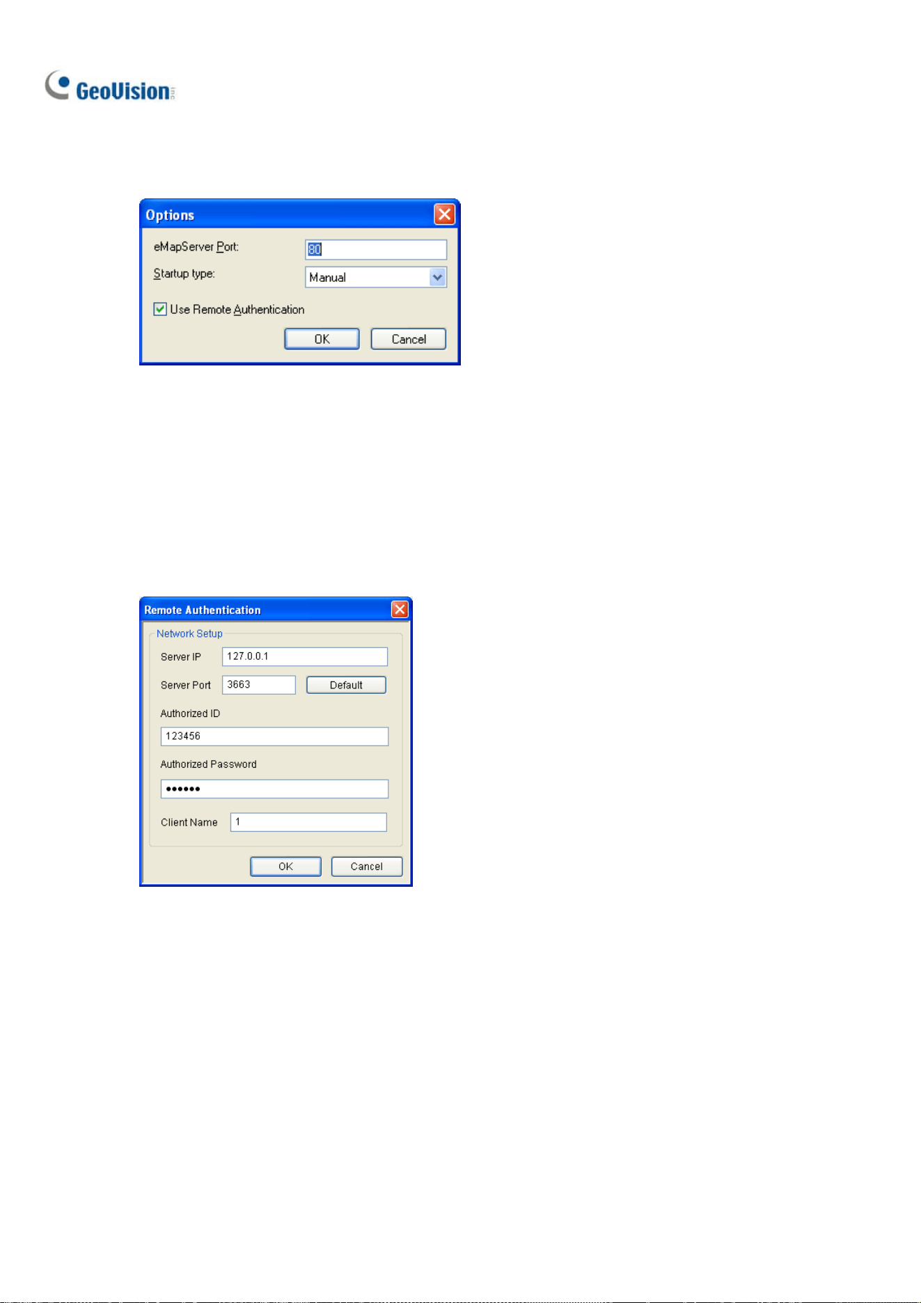
292
2. In the E-Map Server window, click Tools on the menu bar, and select Options. This dialog box
appears.
Figure 9-25
3. Select Use Remote Authentication.
4. To enable the Authentication Server service to start automatically at Windows startup, select
Automatic. Keep the E-Map Server Port 80 as default or modify if necessary.
5. Click OK to apply the settings.
6. In the E-Map Server window, click Tools on the menu bar and select Remote Authentication.
This dialog box appears.
Figure 9-26
7. Type the IP address, authorized ID and authorized password of the Authentication Server, as well
as the E-Map Server’s client name created on the Authentication Server, and then click OK.
8. In the E-Map Server window, click Tools on the menu bar and select Start Service to start the
E-Map Server.
9. When you log into the E-Map Server, type the user ID and password created on the Authentication
Server. A list of assigned GV-VMS clients to the user will be displayed.

Useful Utilities
293
9
Accessing from GV-Control Center
The GV-Control Center can access account settings of the Authentication Server.
Note: The Authentication Server only supports GV-Control Center V3.1.2.0 or earlier.
1. Run the GV-Control Center. For details, see GV-Control Center User’s Manual.
2. On the Host List, right-click Host List by ID and select Remote Authentication Setup. A dialog
box appears.
3. Type the IP address, authorized ID and authorized password of the Authentication Server, as well
as Control Center’s client name created on the Authentication Server, and then click OK to enable
connecting to the Authentication Server.
4. To access the Authentication Server account settings, on the Host List, right-click Host List by ID
and select Get Host List by ID. A dialog box prompts you for ID and password.
5. Type a user ID and password created on the Authentication Server, and click OK. A list of
assigned GV-VMS hosts to the user will be displayed.
Accessing from GV-Edge Recording Manager / GV-Eye
For details, see Chapter 8 in GV-Edge Recording Manager User’s Manual or Chapter 13 in GV-Eye
Installation Guide.

294
9.5 Fast Backup and Restore
With the Fast Backup and Restore (FBR) solution, you can change interface skin and customize
features to suit personal preference, as well as backing up and restoring your configurations in
GV-VMS.
9.5.1 Running the FBR Program
Go to Windows Start > Programs > GV-VMS > Fast Backup & Restore Main System. You will be
prompted to enter a valid ID and Password of GV-VMS, and then this window will appear.
Figure 9-27

Useful Utilities
295
9
9.5.2 Plugin Component
You can add programs to your GV-VMS to expand the applications.
1. In the FBR window (Figure 9-27), click the Plugin Component icon. This dialog box appears.
Figure 9-28
2. Click Add. The Add New Item dialog box appears.
Note: For some applications, type /FBR in the Parameter column if necessary.
3. Type the name of the desired application, locate its path and click OK.
4. To add more applications, repeat steps 1 to 3 and click OK in the User Define dialog box.
5. To access the added applications, run the GV-VMS, click Home
> Toolbar > Tools
, point to Plugin and select a desired application.

296
9.5.3 Customizing the Features
Not every feature may be of equal interest to you. You can specify which features are to be displayed
at system startup.
1. In the FBR Window (Figure 9-27), click Customize Features. This dialog box appears.
Figure 9-29
2. Expand the folder(s) and click the function(s) you want to disable in the GV-VMS.
3. Click OK to save the settings.
4. Restart GV-VMS for the settings to take effect.

Useful Utilities
297
9
9.5.4 Backing up and Restoring Settings
You can back up the configurations you made in the GV-VMS, and restore the backup data to the
current system or import it to another GV-VMS.
Backing up the settings
1. In the FBR window (Figure 9-27), click the Backup GV-VMS Settings or Restore Defaults icon,
and select Backup Current System.
2. Select which settings you want to back up and click the Next Step button
.
3. In the Save As dialog box, select the destination to store the backup file. When the backup is
complete, the “Successfully Backup GV-VMS System Settings” message will appear:
Restoring the System
You can restore the current system with the backup of configuration file. Also, you can copy this
backup file to configure another system with the same settings as the current system.
1. Open the backup file (*.exe) you previously stored. A valid ID and password are required to
display this window.
Figure 9-30
2. Click the Restore GV-VMS System icon and then select which backup settings you want to
restore.

298
3. Click the Next Step button
to start restoring.
4. When the restoration is complete, the “Successfully Restore GV-VMS System Settings” message
will appear.
Scheduling Configuration Backup
You can now set up a regular schedule with password protection to back up the GV-VMS
configurations you made.
1. Go to Windows Start > Programs > GV-VMS > Fast Backup & Restore Main System. Type a
valid ID and Password of GV-VMS as prompted.
2. Click Backup GV-VMS Settings or Restore Defaults > Schedule Setup.
3. Select Active Schedule.
Figure 9-31
4. Select a desired schedule type.

Useful Utilities
299
9
5. Select desired options for backup.
Password: Back up all the user accounts and password settings of GV-VMS.
General: Back up all the settings of video analysis, IP devices, system configurations,
Content List, E-Map, GV-Keyboard / GV-Joystick, and System Log.
Schedule: Back up the recording schedule configuration.
Network: Back up the network configuration of connection to VSM (Vital Sign Monitor) and
to Center V2.
6. Type a user ID and password in the Login Information section. The ID and password must be
identical with that of a user account created in GV-VMS. You will need to use this ID and password
to restore the backup file.
7. Locate a path to save the backup contents.
Restoring Defaults
To restore the system default, click the Backup GV-VMS Settings or Restore Defaults icon (Figure
9-27), select Restore Defaults and follow the on-screen instructions to complete the process.

300
9.6 Bandwidth Control
The Bandwidth Control is an independent application that controls and monitors the network traffic of
the WebCam Servers. It has the following features:
Manage up to 5 GV-VMS systems
Get bandwidth usages of every Webcam Server and every user
Set bandwidth thresholds for specific users and IP addresses
IP black and white list
Kick unwanted users
9.6.1 Installing the Bandwidth Control
You can install GV-Bandwidth Control Client Site from Utility in GeoVision Website.
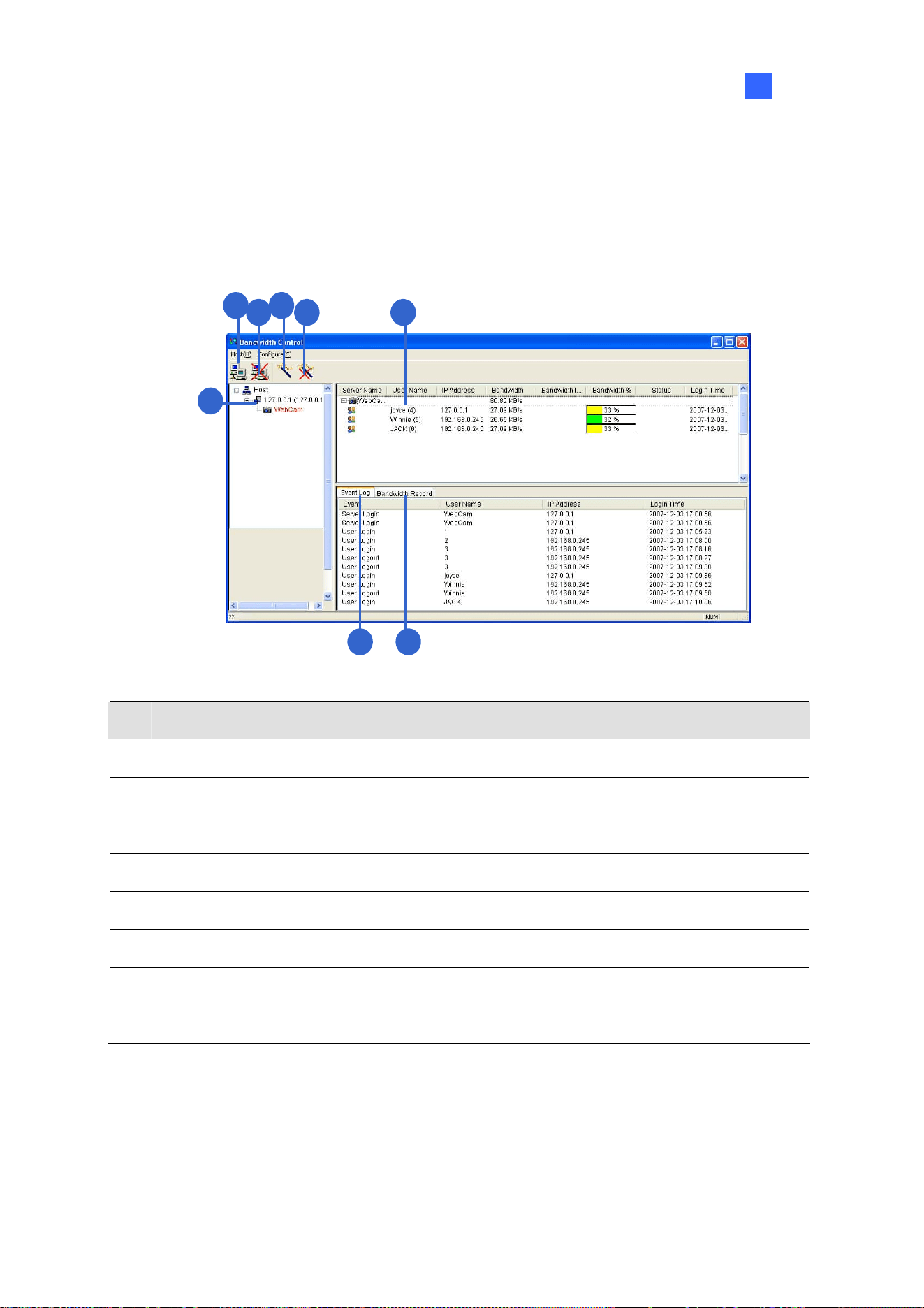
Useful Utilities
301
9
9.6.2 The Main Window
After the installation is complete, double-click the Bandwidth Remote Control icon created on the
desktop. The Bandwidth Control window appears.
1
4
3
8
52
67
Figure 9-32
No. Name Description
1 Connection Builds the connection to a WebCam Server.
2 Disconnect Stops the connection to a WebCam Server.
3
Get Control Obtains the right to remotely control a WebCam Server.
4
Give Up Control Ceases controlling WebCam Servers and users.
5 User List Displays the connected users and their status
6 Bandwidth Record Displays the network traffic in graph display.
7 Event Log Records activities of WebCam Servers and users.
8 Host List Displays all WebCam Servers to be connected.

302
9.6.3 Allowing Remote Control
To allow the remote bandwidth control to the WebCam Server, follow the steps below.
1. On the main screen of GV-VMS, click Home
> Toolbar > Configure > Network
> WebCam Server. This dialog box appears.
Figure 9-33
2. Under the General tab, select Run Bandwidth Control server. After this option is enabled, on
the Control Center Server option list, the Bandwidth Control Service is marked with a check.
Figure 9-34

Useful Utilities
303
9
9.6.4 Connecting to WebCam Server
1. Click the Connection button (No. 1, Figure 9-32) on the toolbar. This dialog box appears.
Figure 9-35
2. To add a WebCam Server to be connected to, click Add.
3. Type the host name, IP address, user name and password of the WebCam Server. Modify the
port if necessary.
4. Click OK. After the connection is established, the WebCam Server shows up in the Host List.
5. You can add up to 10 WebCam Servers by repeating above steps.
6. To stop the connection, select the host and click the Disconnect button (No. 2, Figure 9-32). The
host will be deleted from the host list.
7. Up to 5 users of the Bandwidth Control programs can connect to a single WebCam Server for
network traffic monitoring. However, only one user has the access to bandwidth settings. When
this user clicks the Give Up Control button (No. 4, Figure 9-32), the user no longer controls the
WebCam Server. Whoever clicks the Get Control button (No. 3, Figure 9-32) first has access to
bandwidth settings. For bandwidth settings, see Controlling a Specific WebCam Server later in
this chapter.

304
9.6.5 Controlling a Specific WebCam Server
To disconnect a login user or set the bandwidth limit for a specific user, right-click the user to have the
options below:
Figure 9-36
Kick: Disconnect the user from the WebCam Server.
Block IP: Prohibit the user from connecting to the WebCam Server. To use the function, the
Enable IP Black List option (Figure 9-39) must be selected first.
Bandwidth Setup: Select By Username to specify a bandwidth limit for the user, or select By IP
to limit the bandwidth used by the IP address. This setup dialog box will appear. In this example,
an IP address is selected for bandwidth limit setup. Select Bandwidth Setup, specify a
bandwidth limit and click OK.
Figure 9-37

Useful Utilities
305
9
9.6.6 Setting up Bandwidth
You can manage the bandwidth of multiple hosts, allocated to a WebCam Server, by specifying certain
users and IP addresses when your network is busy or heavily loaded.
1. Click Configure on the menu bar and select Bandwidth Setup.
2. In the Bandwidth Setup dialog box, select the desired WebCam Server and click OK. This dialog
box appears.
Figure 9-38
Bandwidth limit: Select to define the total bandwidth that the WebCam Server will be
allowed to use on your network.
By IP: Click Add and specify an IP address or a range of IP addresses and its bandwidth
limit.
By Username: Click Add and specify the user name and its bandwidth limit.
Note: If you have already specified the total bandwidth to a WebCam Server, it is prioritized before
the bandwidth limits set to user names and IP addresses.

306
9.6.7 Block List Setup
Two types of block lists are provided to restrict the access to a WebCam Server: permitting and
denying a specified range of IP address to establish the connection. Note that only one type of block
list can be used at a time.
1. Click Configure on the menu bar and select IP White / Black List Setup. A dialog box prompts for
you to select a host.
2. In the IP White / Black List Setup dialog box, select the desired WebCam Server and click OK.
This dialog box appears.
Figure 9-39
3. Select a desired type of block list and click Add to define the IP addresses.
Enable IP White list: Allow the defined range of IP addresses to establish the connection to
the WebCam Server.
Enable IP Black list: Prohibit the defined range of IP addresses from establishing the
connection to the WebCam Server.
4. Click OK to apply the settings.

Useful Utilities
307
9
9.6.8 General Setup
You can set up sound alarm for user log-in, or change the real-time graph display of network traffic.
Click Configure on the menu bar and select General Setup. This dialog box appears.
Figure 9-40
Auto Connect: Enable the application to connect to previously connected hosts automatically
next time the application restarts,
User Login Alarm: Enable the computer alarm on when a user logs in.
Bandwidth Display Option: Set the color of bandwidth save, grid lines of the graph and the
background color of the graph.
Number of Grid Line: Set the number of grid lines to be displayed on the graph.
You can click the Bandwidth Record tab in the Bandwidth Control window to view the network traffic in
graph.
Figure 9-41

308
9.7 Language Setting
The user interface has been translated from English into 30 other languages. If you find the translation
to be unsuitable and would like to correct it, use the MultiLang Tool to revise the translation. Next, you
can apply the revised text to the applications and export a MRevise.exe file to make the same revision
on another computer. You can also send the revision back to GeoVision to have the revision included
in future software release.
9.7.1 Installing the MultiLang Tool
You can install GV-MultiLang Tool from Utility in GeoVision Website
.

Useful Utilities
309
9
9.7.2 Revising the Translated Text
Revising the Translated Text
1. After completing the installation, close all GeoVision applications, go to Windows Start >
programs > MultilingualConfig. This dialog box appears.
Figure 9-42
2. Click Language and select the language of the text you want to revise.
3. Click Version to select the version of the GV-VMS that you want to revise.
4. In the Search field, type all or part of the text in English or the target language and click Search.
The results are displayed.
Note: The search is case sensitive.
5. Double-click the text you want to revise. This dialog box appears.
Figure 9-43

310
6. Revise the translated text and click OK.
Note:
1. It is recommended to revise an entire sentence at a time instead of simply sear
ching a single
word and replacing the word in all other strings.
2. The text may contain symbols such as %d or \n that instruct the application to perform certain
functions. Be careful not to change the symbols in the translated text.
3. Before making any revision, click Tools and select Revision Note to read the revision
instructions.
Applying the Revised Text
1. To apply the revised translation to the applications, click Save. This dialog box appears.
Figure 9-44
Note: The system will automatically locate the corresponding files on your computer and replace with
the revised translation for the following applications: GV-VMS, Authentication Server, Bandwidth
Control Client Site, Center V2, Dispatch Server, Fast Backup and Restore (FBR), GV-IP Device
Utility, MCamCtrl Utility, Remote E-Map and Remote ViewLog.
2. Click OK. The message “Do you want to apply the revised multilingual texts to another folder?”
appears. If the storage path for the application has been changed or if the associated application
is not listed in the dialog box, click Yes and select the folder of the application.

Useful Utilities
311
9
Exporting the Revised Text
1. To export the revision as an executable file, click Tools > Export > Export executable file. You
can copy the .exe file to another computer and apply the same translation revision by running
the .exe file.
2. To report the translation revision back to GeoVision:
If your default mail client is Outlook, Outlook Express or Mozilla Thunderbird, click Tools,
Export and Send Report to send the revision.
If your default mail client is not set up or supported, click Tools, Export and Export text file,
and email the exported text file to gvlocalize@geovision.com.tw
.
3. For the distributors to duplicate Software DVD with the translation revision,
Copy and paste all the contents of Software DVD to your computer.
Export the revised translation file and rename the file as MRevise.exe.
Move MRevise.exe to the location you saved the contents of Software
DVD :\Software\Translation Revision.
Duplicate the Software DVD with the MRevise.exe file.
Test the Software DVD by clicking 10. Import Translation Revision from the Install Program
window to apply the translation revision.

312
9.7.3 Setting up the UI Language to English
The default user interface (UI) language of the following GeoVision software and applications is set
according to the region detected. You can install the Set Language tool to set the UI language to
English.
GV-VMS
GV-Fast Backup and Restore Multicam System
ViewLog
GV-Remote ViewLog
GV-IP Device Utility
GV-Center V2
GV-Dispatch Server
GV-Control Center
GV-Remote E-Map
You can install GV-Set Language tool from Utility in GeoVision Website
.
1. In the Configure window, select English from the Language drop-down list.
Figure 9-45
2. Click OK and restart your GeoVision software or application to enable the English UI.

Useful Utilities
313
9
9.8 GV-SD Card Sync Utility
GV-SD Card Sync Utility allows you to download videos from the Micro SD card inserted in the GV-IP
Camera. When the connection between GV-IP Camera and GV-VMS is lost, recordings are
automatically saved to the memory card inserted in the GV-IP Camera. To automatically synchronize
and download recordings from the micro SD card to a local folder, install and execute the program on
GV-VMS.
Note:
1. GV-SD Sync Card Utility is only supported by GV-IP Cam H.264 V1.11 or later, GV-IP Cam
H.265 V1.00 or later, GV-BX2600 V1.00 or later, GV-PPTZ7300 V1.01 or later, and GV-SD2411
/ BX12201 / FER12203 V1.01 or later.
2. It is recommended to keep GV-SD Card Sync Utility running in the background to automatically
synchronize and download videos.
3. Besides the syncing SD card using GV-SD Card Sync Utility, GV-VMS also supports the Sync
recording from camera SD card when reconnected function; see 1.3.1 Setting up Global
Recording Settings for All Cameras.
9.8.1 Installing GV-SD Card Sync Utility
You can install GV-SD Card Sync Utility from Utility in GeoVision Website.

314
9.8.2 Setting up GV-SD Card Sync Utility
1. Run the GV-SD Card Sync Utility. The main window and the Setting window appear. The Setting
window pops up automatically upon first execution. Otherwise, click the Setting button
on the
main window
.
Figure 9-46
2. To configure synchronization, network and startup settings, select the Synchronization tab on
the Setting window. This page appears.
Figure 9-47

Useful Utilities
315
9
[Synchronization]
Synchronize automatically at an interval: Automatically synchronize videos from micro SD
cards to a local folder at the specified interval.
Synchronize automatically at: Automatically synchronize videos from micro SD cards to a local
folder at the specified time.
Download Audio Files: Download audio files along with the video files. This option is enabled
by default.
[Network]
Max. download speed of each device (Kb/sec): To make sure the bandwidth is not completely
taken up while downloading files from the memory card, specify a maximum download speed. If
you do not want to set a bandwidth limit, type 0.
[General]
Start up automatically at Windows login: Automatically launch GV-SD Card Sync Utility when
Windows starts up.
3. To configure the storage and recycling settings, select the Storage tab on the Setting window.
This page appears.
Figure 9-48
Note: By default, downloads are saved to :\GvSDCardSync and are not recycled automatically.

316
[Recycle]
Recycle when the storage space is less than (GB): Specify a minimum free space of your
local storage for file recycling.
Keep the downloaded files for (Days): Specify the number of days to keep the download files
at the local hard drive.
[Storage Location]
To configure the storage path, click the button next to the location field and specify a storage location.
4. Click OK to save the configuration and exit the Setting window.

Useful Utilities
317
9
9.8.3 The Main Window
After installing GV-SD Card Sync Utility, point to Start > Programs > GV-SDCardSync > click
to launch the program. This window appears.
1
4
2
5
3
6
Figure 9-49
No. Name Description
1 Play Video
Plays downloaded recordings of the selected GV-IP Cameras using the
ViewLog player. For details, see Chapter 4 Video Playback.
2 Setting
Configures settings of synchronization, network, storage location and
recycling criteria. See Running the GV-SD Card Sync Utility earlier in
this chapter.
3 Sync all devices
Manually synchronizes and downloads the recording files saved in
GV-IP Camera.
4 IP Camera Tab Shows information of GV-IP Camera connected to GV-VMS,.
5 Log Tab
Displays up to 100 event entries of GV-SD Card Sync Utility. Once the
entries are full, recycling will start from the oldest file.
6 Storage Space Shows the storage space of the designated hard drive.
Note:
1. The synchronization time is recorded according to the system time of GV-IP Camera.
2. The logs are deleted once GV-SD Card Sync Utility is re-activated.

318
9.9 Media Man Tools
The Media Man Tools program provides a hot-swap feature, allowing a non-stop recording. You can
add and remove a hot-swap or portable hard drive to the GV-VMS system without interrupting its
monitoring. When the new drive is added, it will be configured to the recording path automatically.
Additionally, you can back up the ViewLog player and database files to play back at any computer.
Note: The minimum disk capacity for the hot-swap feature is 32 GB.
9.9.1 The Media Man Tools Window
This program comes with the installation of GV-VMS. Click Drive C in My Computer, select the
GV-VMS folder, and then select Media Man Tools. This window will appear.
Figure 9-50
No. Name Description
1 Exit Closes or minimizes the Media Man Tools window.
2 View Refreshes the disk drive status shown in this window.
3
Tools
Sets up the LED panel and automatically logs in the Media Man Tools
window.
4 Display Details
Select the option to view the status and information of the disk drives. For
details, see Viewing Disk Drive Status later in this section.
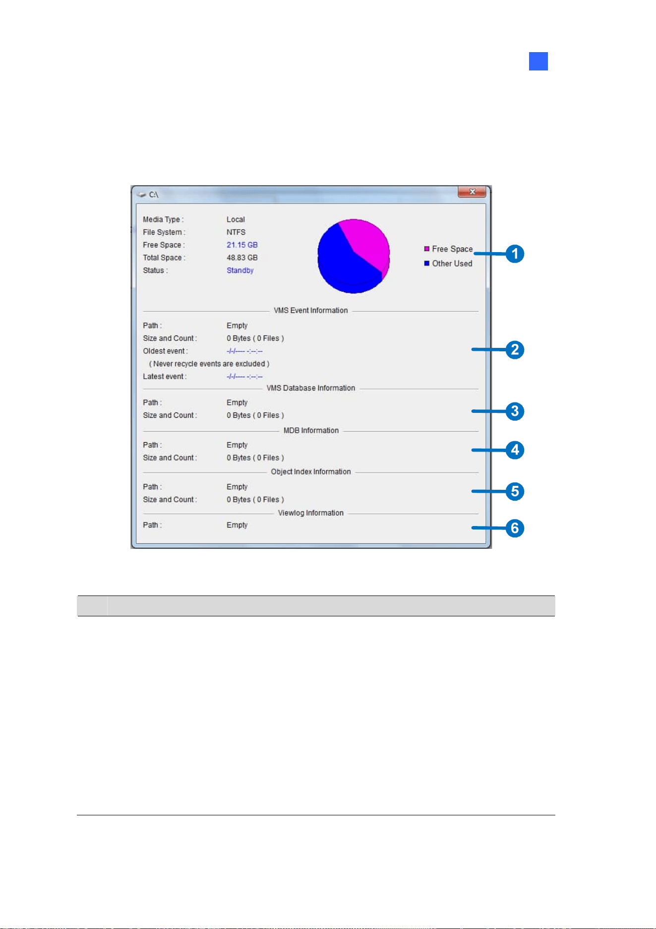
Useful Utilities
319
9
9.9.2 Viewing Disk Drive Status
To view the detailed information of a drive, check Display Details (No. 4, Figure 9-50) in the desired
drive section. The status window will appear.
Figure 9-51
No. Name Description
1 Disk Properties
Indicates disk information.
In “Media Type,” two messages may appear:
LAN: indicates a network hard drive is connected.
Local: indicates a local hard drive is connected.
In “Status”, three messages may appear:
Standby: indicates the hard drive already specified as the
recording path.
Unused: indicates the hard drive not specified as the recording
path.
Recording: indicates the files are being recorded to the disk.

320
No. Name Description
2 VMS Event Info
Indicates the path, size and number of recorded events; the dates of the
oldest and latest events.
3
VMS Database Info Indicates the path, size and number of the ViewLog Event List log files.
4
MDB Info Indicates the path, size and number of System Log files.
5 Object Index Info Indicates the path, size and number of Object Index files.
6 ViewLog Info Indicates the location you have backed up the EZ ViewLog player.
Note: The VMS Event Info updates every minute. The MDB Info, VMS Database Info, Object Index
Info and ViewLog Info update as data changes.

Useful Utilities
321
9
9.9.3 Adding a Disk Drive
1. Click Drive C in My Computer, select the GV-VMS folder, and select the Media Man Tools.
2. Insert a hot-swap hard drive or plug a portable hard drive to your computer. This dialog box
appears.
Figure 9-52
3. Select Add to recording path and select the storage group from the drop-down list.
4. If there are recording files saved on the hard drive, you may select the options of Delete all
events, Delete all database files or Delete all object index files.
5. Click OK to automatically configure the hard drive to the recording path.
To verify the hard drive is added successfully, check if the “Status” of the drive displays Standby
(see Figure 9-50).
Tip: To add a local drive to the recording path, right-click the desired drive on the Media Man Tools
window (Figure 9-50) and select Add for recording.

322
9.9.4 Removing a Disk Drive
To remove a disk drive from the recording path, right-click the desired drive on the Media Man Tools
window (Figure 9-50), and select Remove from recording path. This dialog box will appear. You can
export related database files with the recordings on the hard drive. You can also export the ViewLog
player which allows you to play back the recordings on any computer.
Figure 9-53
Export ViewLog Player:
Export ViewLog with database files: Exports the ViewLog player together with ViewLog
Event List log files (.db files), related to the recordings on the hard drive.
Export database files only: Exports ViewLog Event List log files (.db files) only if the
ViewLog program already exits on the hard drive.
Export System Log database files: Exports the system log files (.mdb files), related to the
recordings on the hard drive.
Export Object Index files: Exports the Object Index files, related to the recordings on the hard
drive.
[…] button: If you want to change the default folder “Viewlog” created on the hard drive, click the
button.
Note: Removing the hard drive will affect ViewLog database. To restore these events, add the hard
drive back to the system and run Repair Database Utility.

Useful Utilities
323
9
9.9.5 Logging in Automatically at Startup
To automatically log in and minimize the Media Man Tools window at Windows startup, follow these
steps:
1. Click Tools on the menu bar, and select Auto login at Windows startup. A dialog box appears.
2. Type the ID and password of the GV-VMS for automatic login in the future.
3. If you want to minimize the Media Man Tools window to the system tray at startup, select Auto
minimize at startup.
4. Click OK.
9.9.6 Setting up LED Panel
A LED panel on the screen provides a quick indication of the activity status of hard disk drives.
Figure 9-54
LED Color Description
Gray No HDD is assigned to this LED.
Green A HDD is assigned to this LED.
Red The HDD is full.
Flashing Green
GV-VMS is recording or the video / audio files are played back in
ViewLog.
Flashing Red The HDD is recycling.
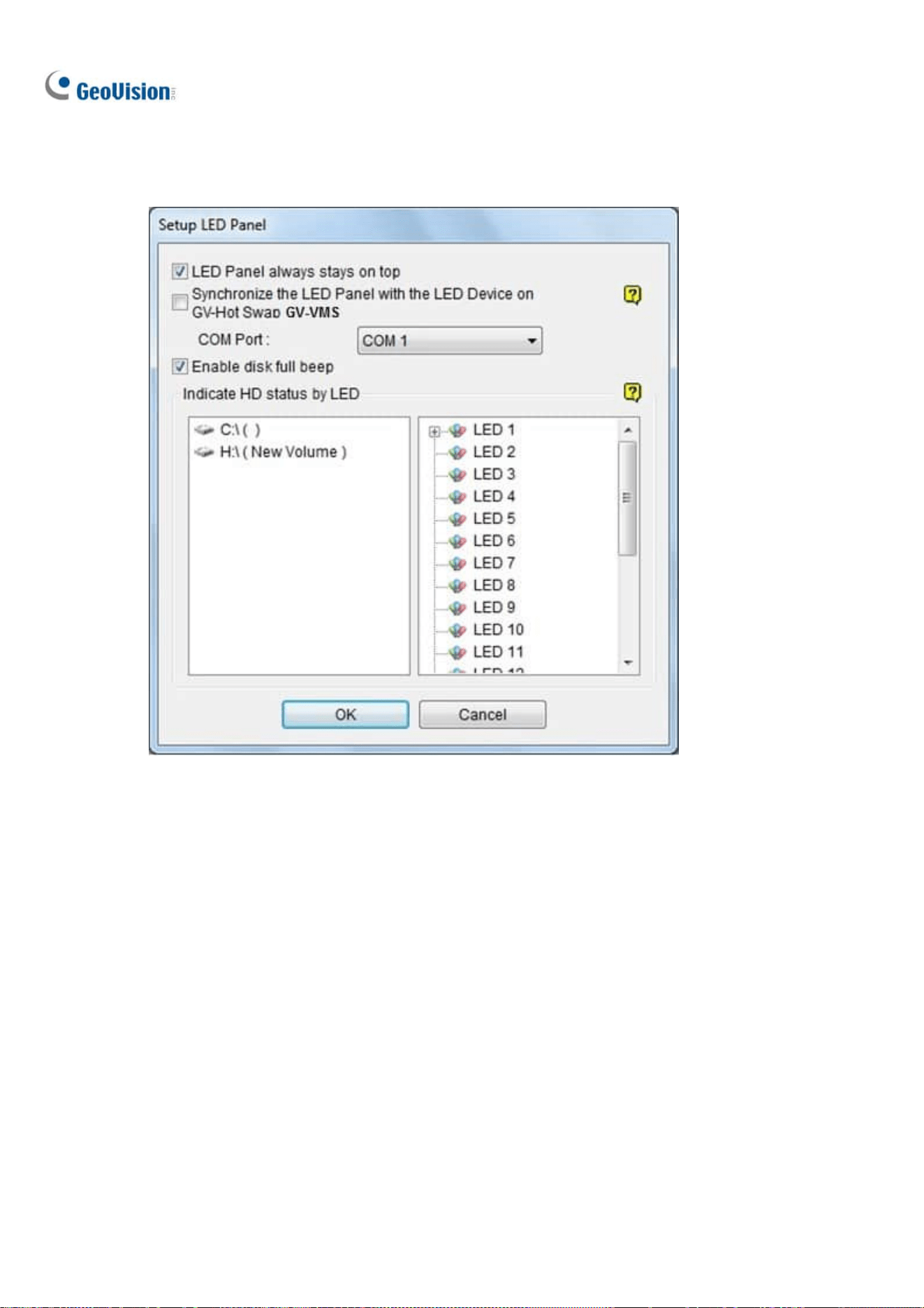
324
1. Click Tools on the menu bar on the Media Man Tools window, and select Setup LED Panel. This
dialog box appears.
Figure 9-55
LED Panel always stays on top: Makes the LED panel stay on top of other windows when
the Media Man Tools window is minimized.
Synchronize the LED Panel with the LED Device on GV-Hot Swap VMS: For GV-Hot
Swap VMS System only. If enabled, the LED device installed on the front panel of the
GV-Hot Swap VMS System will synchronize with the LED panel on the screen.
Enable disk full beep: When the hard disk drive is full, the system makes the beeping
sound. Note this function only works when the motherboard is equipped or installed with a
PC speaker.
2. By default, only the hard disk drive that stores video and audio files will be assigned to LED. If you
want to re-assign the hard disk drive or assign other drives to LEDs, freely move the hard disk
drive to the desired LED on the tree.
3. Click OK to apply the settings, and minimize the Media Man Tools window to display the LED
panel on the screen.

Useful Utilities
325
9
4. If you want to return to the Media Man Tools window, right-click the LED panel and select Switch
to the setup window.
Note:
1. Because the LEDs are designed to indicate the video and audio files are being written or read, it
is not recommended to assign the HDDs that store log files to the LEDs.
2. If the HDD that stores log files is assigned to a LED and its LED turns red, make sure the log
files are not being written before you remove it. Otherwise, the log files might be lost during the
removal. The default location for data storage is D:\Record\<camxx or audxx folder> for
recorded files, D:\CameraDBs\ for event database files, and C:\GV-VMS\Database for system
logs.
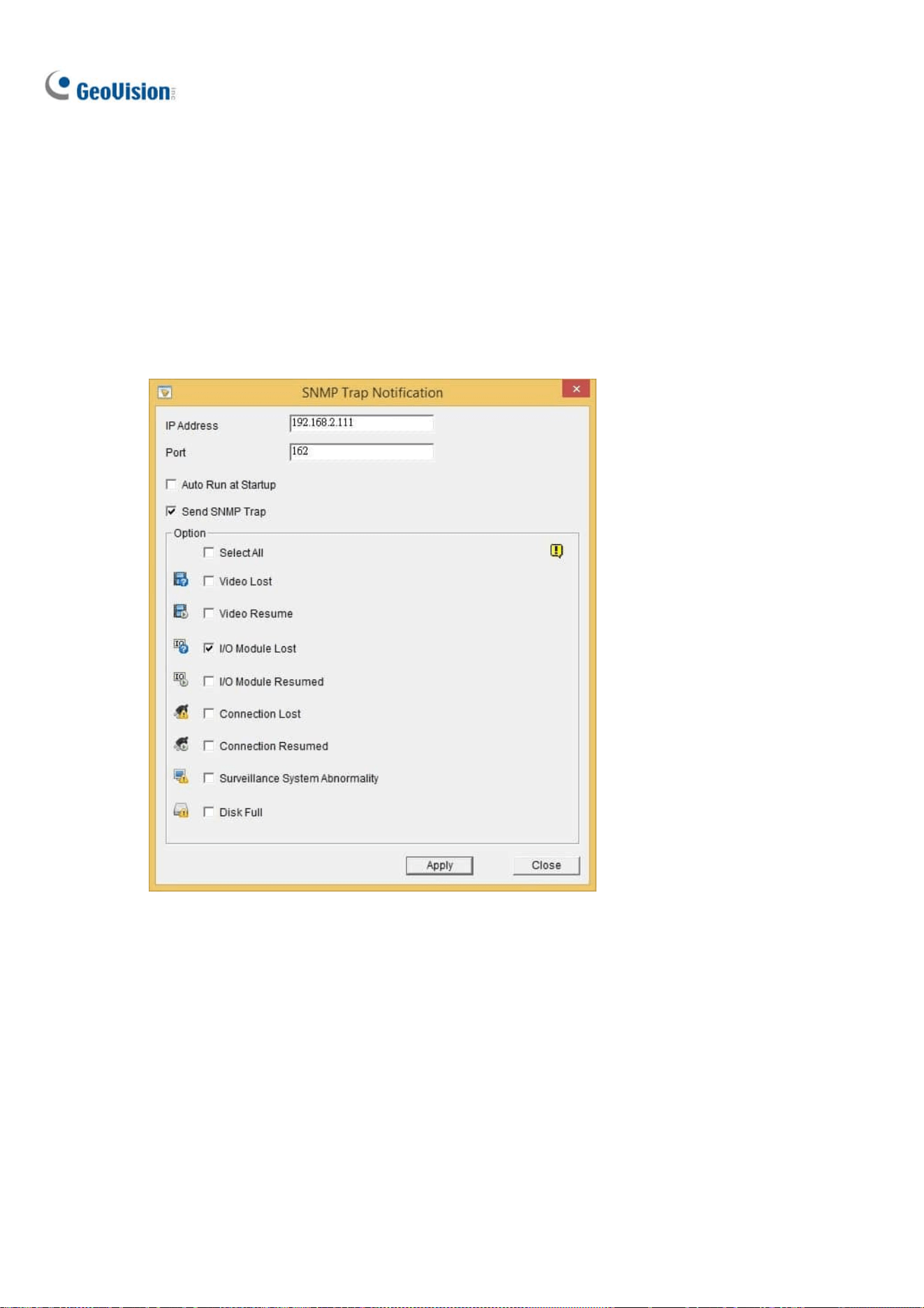
326
9.10 Alert Notifications through SNMP Protocol
You can send alert notifications to SNMP-compatible software by using the SNMP Trap Notification
utility.
1. Click Windows’ Start > All Programs > the GV-VMS folder > SNMPTrapNotification.exe. This
dialog box appears.
Figure 9-56
2. Type the IP address of the software that will be receiving the alert notification, and modify the
Port if needed.
3. To run SNMP Trap Notification upon system startup, select Auto Run at Startup.
4. Select Send SNMP Trap to enable the function.
5. Under Option, select the types of notifications you want to send to the software.
6. Click Apply.

Useful Utilities
327
9
9.11 Local and Remote Backup
GV-VMS can back up recorded files to any connected hard disk drives or GV-Backup Center over the
Internet. A copy of recorded files will automatically be backed up to the assigned path or GV-Backup
Center.
Note: You can only choose either Local Backup or Remote Backup (with GV-Backup Center). The
two backup methods can not be applied at the same time.
9.11.1 Remote Backup
To back up with GV-Backup Center, see 3.3 Connecting GV-DVR / NVR / VMS in GV-Backup Center
User’s Manual.
9.11.2 Local Backup
To connect to a hard disk drive, follow the steps below:
1. Click Home
> Toolbar > Network < Backup Center. The Backup Server dialog
box appears.
Figure 9-57
2. Select Local Backup in the left pane.
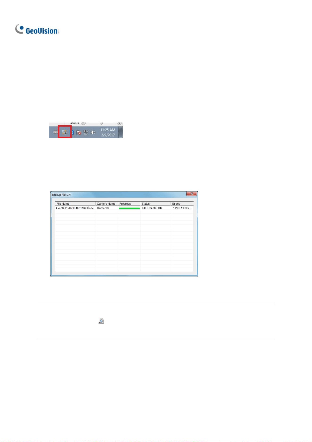
328
3. Specify in which hard drive you want to back up your files. If you assign multiple hard drives,
when the first hard drive is full, the files will be backed up to the second hard drive.
4. For Advanced Settings, see the later section for details.
5. To configure file backup schedule and transfer time, see File Transfer Setting for Local Backup
later in this chapter.
6. Select your desired storage path and select Connect to back up files.
7. On the Windows taskbar, right-click on the Geo Backup Client icon. Three options are available:
Figure 9-58
Status: “Connected” indicates that Local Backup is successfully activated.
Backup Status: indicates the status of file backup.
Playback: open ViewLog player for playback.
Figure 9-59
Note:
1. You can also click on the first setting page of Local Backup to open ViewLog player.
2. Be sure to assign different Local Backup storage paths from those of GV-VMS.

Useful Utilities
329
9
9.11.3 Advanced Settings
9.11.3.1 Advanced Settings for Local Backup
Figure 9-60
Minimum Recycle Threshold: Specify a minimum free space of your local storage for file
recycling.
Keep Days: Specify the number of days to keep the download files at the local hard drive.
Compact Video Files Before Backup: Compact the recorded video files before backing up.
If the recorded video is compressed with H.265 or H.264 codec, it will be compacted into key
frames only.
If the recorded video is compressed with MJPEG codec, you can use the Reserved Frames
(MJPEG) option to specify the number of frames.
Limit Bandwidth xx KB/Sec: Specify a bandwidth limit when uploading files.
Copy Viewlog to backup drives: Copy the ViewLog player to the assigned backup drives.
Delete these source files after the backup is complete: Delete the recorded files in GV-VMS
after the files are successfully backed up.

330
9.11.3.2 File Transfer Settings for Local Backup
The File Transfer Setting allows you to specify the recordings to back up and transfer time.
In this setting dialog box, you can define the following backup rules:
The day of recordings to be transferred.
The time period of recordings to be transferred.
The type of recordings to be transferred, including motion detection, I/O trigger or all types of
events.
The time to back up the files.
Figure 9-61
[Working Days] Define up to 10 backup rules to specify which recordings, including which type, which
time period and on which working days they were recorded to be transferred to the assigned hard disk
drive.
1. Select the day, including Monday to Sunday.
2. Click the arrow button before Time Span and select Modify.
Figure 9-62

Useful Utilities
331
9
3. In this dialog box, select the Camera that you want to back up its recordings, specify Time Span
in which time period of recordings to be transferred, and select Events that you want to back up
all event files, Motion or I/O trigger events only.
Figure 9-63
4. Click OK. The backup settings are created.
5. To define another backup rule, click the
button. A new Time Span is created.
Figure 9-64
6. Click the arrow button, select Modify and follow the step 3 to define the backup rule.
[Holidays] Define up to 10 backup rules for non-working days, which include which non-working day,
which camera and which type of recording to be transferred to the assigned hard disk drive. For how to
set up a rule, see the instructions in the above [Working Days].
[Transfer Time] Define the daily time, from 00:00 to 23:59:59, to back up the files from the hosts to the
assigned hard disk drive.

332
9.12 Report Generator
Report Generator is a useful utility that allows users to generate daily and/or weekly reports, in MDB or
HTML format, for the recording data of GV-VMS without requiring additional installation.
For details, see Report Generator User’s Guide
.
9.13 GV-Cloud Center
You can search events of GV-VMS with the cloud-based service, GV-Cloud Center. Using myGVcloud
NotifyApp, you can receive notifications, look up events, access live view and play back recordings
from any iOS or Android mobile devices. Without installing any software, you can also log onto
GV-Cloud Center Portal from a Web browser on any PC to access GV-Cloud Center for event search
and playback. For details, see GV-Cloud Center User’s Manual
.
Figure 9-65

333
Chapter 10
Point-Of-Sale (POS) Application ................. 334
10.1 Setting up Text Overlay ............................................................... 335
10.2 Filtering Transactions for a Product Item ............................. 336
10.3 Triggering Transaction Alarms .................................................. 338
10.4 Mapping Codepage ........................................................................ 340
10.5 Coloring Transactions of a Product Item ............................... 341
10.6 Displaying the Receipt Details of a Transaction ................. 344
10.7 Filtering Transactions by a Keyword....................................... 350
10.8 Searching for POS Events ........................................................... 353

334
Point-Of-Sale (POS) Application
A POS device can be integrated to GV-VMS with transaction data overlaid on video channels.
Transaction alerts can be triggered to notify you of transaction events. Video searches can be
performed based on a specific transaction item or a specified time period.
GeoVision provides three POS integration solutions to meet a variety of needs.
1. Direct POS Integration
2. GV-Data Capture Box Integration
3. Graphic Mode POS Integration
Please check the flowchart to find out which solution is suitable for you.
CHAPTER
10

Point-of-Sale (POS) Application
335
10
10.1 Setting up Text Overlay
To change the text font and position of the transaction data on the live view and recorded files, click the
Text Setup button on the POS Server Setup dialog box (Home > Toolbar > Configure > System
Configure > Accessories > POS Device Setup > select one POS device on the list > click the Modify
button).
Figure 10-1
[Text]
◼ Print on video file: Displays POS data on the recorded video file.
◼ Print on screen: Displays POS data on the transaction scene.
◼ Alignment: Select the position of text overlay on the screen.
[Clean Time]
◼ Clean time: Specify the amount of time in seconds after which GV-VMS has not received the
transaction data from the POS device, i.e. the cashier stops entering the transaction data. The
already-displayed POS data will be hidden from the live view.
◼ Transaction end dwell time: Specify the amount of time in seconds that POS data stays on
the live view before the next transaction.
[Set Font] Click the Set Font button to set up the font for POS data.

336
10.2 Filtering Transactions for a Product Item
POS Field Filter allows you to create an independent column for a transaction item in System Log. The
feature filters the transactions, and highlight the price of the item under the created column.
For this example, the transaction item is “Golden Pineapple” which transaction data stands out in the
System Log to attract your attention.
Figure 10-2
To set up the function, follow the steps below:
1. On the POS Server Setup dialog box, select a POS device, and select Capture Data Setting. The
POS Capture Data Setting dialog box appears.
Figure 10-3

Point-of-Sale (POS) Application
337
10
2. Select a POS device from the drop-down list for setup.
3. Click the New button and select Caption Data. This dialog box appears.
Figure 10-4
[Key Word] Type a keyword matching exactly a transaction item in the receipt. The field is case
sensitive.
[Capture Data Type] Select the type of data followed by the specific transaction item: Numeric,
Currency or Text. If the transaction item is followed by a price amount, select Numeric or
Currency. If it is followed by alphabets, select Text. Any defined amount or text after the keyword
will be brought out.
◼ With Comma: If there are commas in a price amount, e.g. $1,000, select the option.
◼ With Decimal Sign: If there are decimal signs in a price amount, e.g. $10.5, select the option.
◼ With Space: The option is only available when you select Text. If there is space among
letters, select the option.
[MDB File Entry Name] Name the file to store the data.
4. Click OK.
5. Open the POS Table (ViewLog > Toolbar > Tools > System Log) to see the filtering results.

338
10.3 Triggering Transaction Alarms
When the abnormal transaction amount of an item occurs, this function can automatically activate the
output device and send out E-Mail alerts. To set up this function, follow these steps:
1. Follow the steps in Filtering Transactions for a Product Item earlier in this chapter to define a
transaction item first. Note that for this alarm function, a space between letters for the Keyword is
not allowed.
2. Click the Loss Prevention Setting button. This dialog box appears.
Figure 10-5
[Alarm Conditions] Define the price range for an alarm condition. For this example, when the
price amount in a transaction is great than (>) than 2 dollars, the assigned alarm output and e-mail
alert will be activated.
[Advanced button] See Step 3 below to define the alarm frequency.
[Alarm Output] Assign an installed output module. When the defined alarm condition is met, the
output alarm will be triggered.
[Alert Message] Type an alert message (the space between letters is not allowed). When the
defined alarm condition is met, the e-mail alert will be sent. To enable e-mail notifications, see
Setting up E-mail Notifications in Chapter 1. And the alert message will also be noted in the System
Log.

Point-of-Sale (POS) Application
339
10
3. To eliminate false alarms, configure alarm frequency.
Figure 10-6
◼ Frequency Condition: Enable to set up the number of event occurrences within a time period
to trigger the alarm.
Number of Occurrences: Specify the number of event occurrences.
Time Frame: Select one of the time periods: one hour, 12 hours, one day, one week or
one month.
4. Open the POS Table (ViewLog > Toolbar > Tools > System Log). The transactions met the
defined alarm conditions will be marked with “unusual transaction” event in the System Log.
Figure 10-7

340
10.4 Mapping Codepage
This feature is to support the display of special characters and symbols. When transaction text
incorrectly appears on the screen, a wrong character code may be used. To change a character code,
follow the steps below.
Note: When you cannot find a proper “Script” in the Set Font option (Figure 10-1), you may use the
Codepage feature to fix the display issue of transaction text.
1. In the Device dialog box, select Use Codepage Mapping and select a character code from the
drop-down list.
Figure 10-8
2. To verify the character code you selected, click the […] button to preview its codepage.
Figure 10-9
3. In the From field, select one symbol or character that are not displayed correctly. In this example,
you can see its previous character code (From side: Ox9C) has been transferred to the default
equivalent (To side: OxA3).
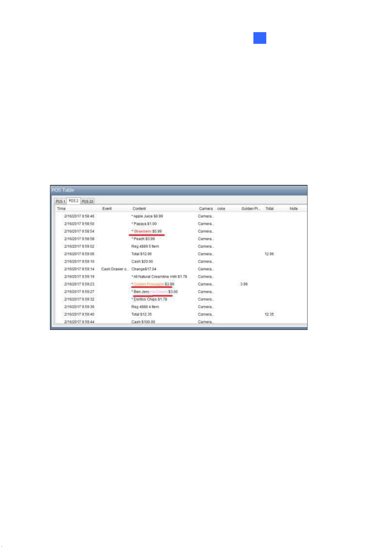
Point-of-Sale (POS) Application
341
10
10.5 Coloring Transactions of a Product Item
You can highlight a desired transaction item in any color. When the transaction item is identified, its text
will have an outstanding color than others on the live view, and the alarm and e-mail alerts can be
triggered at the same time. For example, if the liquor is prohibited for sale in the midnight, a seller can
use this feature to prevent from any unintentional sale.
The identification will be recorded in the System Log for later retrieval as well. In this example, the
transaction item “Strawberry” is colored red, “Golden Pineapple” is orange, and “Ice Cream” is pink
whenever these transaction items appear.
Figure 10-10

342
To configure the coloring feature, follow the steps below:
1. On the POS Server Setup dialog box, select Capture Data Setting. The POS Capture Data
Setting dialog box appears.
Figure 10-11
2. Click New and select Color Keyword. This dialog box appears.
Figure 10-12
[Key Word] Type the keyword to be identified in the transactions. The field is case sensitive.
[Color] Select a color to show on the keyword.
[Only work between] Specify the time period of transactions to identify the keyword.
Note: You can set up to 32 keywords for identification.

Point-of-Sale (POS) Application
343
10
3. To trigger an alarm when the keyword is detected during the transactions, click the Loss
Prevention Setting button. This dialog box appears.
Figure 10-13
◼ Alarm Conditions: Enable the alarm when the defined text is detected. To configure alarm
frequency, click the Advanced button. For details, see Step 3, Triggering Transaction Alarms
earlier in this chapter.
◼ Alarm Output: Assign an installed output module. When the defined alarm condition is met,
the output alarm will be triggered.
◼ Alert Message: Type an alert message. When the defined alarm condition is met, the e-mail
alert will be sent. To enable e-mail notifications, see Setting up E-mail Notifications in Chapter 1.
4. Click OK.
When the keyword is identified in the transactions, the identification appears not only on the live view,
but also are recorded in the System Log (ViewLog > Toolbar > Tools > System Log > POS Table).

344
10.6 Displaying Receipt Details of a
Transaction
You can find out receipt details of a single transaction. You will know the amount of the transaction,
as well as the total number and total amount of all transactions during a defined period of time.
All the transaction contents related to the
single transaction
Number of transactions during
the defined period of time
Amount of the single
transaction
Total amount of transactions
during the defined period of time
A single transaction
Figure 10-14
To have the feature, you need to define the format of how the amount of a transaction is shown and
how a transaction ends on the receipt. Follow the 3 steps below to complete the settings:
⚫ Step 1: Defining the Amount of a Transaction Shown on the Receipt
⚫ Step 2: Define How a Transaction Ends on the Receipt
⚫ Step 3: Displaying Receipt Details of a Transaction

Point-of-Sale (POS) Application
345
10
Step1: Defining the Amount of a Transaction Shown on the Receipt
1. On the POS Server Setup dialog box, select a desired POS device, and select Capture Data
Setting. The POS Capture Data Setting dialog box appears.
2. Click the New button. This dialog box appears.
Figure 10-15
3. Take the following receipt as an example.
Figure 10-16

346
a. Type the keyword related to the amount of a transaction. In this example, the keyword is
“Total” which is a prefix in the amount and appears in every receipt. Note the field is case
sensitive.
b. Under Capture Data Type, define if the total amount is attached with a currency symbol. In
this example, select Currency because the currency symbol $ is used.
c. Select With Comma if there are commas in the total amount. Select With Decimal Sign if
there are decimal signs in the total amount. In this example of “Total $12.35”, select With
Decimal Sign.
4. Select Transaction Amount, and click OK.
Step 2: Defining How a Transaction Ends on the Receipt
5. On the POS Server Setup dialog box, select the specific POS device, and select Filter Setting.
The Filter Setting dialog box appears.
Figure 10-17

Point-of-Sale (POS) Application
347
10
6. Click the New button. This dialog box appears.
Figure 10-18
a. Under Select Sample, select the type of printer attached to the POS device, or the
GeoVision program installed in the POS device.
b. Under Filter Name, name the filtering criteria. In this example, we will define how a
transaction ends on a receipt, so naming it as “End of Transaction”.
7. Click the Add button. The Filter Name appears in the list.
8. Select the created filter name and click the Modify button. This dialog box appears.
Figure 10-19

348
9. Click the New button. This dialog box appears.
Figure 10-20
10. Type the keyword indicating the end of a transaction, and add comma (,) between every letter. In
this example, the keyword is “Change” which appears at the end of every transaction, so type
C,h,a,n,g.e.
Figure 10-21
11. Under Action, select Stop Transaction.
12. Click OK several times to return to the POS Server Setup dialog box.
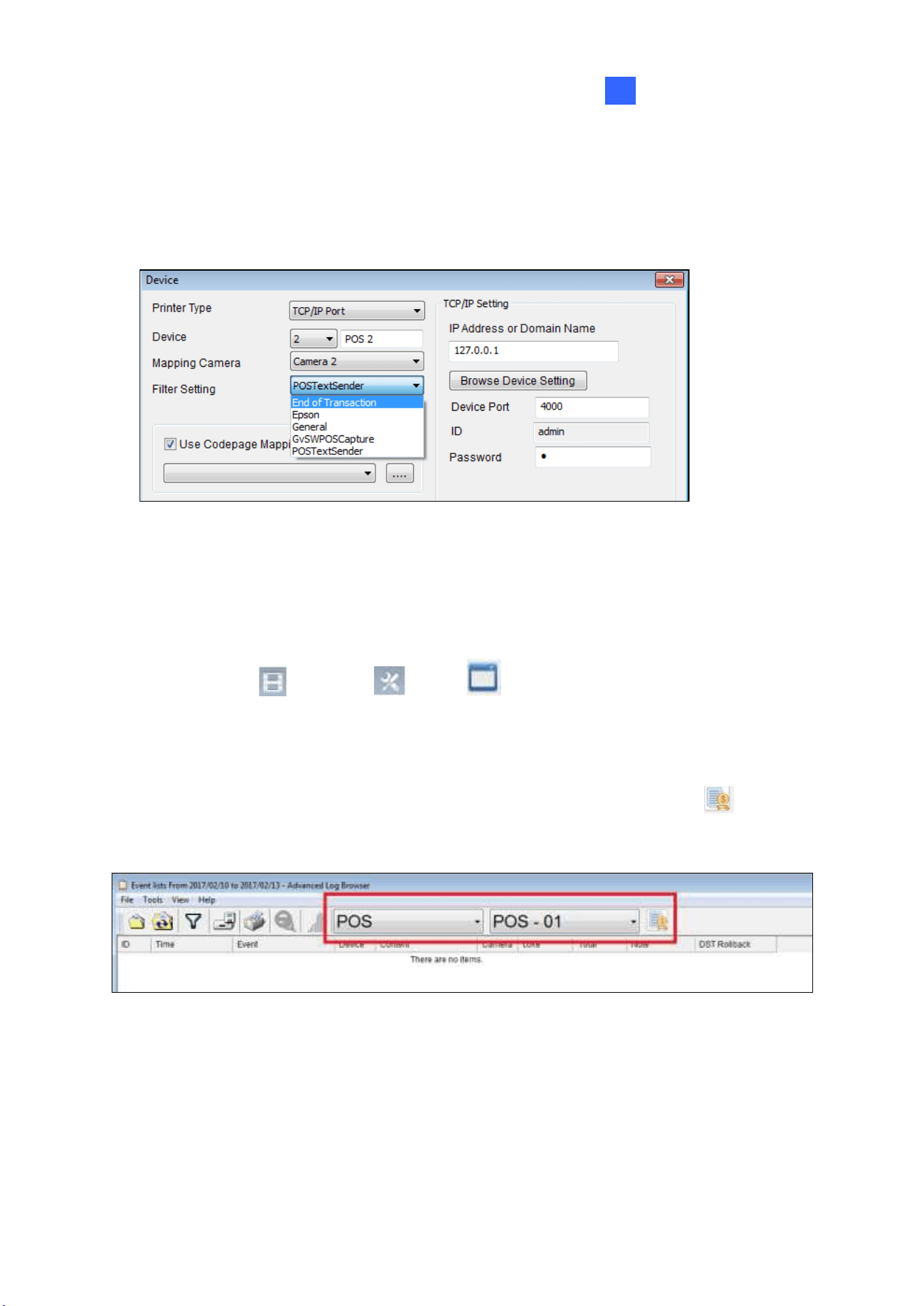
Point-of-Sale (POS) Application
349
10
13. Select the POS device in the list applied for the filter setting, and click the Modify button. The
Device dialog box appears.
14. Under Filter Setting, select the filter setting you set up for the end of a transaction. In this example,
its “End of Transaction”.
Figure 10-22
15. Click OK.
Step 3: Displaying Receipt Details of a Transaction
16. Select ViewLog > Toolbar > Tools > System Log > Advanced. The Open
Database dialog box appears.
17. Define a period of time to retreive the POS data.
18. From the left side of toolbar, select POS data, select which POS device, and click to have a
list of transactions during the defined period of time.
Figure 10-23
19. When you click a transaction on the List, its related receipt content will be displayed.

350
10.7 Filtering Transactions by a Keyword
You can filter transactions by a keyword to have the following functions: to start a new line after the
keyword, to remove unwanted text before the keyword, to replace a keyword with another, and/or to be
noted as Event, such as Cash Drawer Open, in the System Log when the keyword appears.
For example, we define “Change” as the keyword, and specify it as “Cash Drawer Open” event.
Whenever “Change” appears on the receipt, in the System Log, you will see not only the details of the
transaction, but also an event “Cash Drawer Open” recorded.
Figure 10-24

Point-of-Sale (POS) Application
351
10
To configure the function, follow the steps below:
1. To open the following dialog box, follow Step 5 to 8 in Step 2: Defining How a Transaction Ends
on the Receipt, 10.6 Displaying Receipt Details of a Transaction.
Figure 10-25
2. Type the keyword and add comma (,) between every letter. In this example, the keyword is
“Change”, so type C,h,a,n,g.e.
3. If the keyword has a random prefix, select Use Random Word, and type the symbol (*) before
the keyword, e.g. *,C,h,a,n,g.e.
4. If you want the text to start a new line whenever the keyword appears, select Command is
change line.
5. If you want to remove garbled text before the keyword, type the number of characters you want to
remove in Cut Length.
6. If you want to replace the keyword with another, select Use Replace and type a desired word.
7. You can define an event to show in the System Log: Alert, Cash Drawer Open, Cash Drawer
Close, Start Transaction, Stop Transaction, or Valid Transaction.
8. Click OK several times to return to the POS Server Setup dialog box.
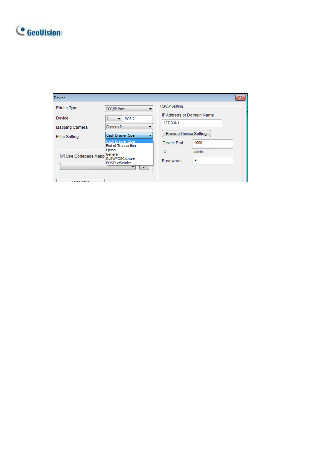
352
9. Select the POS device in the list applied for the filter setting, and click the Modify button. The
Device dialog box appears.
10. Under Filter Setting, select the filter setting you set up before. In this example, it is Cash Drawer
Open.
Figure 10-26
11. Click OK.
12. Open the System Log (ViewLog > Toolbar > Tools > System Log > POS Table) to view the
filtering results.

Point-of-Sale (POS) Application
353
10
10.8 Searching for POS Events
With the POS Search function, you can instantly search for and play back POS events from the
ViewLog. To access this function, click ViewLog > Toolbar > Tools > POS Search. This
window appears.
1
3
8
7
4
2
5
6
9
Figure 10-27
No.
Name
Description
1
Playback Window
Displays the recording of the POS event or content selected. Right-click
on the window to have the options of Play Mode, Render and Tools
2
Transaction Window
Displays all POS transactions viewed while playing back on the Playback
Window.
3
Exit
Click to close Quick Search screen
4
Playback Panel
Includes Play, Pause, Previous 10 frames, Next 10 frames and End
buttons, as well as Time Period buttons to jump to 1 second, 10 seconds,
1 minute, 10 minutes and/or 1 hour later or earlier.

354
5
Expand /
Shrink Dialog
Select Expand/Shrink Dialog to display the Transaction window or
select Advanced Search to display the Advanced Search panel.
6
Find Condition
Click Find Condition to search for specific keywords and/or a type of
POS transaction event forward or backward, starting from a date and
time set. Use the Find Previous and Find Next buttons to jump
from one search result to another.
7
Advanced Search
Panel
See 6.1.1 Advanced Search Settings later.
8
Search Results
Displays the search results by Advanced Search.
9
320<->640
Click to switch between 640 x 480 and 320 x 240 display.
Advanced Search Panel
To search for POS events with detailed criteria, click Expand / Shrink Dialog on the POS Search
windo and select Advanced Search. The Advanced Search Panel appears.
1. Select the Start / End Dates and Start / End Times from the respective drop-down lists to
specify the desired time period of your POS search.
2. Select the POS devices you want to search for in the POS Device drop-down list.
3. Optionally select POS Event to search for a type POS transaction event.
4. Optionally select Find Text to type a keyword you want to search for.
5. After the desired conditions are set, click Search . The search results will be displayed at the
left of the panel.