Loading ...
Loading ...
Loading ...

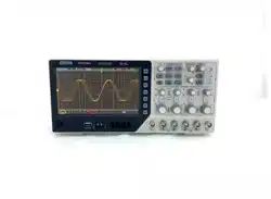
DPO6000, MPO6000 Series Digital Fluorescent Oscilloscope Product Manual V1.3
63
Protocol decoding
Users can easily find errors, debug hardware, and accelerate development progress
through protocol analysis. DPO6000 / MPO6000 series machines provide decoding of
5 common protocols, including UART, LIN, CAN, IIC and SPI.
Note: Only when the user correctly configures the protocol trigger setting parameters
can the correct decoding result be obtained.
Decoding mode
The decoding function is only available when the protocol is triggered. Turn on the de-
coding switch. At this time, the magenta serial decoding cursor appears on the left side
of the oscilloscope (the default is at the bottom of the screen). The user can change the
position of the label by selecting the label position menu The decoded position acquisi-
tion waveform has a better display position for users to analyze the decoded data.
Table mode
The table function can only be used when the protocol is triggered. When the table
mode is enabled, the oscilloscope does not perform waveform data acquisition and
display when the oscilloscope is running in the table mode. It only displays the correct
protocol decoded data. The decoded data is transmitted to the screen in real time.
When the oscilloscope is running in table mode, only F1, F2, F3, RUN / Stop soft keys
can be used, and other keys cannot be used. If the user needs to set other parameters
of the serial port, he needs to exit table mode. After the user pauses, the decoded data
can be exported for analysis.
Mathematics
Addition
The waveform values of data source 1 and data source 2 are added point by point and
the result is displayed.
Steps:
1. Press the Math button on the front panel to enter the MATH function menu. Turn the
multi-function knob V0 to select "+" for addition operation.
2. Press the [Data Source 1] and [Data Source 2] soft keys and turn the multi-function
knob V0 to select the data source. 4 analog channels can be used as data sources.
The resulting math waveform is displayed on the screen and labeled "M".
3. Operation waveform settings:
Loading ...
Loading ...
Loading ...