
DPO6000, MPO6000 Series
Digital Fluorescent Oscilloscope
Product Manual
V 1.3

DPO6000, MPO6000 Series Digital Fluorescent Oscilloscope Product Manual V1.3
Copyright Statement
Copyright
Qingdao Hantek Electronic Co., Ltd.
Statement
Qingdao Hantek Electronic Co., Ltd. reserves the right to amend this document without
prior notice. Qingdao Hantek Electronic Co., Ltd. promises that the information provid-
ed is correct and reliable, but does not guarantee that this document is infallible. Please
make sure that the specifications of relevant technical documents used are the latest
and valid version yourself before using this product. If you require the cooperation of
products, patents or works of a third party when your company using the documents or
products of Qingdao Hantek Electronic Co., Ltd., your company shall be responsible for
obtaining the consent and authorization of the third party. The aforesaid consent and
authorization is not the responsibility of our company to guarantee.

DPO6000, MPO6000 Series Digital Fluorescent Oscilloscope Product Manual V1.3
Technical Support
If you have any question or ambiguity in the process of using products of Qingdao
Hantek Electronic Co., Ltd., you can get the service and support through the following
ways:
A: Please contact the local dealer of Qingdao Hantek Electronic Co., Ltd.;
B: Please contact the local office directly under Qingdao Hantek Electronic Co., Ltd;
C: Please contact the headquarters of Qingdao Hantek Electronic Co., Ltd.
Contact Method of our company:
Qingdao Hantek Electronic Co., Ltd.
http://www.hantek.com/en/index.html
Address: 35# Building No.780 Baoyuan Road, High-tech District, Qingdao China
Zip Code: 266114
Telephone: 0532-88705792
Fax: 0532-88705691
Email: [email protected]om
Technical Support:
Telephone: 0532-88703687
Email: [email protected]

1
Summary of general safety matters
General Safety Summary
Read the following safety precautions carefully to avoid injury and prevent damage to
this product or any product connected to this product. To avoid possible danger, be sure
to use this product as specified.
Avoid fire and personal injury.
Only professionally authorized personnel should perform repairs.
Use the correct power cord.
Use only the power cord specified for this product in your country.
Connect and disconnect properly.
Before connecting the probe to the circuit under test, please connect the probe to the
oscilloscope; before disconnecting the probe from the oscilloscope, disconnect the
probe from the circuit under test.
Ground the product.
To avoid electric shock, the product is grounded through the grounding conductor of the
power cord. The grounding conductor must be connected to ground. Before connecting
the input or output of the product, be sure to ground the product properly.
Connect the probe properly.
If using a probe, the probe ground must be connected to the ground. Do not connect
the probe ground lead to high voltage, otherwise, dangerous voltage may be generated
on the oscilloscope and probe connector, control equipment or other surfaces, which
may cause injury to the operator.
View all terminal ratings.
To avoid fire or the impact of excessive current, check all ratings and markings on the
product. Please consult the product manual for details on ratings before connecting the
product.
Use proper overvoltage protection.
Make sure that no over voltages (such as those caused by lightning) reach the product.
Otherwise, the operator may be exposed to electric shock.
Do not open the cover.
Do not operate the product with the cover or panel open.
Maintain proper ventilation.

DPO6000, MPO6000 Series Digital Fluorescent Oscilloscope Product Manual V1.3
2
Poor ventilation will increase the temperature of the instrument and cause damage to
the instrument. Good ventilation should be maintained during use, and the vents and
fans should be checked regularly.
Use a suitable fuse.
Only use fuses specified for this product.
Avoid exposed circuits.
Do not touch exposed connectors and components after power is turned on.
Do not operate the product if you suspect it is malfunctioning.
If the user suspects that this product has been damaged, have it inspected by qualified
service personnel.
Do not operate in a humid environment.
To avoid the danger of short circuit or electric shock inside the instrument, do not oper-
ate the instrument in a humid environment.
Do not operate in a flammable or explosive environment.
To avoid damage to the instrument or personal injury, do not operate the instrument in a
flammable or explosive environment.
Keep the surface of the product clean and dry.
To prevent dust or moisture in the air from affecting the performance of the instrument,
keep the product surface clean and dry.
Anti-static protection.
Static electricity can cause damage to the instrument. Test in an anti-static area when-
ever possible. Before connecting the cable to the instrument, ground its inner and outer
conductors briefly to discharge static electricity.
Pay attention to handling safety.
In order to avoid the instrument falling down during transportation, which may cause
damage to the buttons, knobs, or interfaces on the instrument panel, please pay atten-
tion to transportation safety.
Safety terms and symbols
Product terminology. The following terms may appear on the product:
DANGER
It indicates that if you do this, you may cause immediate damage to the user.
WARNING
DPO6000, MPO6000 Series Digital Fluorescent Oscilloscope Product Manual V1.3
3
It indicates that the user may not immediately harm the user if they do this.
CAUTION
It indicates that the user may cause damage to this product or other property if this
operation is performed.
Product symbol. The following symbols may appear on the product:
Safety Warning Protective Test Ground Shell Earth Terminal
Measurement category
Measurement category DPO6000 / MPO6000 series digital oscilloscopes can perform
measurement under measurement category I.
WARNING
This oscilloscope is only allowed to be used in the specified measurement
category.
Measurement category definition
Measurement category I
Refers to measurements on circuits that are not directly connected to the mains. For
example, make measurements on circuits that are not derived from a main power
source, especially those that are protected (internal). In the latter case, the transient
stress changes. Therefore, users should understand the instantaneous ability of the
device.
Measurement category II
Refers to measurements made on circuits directly connected to low-voltage equipment.
For example, make measurements on home appliances, portable tools, and similar de-
vices.
Measurement category III
Refers to measurements in construction equipment. For example, power distribution
boards, circuit breakers, wiring (including cables, bus bars, junction boxes, switches,
sockets) in fixed equipment, and equipment for industrial use and certain other equip-
ment (for example, fixed motors permanently connected to fixed equipment) Take
measurements.
Measurement category IV
DPO6000, MPO6000 Series Digital Fluorescent Oscilloscope Product Manual V1.3
4
Refers to measurement at the source of the low-voltage equipment. Examples are elec-
tricity meters, measurements on major overcurrent protection devices, and measure-
ments on pulse control units.
Ventilation requirements
The oscilloscope is forcedly cooled by a fan. Ensure that the intake and exhaust areas
are free of obstructions and free-flowing air. To ensure adequate ventilation, when using
the oscilloscope in a workbench or rack, ensure that there is a gap of at least 10 cm on
its sides, above, and behind.
WARNING
Poor ventilation will increase the temperature of the instrument and cause
damage to the instrument. Good ventilation should be maintained during use. Reg-
ularly check the vents and fans.
Working environment
Temperature
During operation: 0℃ to +50℃
Non-operating: -40℃ to +70℃
Humidity
0℃ to +30℃: 95% relative humidity
+30℃ to +40℃: 75% relative humidity +40℃ to +50℃: 45% relative humidity
WARNING
To avoid the danger of short circuit or electric shock inside the instrument,
do not operate the instrument in a humid environment.
Altitude
When operating: below 3000 meters
Non-operating: below 15000 meters
Daily maintenance and cleaning
Daily maintenance
When storing or placing the oscilloscope, do not expose the LCD monitor to direct sun-
light for a long time.
DPO6000, MPO6000 Series Digital Fluorescent Oscilloscope Product Manual V1.3
5
Clean
According to the requirements of operating conditions, check the oscilloscope and
probe frequently. Please clean the outer surface of the instrument according to the fol-
lowing steps:
Use a lint-free cloth to remove dust from the outside of the oscilloscope and probe. Be
careful not to scratch the smooth display filter.
Clean the oscilloscope with a soft cloth dampened with water. For more thorough
cleaning, use 75% isopropyl alcohol in water.
CAUTION
To avoid damaging the surface of the oscilloscope or probe, do not use any
corrosive or chemical cleaning agents.
Equipment recycling
Production of this equipment requires the extraction and use of natural resources. If
this product is not disposed of properly, some of the substances contained in the device
may be harmful to the environment or human health. To avoid release of harmful sub-
stances into the environment and reduce the use of natural resources, it is recom-
mended that this product be recycled by appropriate methods to ensure that most ma-
terials can be reused correctly.
Introduction to DPO6000 / MPO6000 Series
Digital Phosphor Oscilloscope
DPO6000 / MPO6000 series oscilloscopes have extremely high memory depth, ultra-
wide dynamic range, good display effect, and high waveform capture rate and up to 16
trigger functions, 5 serial decoding functions, which are communication, aerospace, na-
tional defense, embedded Instrumentation in many industries and fields such as em-
bedded systems, computers, research and education.
Main feature:
★The real-time sampling rate of the analog channel is 1GSa/s, the standard configura-
tion is 64Mpts, and the maximum memory depth is 128Mpts (6000EDU series).
★Digital channel real-time sampling rate 1GSa/s
CAUTION
To avoid damaging the oscilloscope or probe, do not place it in mist, liquid
or solvent.

DPO6000, MPO6000 Series Digital Fluorescent Oscilloscope Product Manual V1.3
6
★200MHz, 100MHz and 80MHz analog channel bandwidths are available
★4 analog channels, 16 (4*4) digital channels (MPO6000 series; DPO6000 series can
be upgraded to use digital channels by purchasing LP104 digital probe)
★Two / three-channel signal source (MPO6000EDU is three channels) Built-in 13 kinds
of waveforms, 4 groups of arbitrary waveforms, 200MSa/s sampling rate, 8Kpts wave-
form length
★60,000 wfms/s (point display) / 400,000 wfms/s (point display fast acquisition mode)
waveform capture rate
★Segmented acquisition function, supports up to 80,000 segments
★256-level grayscale display
★Ultra-low noise floor, ultra-wide vertical dynamic range from 500uV/div to 10V/div
★7-inch WVGA (800*480) TFT widescreen, vivid colors, low power consumption, and
long life
★7-inch capacitive touch screen, support multi-touch
★Adjustable waveform brightness and display brightness
★Up to 16 trigger functions, including 5 protocol triggers
★Provide 5 kinds of serial decoding options
★42 kinds of waveform parameter automatic measurement (statistic function optional)
★5-digit digital voltmeter and 6-digit hardware frequency meter function
★Bode plot function (optional signal source function)
★Event search function
★Dual window display function
★Built-in FFT function
★Multiple waveform mathematical operation function
★Standard ports: USB Device, USB Host, LAN
★WIFI (6000EDU series)
★Optional interface: HDMI, UART, AUX
★Pass/fail, trigger output (standard for MPO6000EDU, optional for non-MPO6000EDU)
★Meets LXI CORE 2011 DEVICE-type instrument standards, enabling rapid, economi-
cal, and efficient creation and reconstruction and reconfiguration of test systems
★Support remote command control
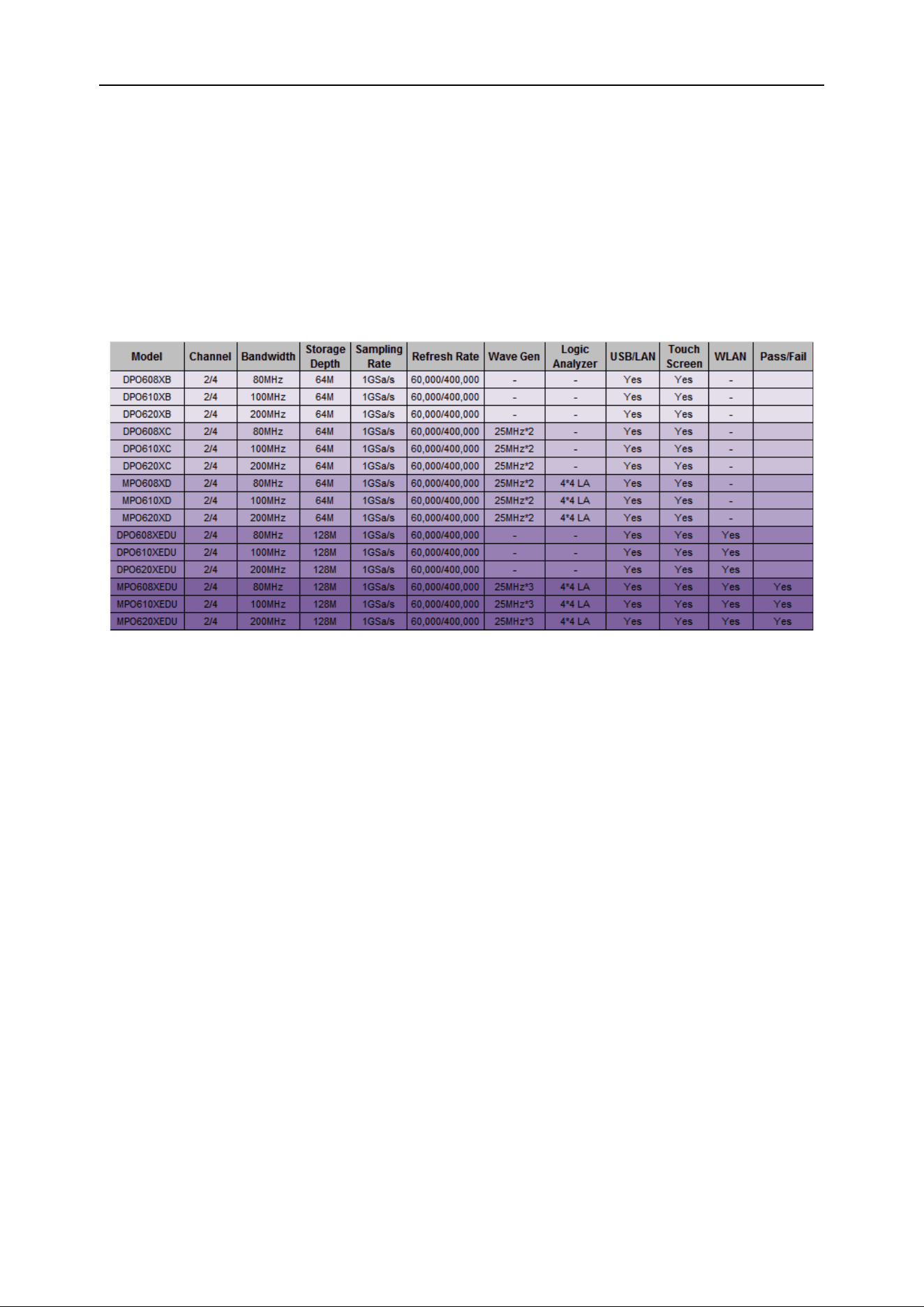
DPO6000, MPO6000 Series Digital Fluorescent Oscilloscope Product Manual V1.3
7
★Embedded help for easy access to information
★New and exquisite industrial design, convenient operation
Product model list
The MPO6000 / DPO6000 series includes the following models. Unless otherwise
specified, this manual uses the MPO6204EDU as an example to explain the functions
and operation methods of the oscilloscope.
Quick Start
This chapter describes the precautions when using the oscilloscope for the first time,
the front and rear panels of the oscilloscope, the user interface, and how to use the
built-in help system.
General inspection
Checking the shipping packaging
If you find that the packaging carton or foam protective pad is seriously damaged,
please keep it until the whole machine and accessories pass the electrical and me-
chanical tests.
Check the whole machine
If you find that the appearance of the instrument is damaged, that the instrument is not
working properly, or that it fails the performance test, please contact the dealer respon-
sible for this business.
Check random accessories
If you find that the accessory is missing or damaged, please contact the dealer respon-
sible for the business. Details of the attachments provided are described in "Appendix A:
DPO6000, MPO6000 Series Digital Fluorescent Oscilloscope Product Manual V1.3
8
Attachments" at the end of this note.
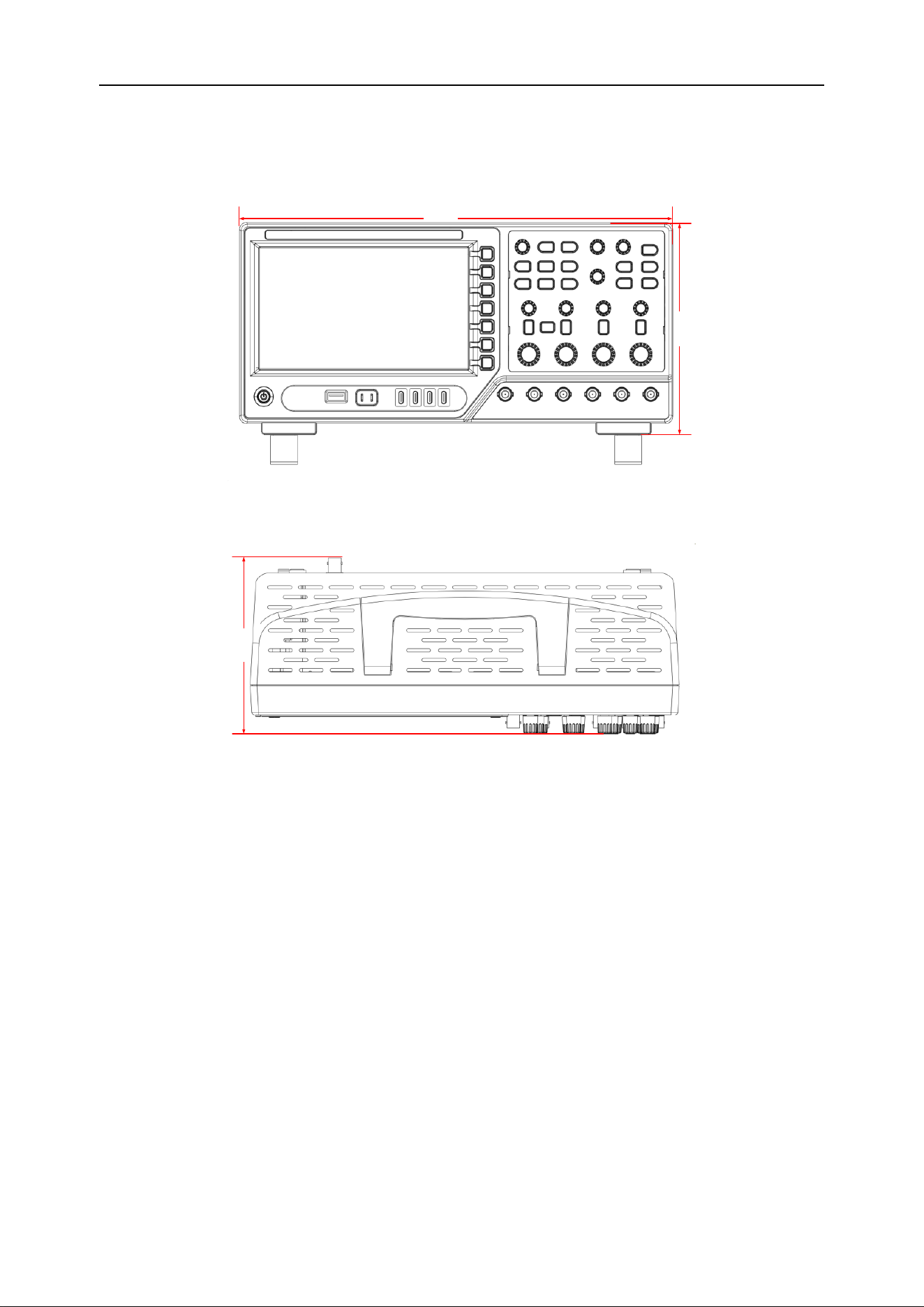
Physical dimension
318 mm
150 mm
Front view
140 mm
Top view
Ready to use the instrument
Adjusting the bracket
Properly adjust the stand so that it is upright, tilt the oscilloscope upward, and place the
oscilloscope stably, so as to better operate and observe the display screen.
DPO6000, MPO6000 Series Digital Fluorescent Oscilloscope Product Manual V1.3
9
Adjust the support feet
Connect the power cord as required
The specifications of the AC power source that this oscilloscope can input are: 100-
120Vac, 50/60/400Hz; 100-240Vac, 50/60Hz; 50W max.
Connect the oscilloscope to an AC power source using the power cord provided in the
accessory (shown below).
Power
jack
Connect the power supply
Startup check
When the oscilloscope is powered on, press the power switch in the lower left corner of
the front panel to start the oscilloscope. During startup, the oscilloscope performs a se-
ries of self-tests. During the self-test, the keyboard indicators light up according to a
certain sequence of rules. After the self-test ends, the startup screen appears.
DPO6000, MPO6000 Series Digital Fluorescent Oscilloscope Product Manual V1.3
10
Probe inspection
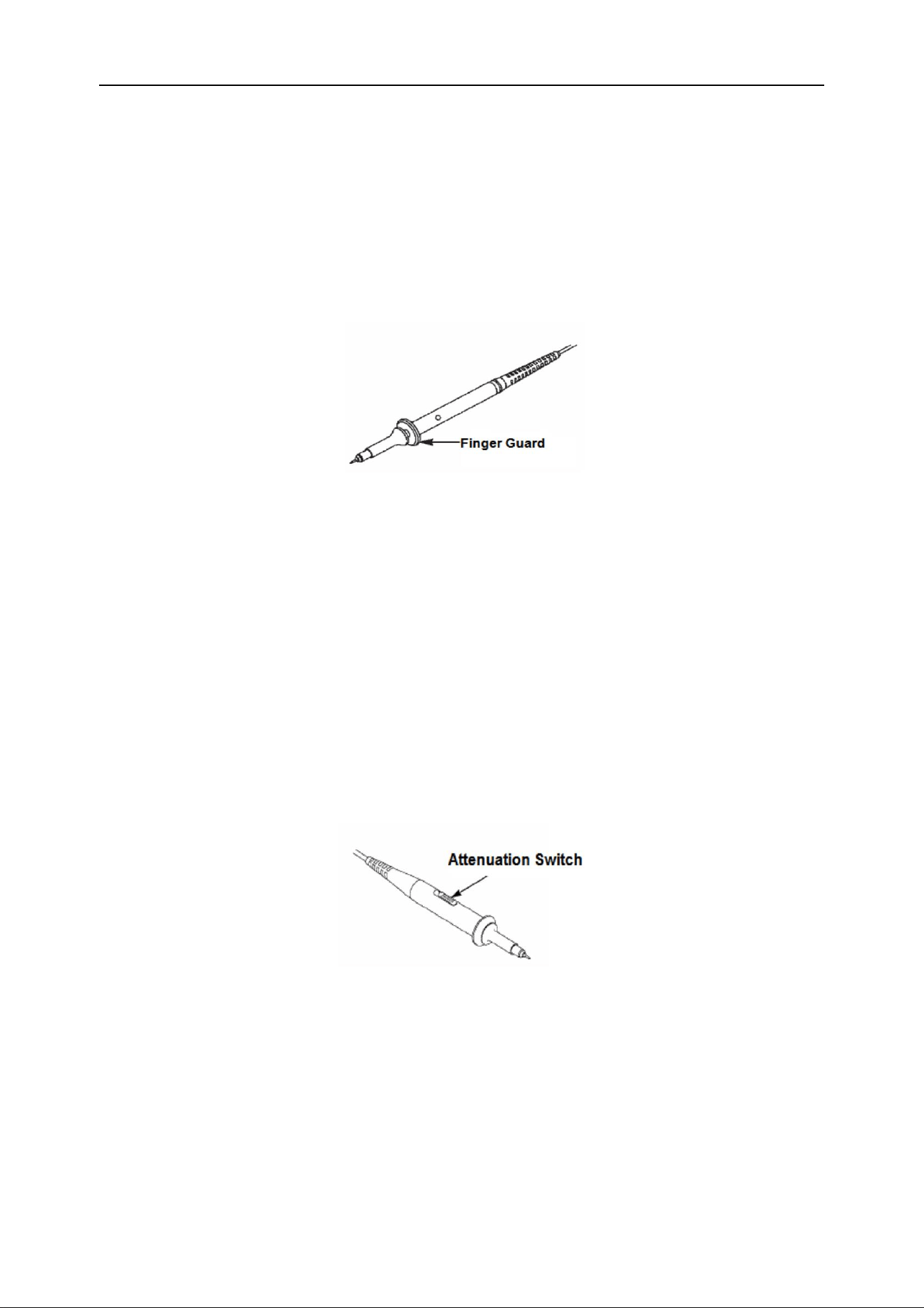
Safety
When using the probe, to avoid electric shock, keep your fingers behind the safety ring
on the probe body. Do not touch the metal part on the top of the probe when the probe
is connected to a high voltage power supply. Before making any measurements, con-
nect the probe to the oscilloscope and ground the ground terminal.
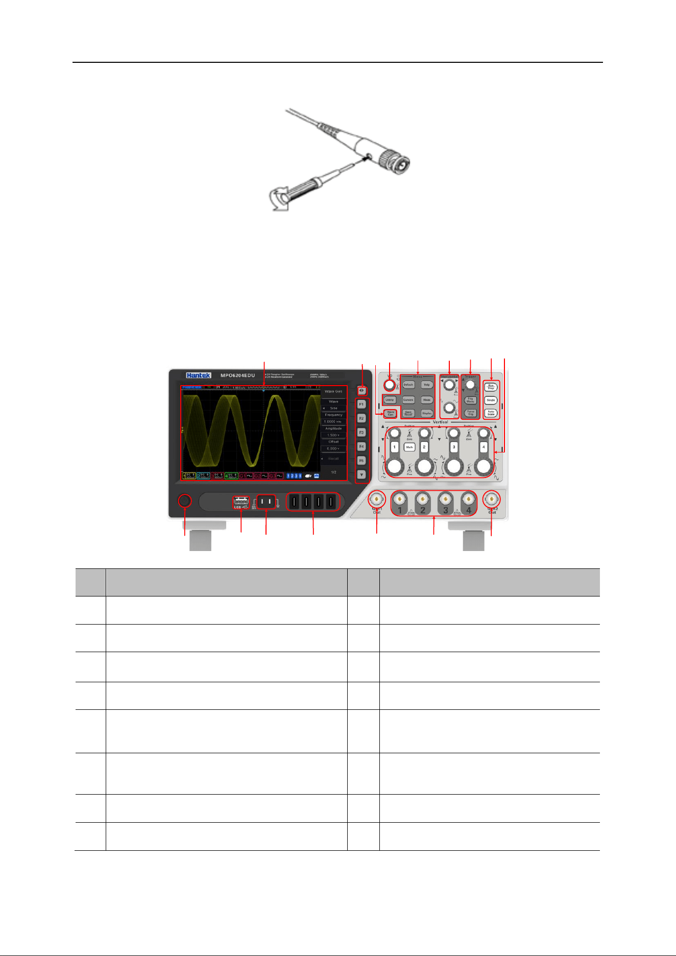
Probe attenuation setting
Probes have different attenuation coefficients, which affect the vertical scale of the sig-
nal. The "Probe Check" function verifies that the probe attenuation options match the
probe attenuation.
Press the "Vertical Menu" button (such as the [CH1] menu button) to select a probe op-
tion that matches the probe attenuation coefficient.
Make sure the "Attenuation" switch on the probe matches the "Probe" option in the os-
cilloscope, and set the switches to X1, X10.
When the Attenuation switch is set to X1, the probe limits the oscilloscope's bandwidth
to 6MHz. When the "Attenuation" switch is set to X10, the oscilloscope has full band-
width.
Connect the probe
DPO6000 series oscilloscopes are equipped with passive probes as standard, and
MPO6000 series are equipped with passive and digital probes as standard.
Connect the passive probe:
1. Connect the BNC end of the probe to the analog channel input on the front panel of
the oscilloscope.

DPO6000, MPO6000 Series Digital Fluorescent Oscilloscope Product Manual V1.3
11
2. Connect the probe ground alligator clip or ground spring to the circuit ground termi-
nal, and then connect the probe to the circuit under test.
Connect the logic probe:
1. Connect one end of the digital probe to the digital channel input interface on the front
panel of the oscilloscope (the digital probe has no direction).
2. Connect the other end of the digital probe to the signal under test. The MPO6000 se-
ries comes standard with four LP104 digital probes.
Check the probe voltage
Each time you connect a probe to an input channel, you should perform a probe check.
Use the "Vertical Menu" button; for example, press the CH1 menu button to set the
probe attenuation coefficient.
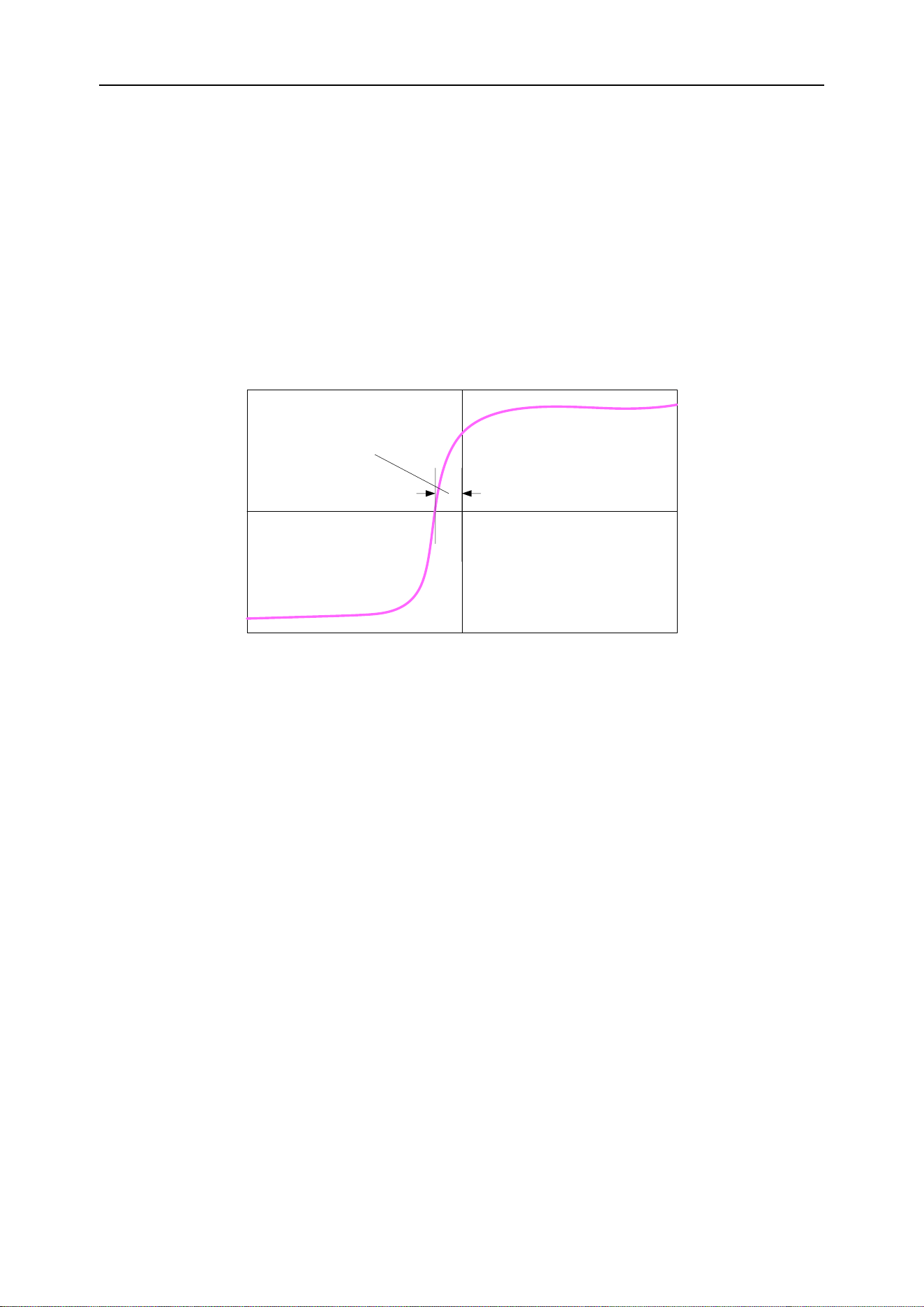
Manual probe compensation
When connecting the probe to any input channel for the first time, make this adjustment
to match the probe to the input channel. Uncompensated or compensated probes can
cause measurement errors or errors. To adjust the probe compensation, follow these
steps:
1. Set the probe option attenuation to 10X in the Channel Menu. Set the switch on the
probe to 10X and connect the probe to channel 1 of the oscilloscope. If using the probe
hook end, make sure that the hook end is firmly seated on the probe. Connect the
probe tip to the probe element: ~ 2V @ 1K Hz connector, and connect the reference
wire to the "probe element ground" connector, then press the "Auto Scale" button.
2. Check the shape of the displayed waveform
3. If necessary, use a non-metallic screwdriver to adjust the variable capacitance on the
probe until the waveform shown on the screen is "compensated correctly" as shown
above. Repeat this step if necessary. The adjustment method is shown in the figure be-
low.
Compensated correctly
Overcompensated
Undercompensated
DPO6000, MPO6000 Series Digital Fluorescent Oscilloscope Product Manual V1.3
12
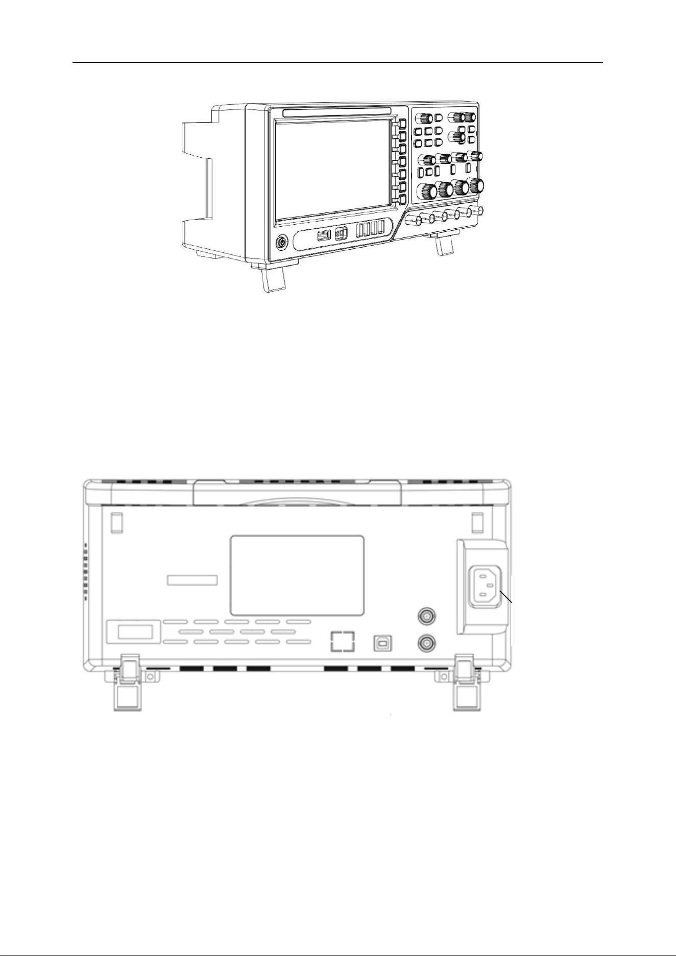
Front panel overview
The following content briefly describes and introduces the front panel part of the 6000
series oscilloscope, so that users can become familiar with the 6000 series digital oscil-
loscope in the shortest time.
1
2 3
4 5 6
7
8
9
10
11
13
12
16
1415
SN
Description
SN
Description
1
LCD
9
Vertical control system
2
Menu show/hide keys
10
Signal source 2 output channel
3
Signal source button (signal source series)
11
CH1~CH4 signal input channel
4
Multifunction knob
12
Signal source 1 output channel
5
Menu function buttons
13
LA1 ~ LA4 signal input channels
(MPO6000 series)
6
Level control system
14
Probe compensation signal out-
put/ground
7
Trigger control system
15
USB Host port
8
Shortcuts (Run/Stop, Single, Auto Scale)
16
Power On Key
DPO6000, MPO6000 Series Digital Fluorescent Oscilloscope Product Manual V1.3
13
Rear panel overview
1
2
34
5
67
1. Handle
Pull the handle vertically to carry the oscilloscope conveniently. When not needed, just
press down on the handle.
2. AC power jack
AC power input. Please use the power cord provided to connect the oscilloscope to AC
power, and press the power button on the front panel to turn it on.
3. AUX port trigger output and pass / fail [optional]
Trigger output:
When the oscilloscope generates a trigger, a pulse can be output through this interface.
This pulse is the signal of the oscilloscope's current capture rate. Connect this signal to
the waveform display device and measure the frequency of the signal. The measure-
ment result is the same as the current capture rate.
Pass / Fail:
In the pass / fail test, when the oscilloscope detects a failure, it will output a pulse
through this connector. When no failure is detected, it will continuously output a low
level through this connector.
4. Signal source 3 source output [MPO6000EDU Series]
Signal source 3 output is only for the 3-channel signal source built into the oscilloscope.
When the oscilloscope signal source 3 is turned on, the signal source port outputs sig-
nals according to the current settings.
5. USB Device
This interface allows you to connect the oscilloscope to a computer or a printer. When
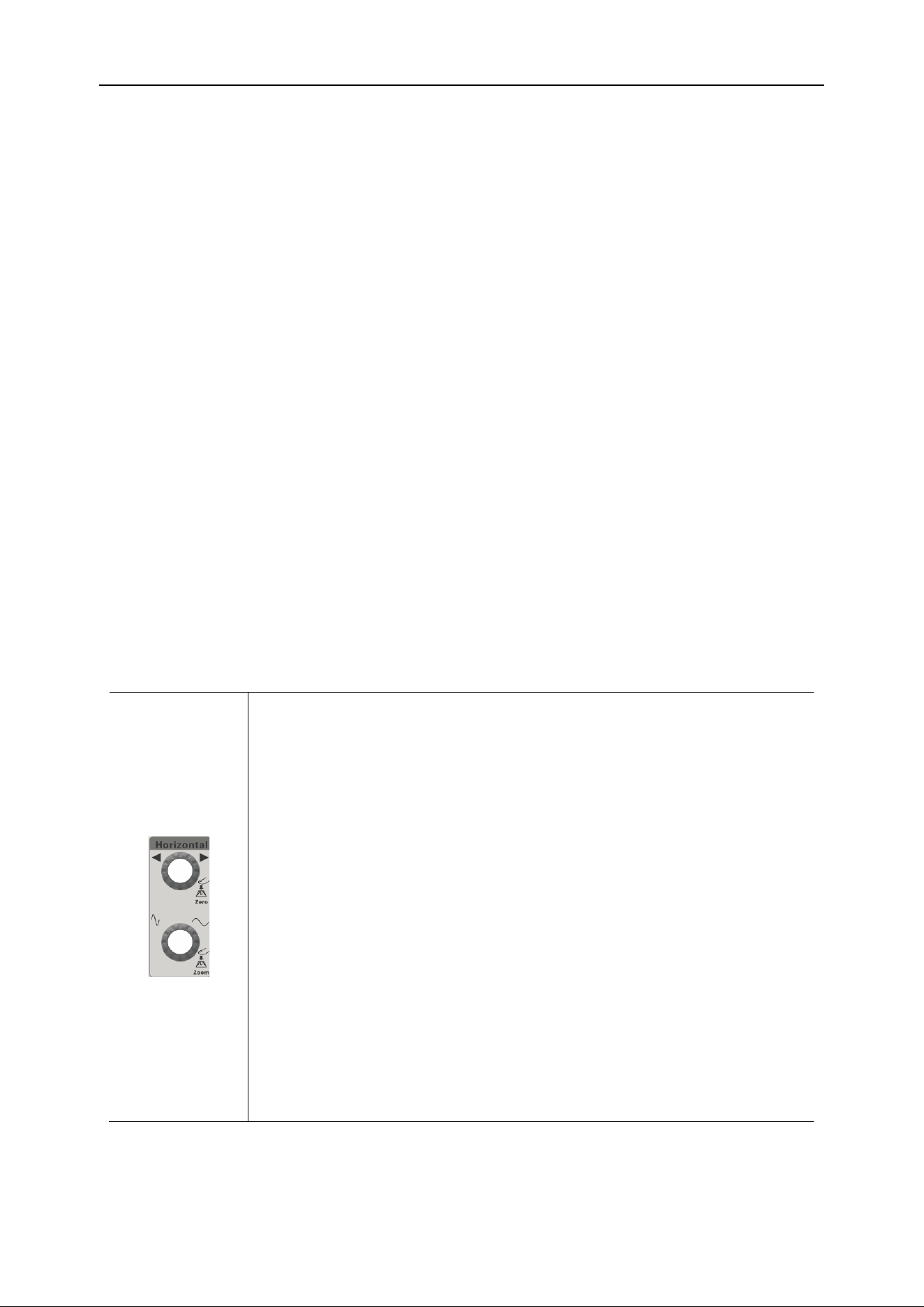
DPO6000, MPO6000 Series Digital Fluorescent Oscilloscope Product Manual V1.3
14
connected to a computer, users can send SCPI commands or custom programming to
control the oscilloscope through the host computer software. When the printer is con-
nected, the user prints the waveform displayed on the screen through the printer.
6. LAN / UART
LAN
Connect the oscilloscope to the network through this interface to remotely control it.
This oscilloscope complies with the LXI CORE 2011 DEVICE class instrument standard
and can quickly build a test system.
UART [optional]
This interface connects the oscilloscope to a control system for remote control.
7. HDMI interface [optional]
You can connect the oscilloscope to a monitor with an HDMI display through this inter-
face to get a larger display.
Front panel functions
Introduction of the main keys
Level control system
Horizontal offset:
Modify the horizontal displacement. When the knob is turned, the
trigger point moves left and right relative to the center of the
screen. During the modification, the waveforms of all channels
move left and right, and the horizontal displacement information in
the upper right corner of the screen changes in real time.
Press this knob to quickly reset the horizontal displacement.
Horizontal time base:
Modify the horizontal time base. Turn clockwise to decrease the
time base and turn counterclockwise to increase the time base.
During the modification, the waveforms of all channels are ex-
panded or compressed, and the time base information at the top
of the screen changes in real time.
Press this knob to quickly switch between single and double win-
dow display modes.
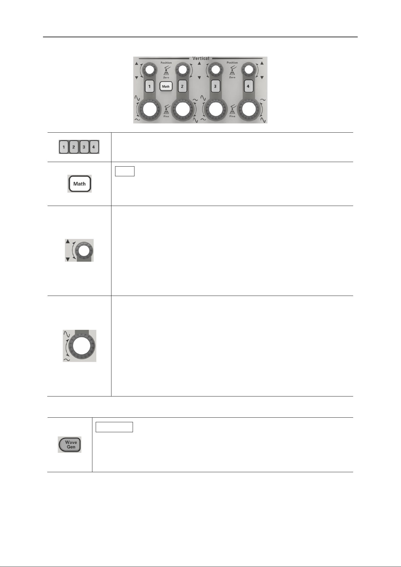
Vertical control system
DPO6000, MPO6000 Series Digital Fluorescent Oscilloscope Product Manual V1.3
15
Signal source
WaveGen:
Press this key to enter the setting interface of the signal source. Set
the waveform and parameters of the output signal from the signal
source.
Note: This function is only applicable to digital oscilloscopes with signal source chan-
nels.
Trigger control
Analog input channel switch. Press any button to open the corre-
sponding channel menu, and press again to close the channel.
Math:
Press the "Math" button to open the Math setup menu, and press
again to close the Math function.
Vertical offset:
Modify the vertical shift of the current channel waveform. Turn
clockwise to increase displacement, turn counterclockwise to de-
crease displacement. During the modification, the waveform will
move up and down, and the displacement information displayed
at the top right of the screen will change in real time.
Press this knob to quickly zero the vertical displacement.
Vertical voltage:
Modify the vertical scale of the current channel. Turn clockwise to
decrease gears and turn counterclockwise to increase gears.
During the modification, the waveform display amplitude will in-
crease or decrease, and the gear information at the bottom left of
the screen will change in real time.
Press this knob to quickly switch the vertical scale adjustment
mode to "Coarse" or "Fine".
DPO6000, MPO6000 Series Digital Fluorescent Oscilloscope Product Manual V1.3
16
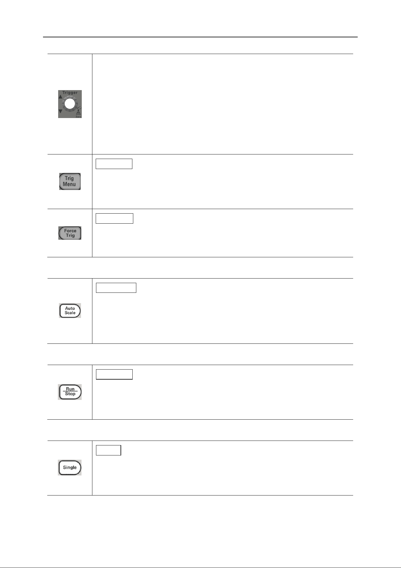
Trigger level:
Modify the trigger level. Turn clockwise to increase the level, and turn
counterclockwise to decrease the level. During the modification, the
trigger level line moves up and down, and at the same time, the value
in the trigger level message box at the top right of the screen changes
in real time.
Press this knob to quickly restore the trigger level to the zero point of
the trigger data source.
TrigMenu:
Press this key to open the trigger operation menu. This oscilloscope
provides a variety of trigger types, please refer to the detailed introduc-
tion in "Trigger System".
ForceTrig:
A short press of this key will force a trigger signal.
Press and hold this key to open the history waveform.
Automatic waveform display
AutoScale:
Press this key to enable the automatic waveform setting function. The
oscilloscope will automatically adjust the vertical scale, horizontal time
base, and trigger mode according to the input signal to achieve the
best waveform display.
Operational control
Run/Stop:
Press this key to "run" or "stop" waveform sampling. In the Run state,
the green backlight of the key is on; in the Stop state, the red backlight
of the key is on.
Single trigger
Single:
Press this key to set the trigger mode of the oscilloscope to “Single”. In
single trigger mode, press the “Force Trig” key to immediately gener-
ate a trigger signal.
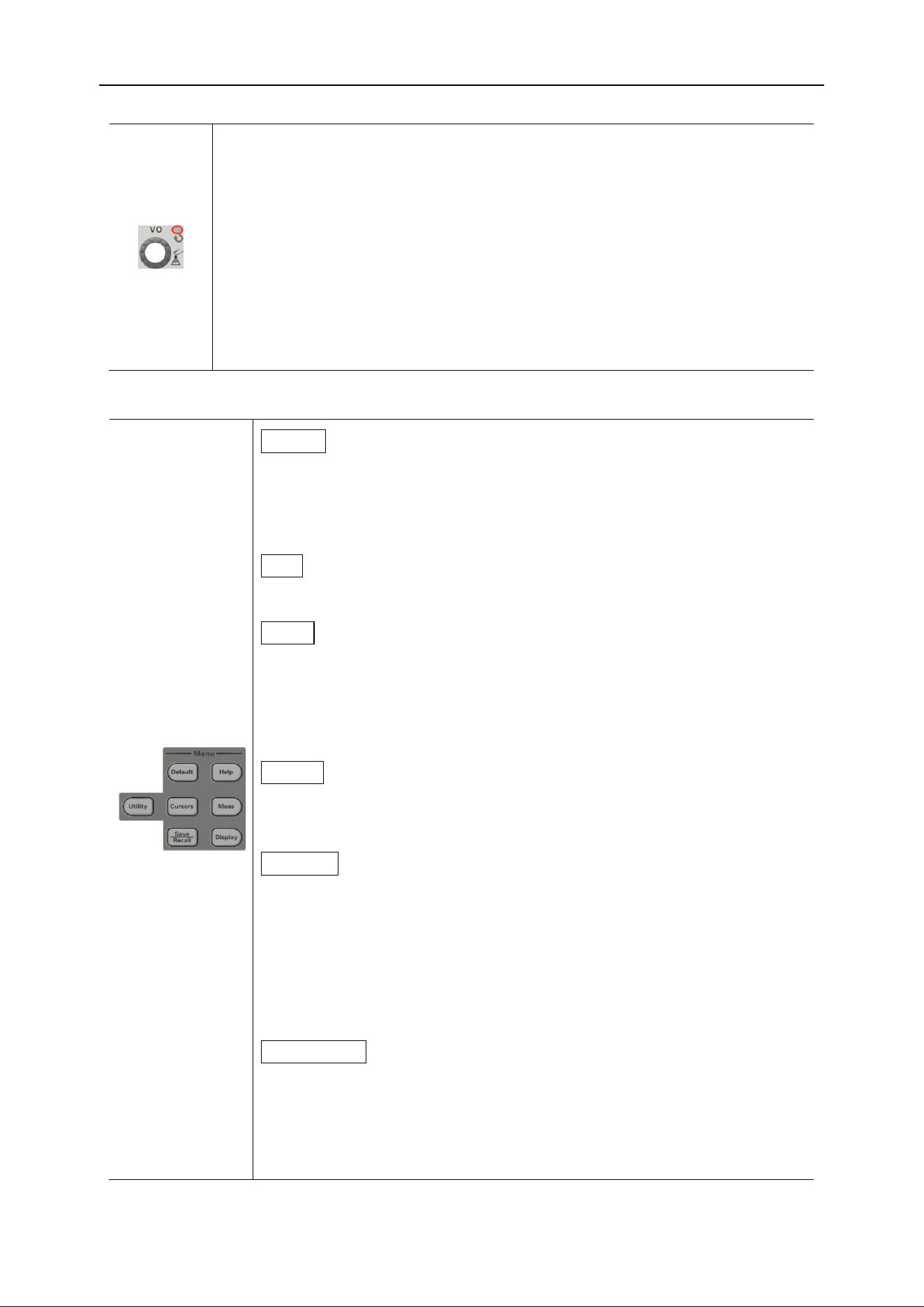
Multifunction knob
DPO6000, MPO6000 Series Digital Fluorescent Oscilloscope Product Manual V1.3
17
V0:
The multi-function knob can perform various settings, such as adjust-
ing the waveform brightness, trigger time, selecting the trigger type,
selecting the trigger source, the signal source waveform, frequency,
offset, amplitude, etc .; the multi-function indicator does not light up
when the menu is not operated. The operation is that the multi-function
indicator is on. Turn the knob to adjust the settings listed above. Turn
clockwise to increase and counterclockwise to decrease. Press the
knob to select this option.
Function menu
Default:
Press the key briefly to execute the corresponding default setting.
Long press this key to enter the Default function preset, you can
choose factory settings, default settings, user settings.
Help:
Press this key to open and close the built-in help system.
Utility:
Press this key to enter the system function setting menu. Set sys-
tem related functions or parameters, such as interface, sound,
language, etc. In addition, some advanced features are support-
ed, such as pass / fail tests.
Cursor:
Press this key to enter the cursor measurement menu. The oscil-
loscope provides two cursor modes: manual and tracking.
Measure:
Press this key to enter the measurement setting menu. You can
set the measurement data source, turn the digital multimeter on
or off, all measurements, and statistics functions. Press “All
Measurements” to open the measurement of 42 waveform pa-
rameters, and the measurement results will appear at the bottom
of the screen.
Save/Recall:
Press this key shortly to enter the file storage and recall interface.
The types of files that can be stored include: setup, waveform,
reference, CSV. Supports internal and external storage and disk
management.
DPO6000, MPO6000 Series Digital Fluorescent Oscilloscope Product Manual V1.3
18
Long press this key to save the picture in .bmp format to external
storage.
Display:
Press the key shortly to enter the display setting menu. Set the
waveform display type, afterglow time, waveform brightness,
screen grid and grid brightness.
Press and hold this key to clear the afterglow, and then collect or
count again.
User interface
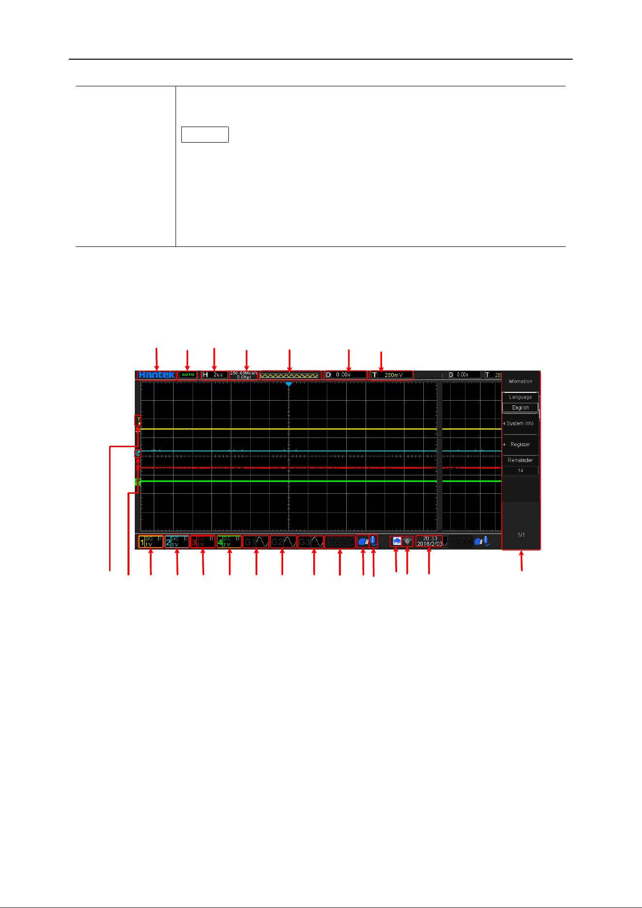
This section will let users know the front operation panel of this series of digital oscillo-
scopes before using.
1
2
3
4
5
6
7
8
10
121314
15
16
1718
19
20
21 9
11
22
23
1. Hantek trademark
Open the "Touch Screen" in "Utility", and touch the Hantek logo in the upper left corner
of the screen-> scan the QR code to quickly enter the wizard interface.
2. Running status:
AUTO: The oscilloscope works in automatic mode and acquires waveforms without
triggers.
READY: All pre-trigger data has been acquired and the oscilloscope is ready to accept
the trigger.
TD: The oscilloscope has been triggered.
ROLL: In scroll mode, the oscilloscope continuously acquires and displays waveform
DPO6000, MPO6000 Series Digital Fluorescent Oscilloscope Product Manual V1.3
19
data.
STOP: The oscilloscope stops acquiring waveform data.
ARM: pre-trigger state.
3. The main time base of the current window
Represents the length of time represented by each division on the horizontal axis of the
screen.
4. Current sampling rate, sampling points
Displays the current sampling rate and memory depth of the analog channels.
The sampling rate and memory depth change as the horizontal time base changes.
5. Waveform memory
Waveform in memory
Waveform on screen
6. Horizontal trigger time
Use the horizontal offset knob to adjust this parameter. Press the knob to quickly reset
the horizontal displacement.
7. Trigger Level
Use the trigger level knob to adjust this parameter. Press the knob to quickly reset the
trigger level.
8. Operation menu displays different information of each function key
9. Time display of oscilloscope
10. WIFI status display
11. LAN connection status indication
If the icon is lit, the LAN is connected.
12. USB external storage device status display
If the icon is lit, the USB external storage device is connected.
13. USB host computer connection status display
If the icon is on, the USB host computer is connected.

DPO6000, MPO6000 Series Digital Fluorescent Oscilloscope Product Manual V1.3
20
14. Logic analyzer status display
If the icon is lit, the LA channel is connected.
15. Gen3 status display [MPO6000EDU series]
If the icon is lit, the Gen3 channel is turned on.
16. Gen2 status display [signal source series]
If the icon is lit, the Gen2 channel is turned on.
17. Gen1 status display [signal source series]
If the icon is lit, the Gen1 channel is turned on.
18. CH4 status display [4-channel series]
If the icon is lit, the CH4 channel is turned on.
19. CH3 status display [4-channel series]
If the icon is lit, the CH3 channel is turned on.
20. CH2 status display
If the icon is lit, the CH2 channel is turned on.
21. CH1 status display
If the icon is lit, the CH1 channel is turned on.
22. Channel zero-scale position display
23. Channel trigger level position display
Sampling system
To understand the oscilloscope's waveform acquisition system, you need to understand
the sampling principle and understand the relationship between sampling rate and
memory depth.
Sampling principle
According to the Nyquist sampling principle, in order to restore the analog signal with-
out distortion, the sampling frequency should be greater than twice the highest fre-
quency in the analog signal spectrum (Fs> 2Fmax). The higher the sampling rate, the
later the recovered waveform will be closer to the original signal, but the system re-
quirements will be higher, and the conversion circuit must have a faster conversion
speed.
DPO6000, MPO6000 Series Digital Fluorescent Oscilloscope Product Manual V1.3
21
Waveform aliasing
If the sampling cannot be satisfied (Fs> 2Fmax), the waveform frequency when recon-
structing the sampled data is smaller than the frequency of the actual signal. The most
common aliasing is dithering on the fast edge.
The following two measures can avoid aliasing:
1. Increase the sampling frequency to more than twice the highest signal frequency;
2. Introduce or increase the parameters of the low-pass filter; the low-pass filter is often
called an anti-aliasing filter. Anti-aliasing filters can limit the bandwidth of the signal to
meet the conditions of the sampling theorem. In theory, this is feasible, but it is impos-
sible in practice. Because filters cannot completely filter out signals above the Nyquist
frequency, there is always some "small" energy outside the bandwidth required by the
sampling theorem. However, anti-aliasing filters can make these energies small enough
to be negligible.
Waveform distortion
Due to the low sampling rate, some waveform details are missing, which makes the
waveform displayed by the oscilloscope to be different from the actual waveform.
Waveform miss
Because the sampling rate is too low, the waveform when reconstructing the sampled
data does not reflect all the actual signals.

DPO6000, MPO6000 Series Digital Fluorescent Oscilloscope Product Manual V1.3
22
Sampling rate and memory depth
Sampling rate
The highest sampling rate of DPO6000 / MPO6000 is 1GSa/s. In the actual use of the
oscilloscope, the sampling rate is determined by the current horizontal time base scale
and storage depth. The sampling rate can be changed by adjusting the horizontal time
base through the horizontal gear knob, or by switching the memory depth, the sampling
rate value changes in real time and is displayed in the status bar at the top left of the
screen.
Memory depth
Storage depth refers to the number of waveform points that the oscilloscope can store
in one triggered acquisition, and it reflects the storage capacity of the acquisition
memory. DPO6000 / MPO6000 series oscilloscopes have a maximum storage depth of
128Mpts.
The relationship between the oscilloscope's storage depth, sampling rate, and sampling
time is as follows:
Sampling time = memory depth / (sampling rate (Sa/s))
For example: if the sampling rate is 1GSa/s and the storage depth is 32K, the actual
sampling time is:
Sampling time = 3,2000 / 1,000,0000,000 s = 32×10
-6
s = 32us
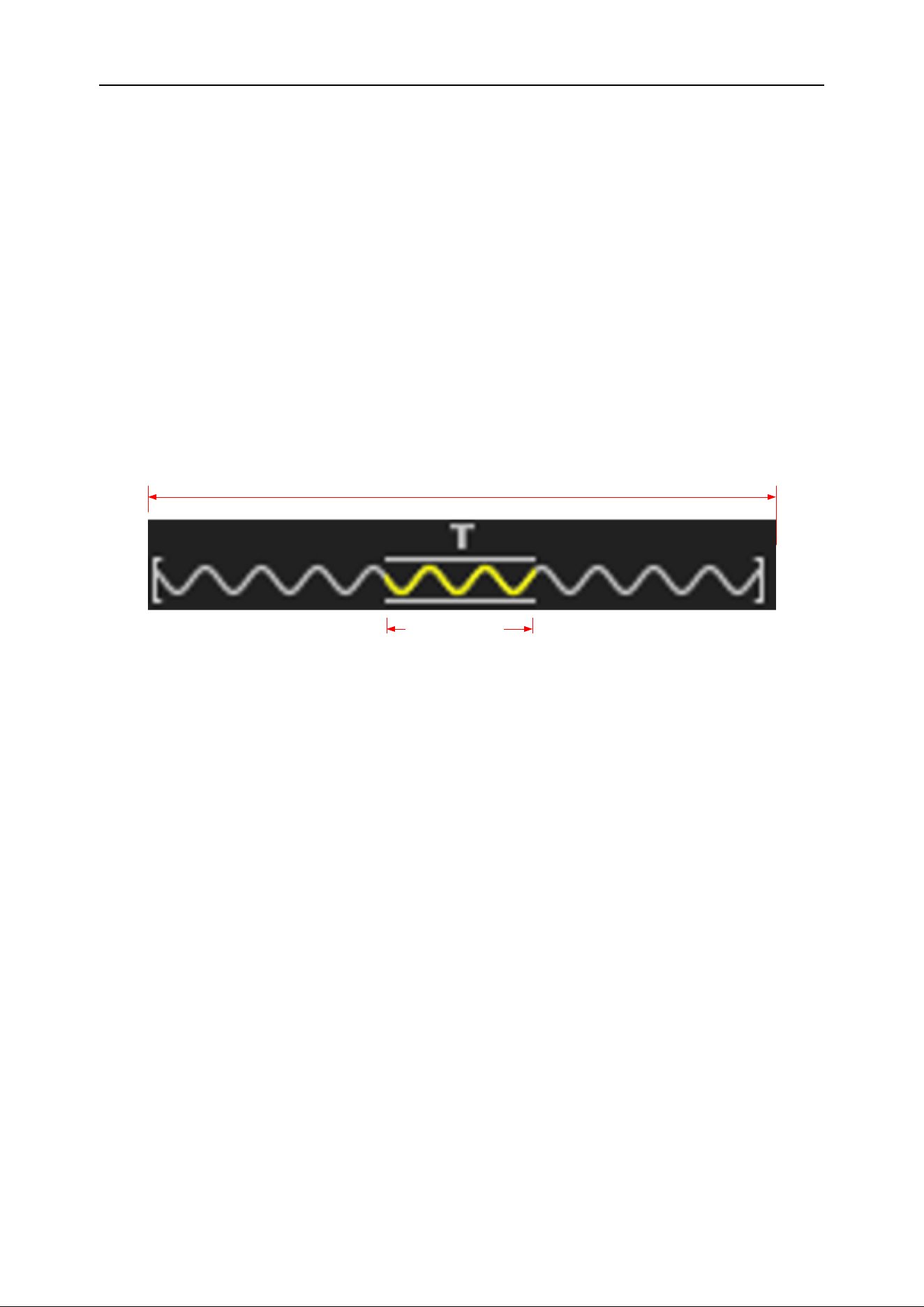
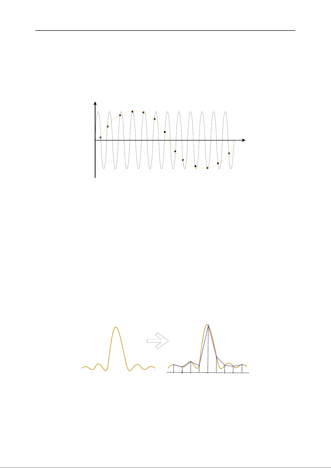
Waveform interpolation
Under real-time sampling, the oscilloscope acquires discrete samples of the displayed
waveform. In general, waveforms displayed by dots are difficult to observe. In order to
increase the signal visibility, digital oscilloscopes generally use the interpolation display
mode. The interpolation method is a processing method of "connecting various acquisi-
tion points" and using some points to estimate the entire shape of the waveform. For
real-time sampling using interpolation, even if the oscilloscope only collects fewer sam-
pling points in a single pass, interpolation can be used to fill in the gaps between points
DPO6000, MPO6000 Series Digital Fluorescent Oscilloscope Product Manual V1.3
23
and reconstruct accurate waveforms. The interpolation method is divided into sine in-
terpolation, linear interpolation and step interpolation.
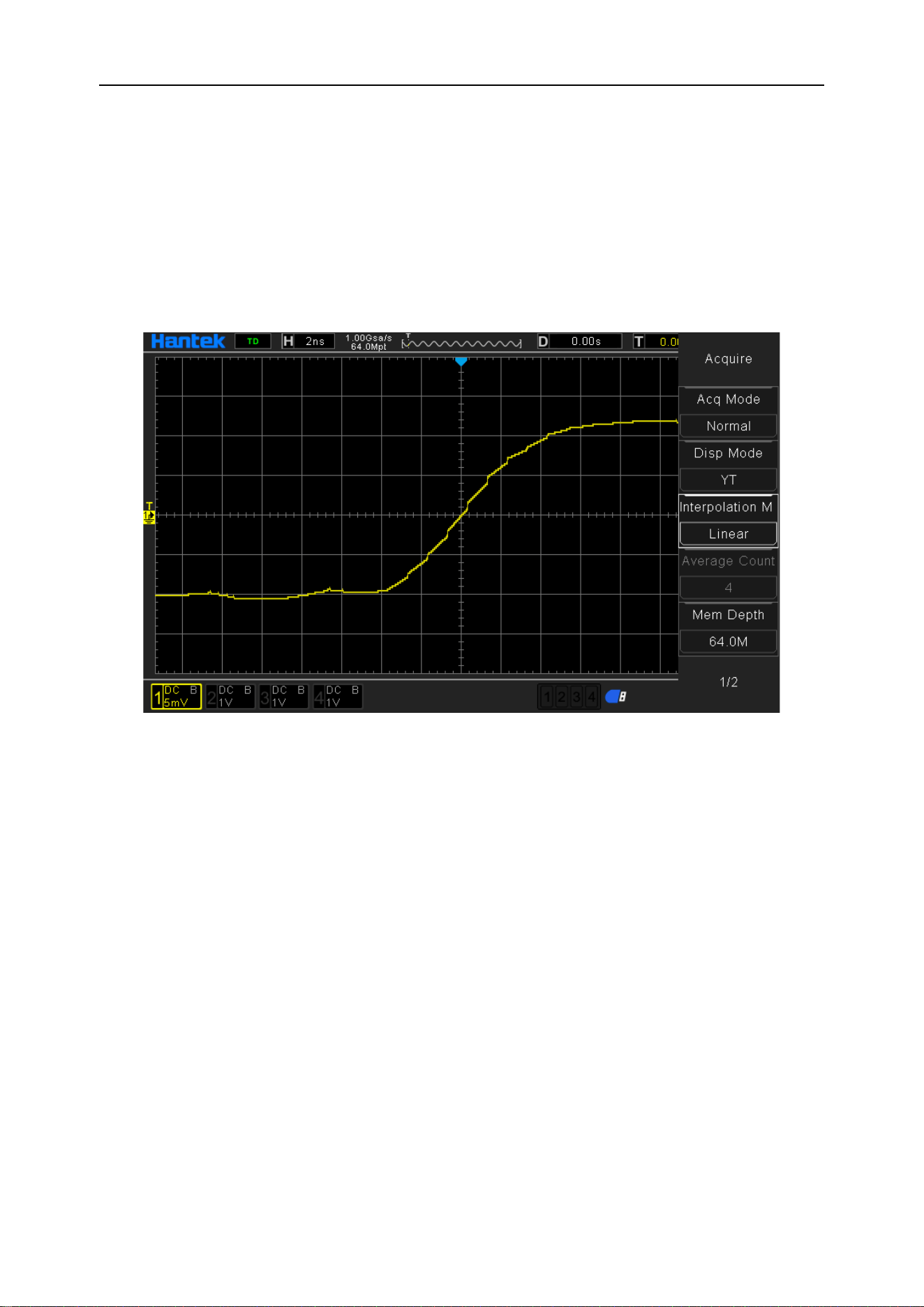
Linear interpolation
Connect straight lines directly at adjacent points. This method is limited to reconstruct-
ing straight-edge signals, such as square waves. The sine interpolation method uses
curves to connect the sampling points, which is more versatile.
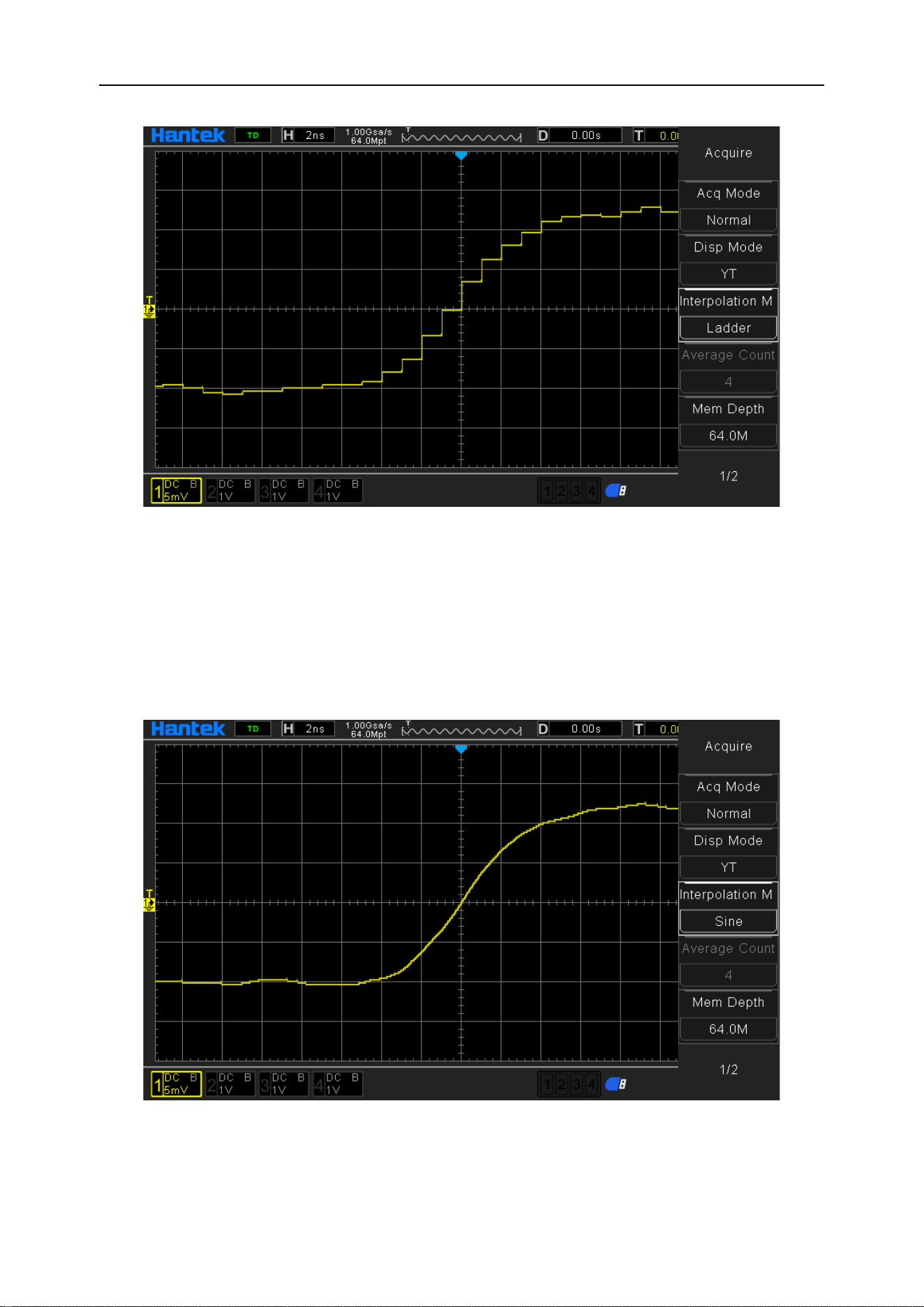
Step interpolation
Insert the value of the previous sampling point between adjacent samples. This interpo-
lation algorithm is the same as the normal actual sampling of the oscilloscope ADC.
The sample-and-hold method is used to interpolate data to improve the signal sampling
rate.
DPO6000, MPO6000 Series Digital Fluorescent Oscilloscope Product Manual V1.3
24
Sine interpolation
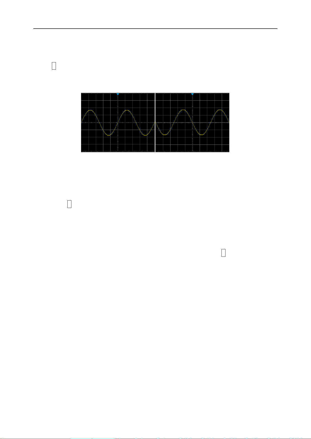
Use mathematical processing to calculate the results in the actual sample interval. This
method bends the signal waveform to produce a more realistic common shape than
pure square waves and pulses. When the sampling rate is 3 to 5 times the system
bandwidth, sine interpolation is recommended. The following figure shows the com-
pletely different display effect after using this interpolation method.
Through the comparison of the acquired signal waveforms of the three interpolation
methods above, it can be clearly seen that the three interpolation methods, the sine in-
terpolation method, are relatively smooth to fit the signal waveform, and also reflect the
DPO6000, MPO6000 Series Digital Fluorescent Oscilloscope Product Manual V1.3
25
signal waveform more realistically. For signal interpolation, we use sine interpolation by
default.
Operational control
You can use the two buttons Run/Stop and Single on the front panel of the oscilloscope
to start or stop the oscilloscope's sampling system.
When the Run/Stop key is green, the oscilloscope is running, that is, and the oscillo-
scope is acquiring data. To stop collecting data, press the Run/Stop key to display red,
indicating that data collection has stopped. To capture and display a single acquisition,
whether the oscilloscope is running or stopped, press Single. When the input single-
shot signal meets the trigger conditions, the oscilloscope captures and stores and dis-
plays the waveform. At this time, even if there is another signal input to the oscilloscope,
it will not be processed. If you want to capture again, you need to perform a single set-
up again.
When the Single key is pressed, the trigger mode is temporarily set to "Normal" (to
prevent the oscilloscope from triggering immediately and automatically), the button light
is orange and the oscilloscope waits for the trigger condition to appear before display-
ing the waveform. When the oscilloscope triggers, the single acquisition result is dis-
played and the operation is stopped, and the Run/Stop key is displayed in red. Press
the Single key again to acquire another waveform.
Collection method
Press the front panel Utility-> Acquisition-> Acquisition Mode, select the desired acqui-
sition mode (the default is "normal"), press the knob to select this mode, and the user
can also press the [Acquisition Mode] key continuously to switch.
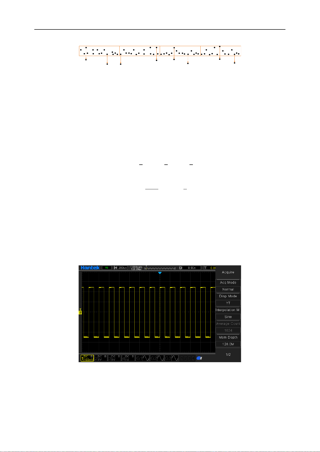
Normal
In this mode, the oscilloscope samples the signal at equal time intervals to reconstruct
the waveform. For most waveforms, using this mode produces the best display results.
Peak
In this mode, the oscilloscope collects the maximum and minimum values of the signal
during the sampling interval to obtain the signal envelope or narrow pulses that may be
lost. Using this mode can avoid aliasing of the signal, but the display noise is relatively
large.
In this mode, the oscilloscope can display all pulses that are at least as wide as the
sampling period.
DPO6000, MPO6000 Series Digital Fluorescent Oscilloscope Product Manual V1.3
26
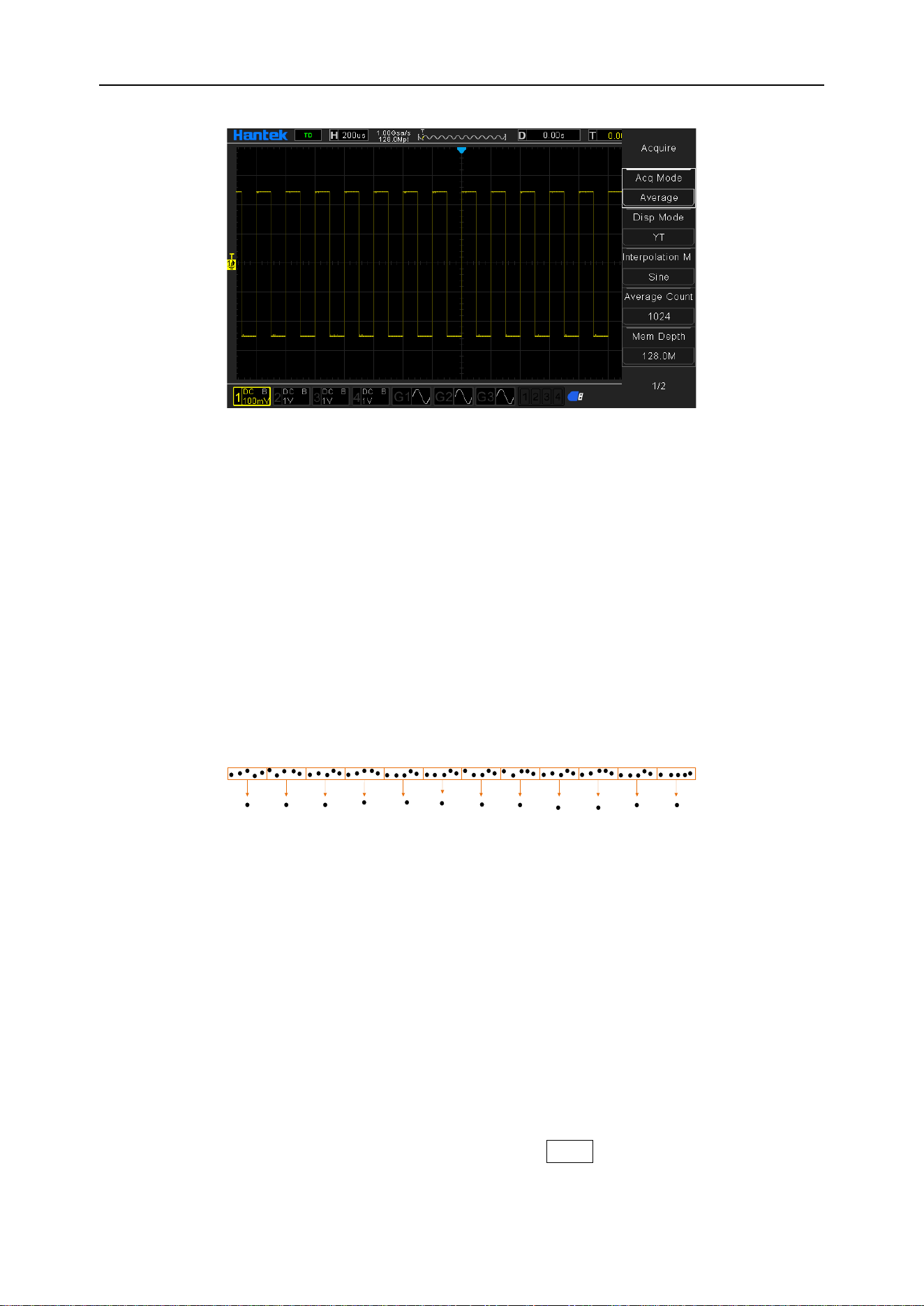
Average
In this mode, the oscilloscope averages the waveforms of multiple samples to reduce
random noise on the input signal and improve vertical resolution. The higher the num-
ber of averages, the lower the noise and the higher the vertical resolution, but the
slower the response of the displayed waveform to waveform changes.
DPO6000 / MPO600 series oscilloscopes use a stable average of the first n acquisi-
tions, and then take the exponential average method. These two algorithms can always
show the trend of changing waveforms. The stable average algorithm is as follows:
Among them,
is the averaged sampling value, X
i
is the i-th sampling value, and n
is the current average number of times.
After selecting the "Average" mode, press the "Average Times" menu to set the desired
average times, which can be set to 2, 4, 8, 16, 32, 64, 128, 256, 512, or 1024. The de-
fault is 2.
Example waveform without averaging:
Example of waveform after 1024 averages:
DPO6000, MPO6000 Series Digital Fluorescent Oscilloscope Product Manual V1.3
27
High resolution
This mode uses an oversampling technique to average the neighboring points of the
sampled waveform to reduce random noise on the input signal and produce a smoother
waveform on the screen. It is usually used when the sampling rate of the digitizer is
higher than the storage rate of the acquisition memory.
The high-resolution mode is actually a low-pass filtering method, so the bandwidth of
the measured signal is limited, that is, the measurement accuracy is improved by sacri-
ficing the bandwidth of the measured signal. With the calculation of the number of adja-
cent points used, increasing the effective number of digits will increase accordingly. The
DPO6000 / MPO6000 series oscilloscopes can be enhanced to a maximum of 12 digits.
In high-resolution mode, the oscilloscope is always running in the highest sampling rate
mode, and the number of enhancement bits changes with the oscilloscope's time base.
Note: The averaging method used by "Average" and "High Resolution" modes is differ-
ent. The former is "Multiple Sampling Average" and the latter is "Single Sampling Aver-
age".
Sampling rate
The sampling rate is the number of times (Sa/s) that the oscilloscope samples the sig-
nal in unit time. DPO6000 / MPO6000 series oscilloscope single channel maximum re-
al-time sampling rate of 1GSa/s, and will automatically switch according to the current
acquisition mode, memory depth, time base settings, automatically calculate the ap-
propriate sampling rate, without the need for users to manually set.
Function selection operation
By switching the memory depth {press the front panel Utility-> Acquisition-> Memory
Depth}.

DPO6000, MPO6000 Series Digital Fluorescent Oscilloscope Product Manual V1.3
28
By selecting the horizontal time base knob {turn the front panel horizontal time base
knob}.
By changing the acquisition method {press Utility-> Acquisition-> Acquisition Mode on
the front panel}
Note: The current waveform sampling rate is displayed in the status bar at the top of
the screen.
Horizontal control system
Time base mode
On the front panel, press the front-panel Utility-> Acquisition-> Display Mode menu.
The F2 display mode control menu allows the user to select the desired time-base
mode.
DPO6000 / MPO6000 series oscilloscopes include three time base display modes: YT
mode, XY mode, and rolling mode [YT mode is the default].
YT mode
In this mode, the Y-axis represents the amount of normal voltage and the X-axis repre-
sents the amount of time.
Note: In this mode, when the horizontal time base is set to 100ms or more, the instru-
ment enters the scan mode.
In YT mode, when the horizontal time base is set to 100ms/div or slower, the oscillo-
scope enters the scan mode. In this mode, the oscilloscope first collects the data to the
left of the trigger point, and then waits for the trigger condition. Then continue to com-
plete the waveform to the right of the trigger point and display the currently acquired
waveform data.
Note: It is recommended to set the “channel coupling” mode to “DC” in the scan mode
to observe the low signal frequency.
YT single window display mode
DPO6000, MPO6000 Series Digital Fluorescent Oscilloscope Product Manual V1.3
29
YT dual window display mode
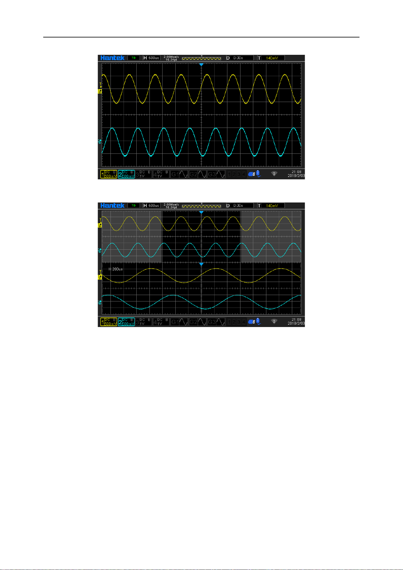
XY mode
In this mode, the oscilloscope converts the two input channels from voltage-time dis-
play to voltage-voltage display. The X-axis Y-axis combination can be CH1-CH2 or
CH3-CH4. The Lissajous method can conveniently measure the phase difference be-
tween two signals at the same frequency. The figure below shows the measurement
principle of phase difference.
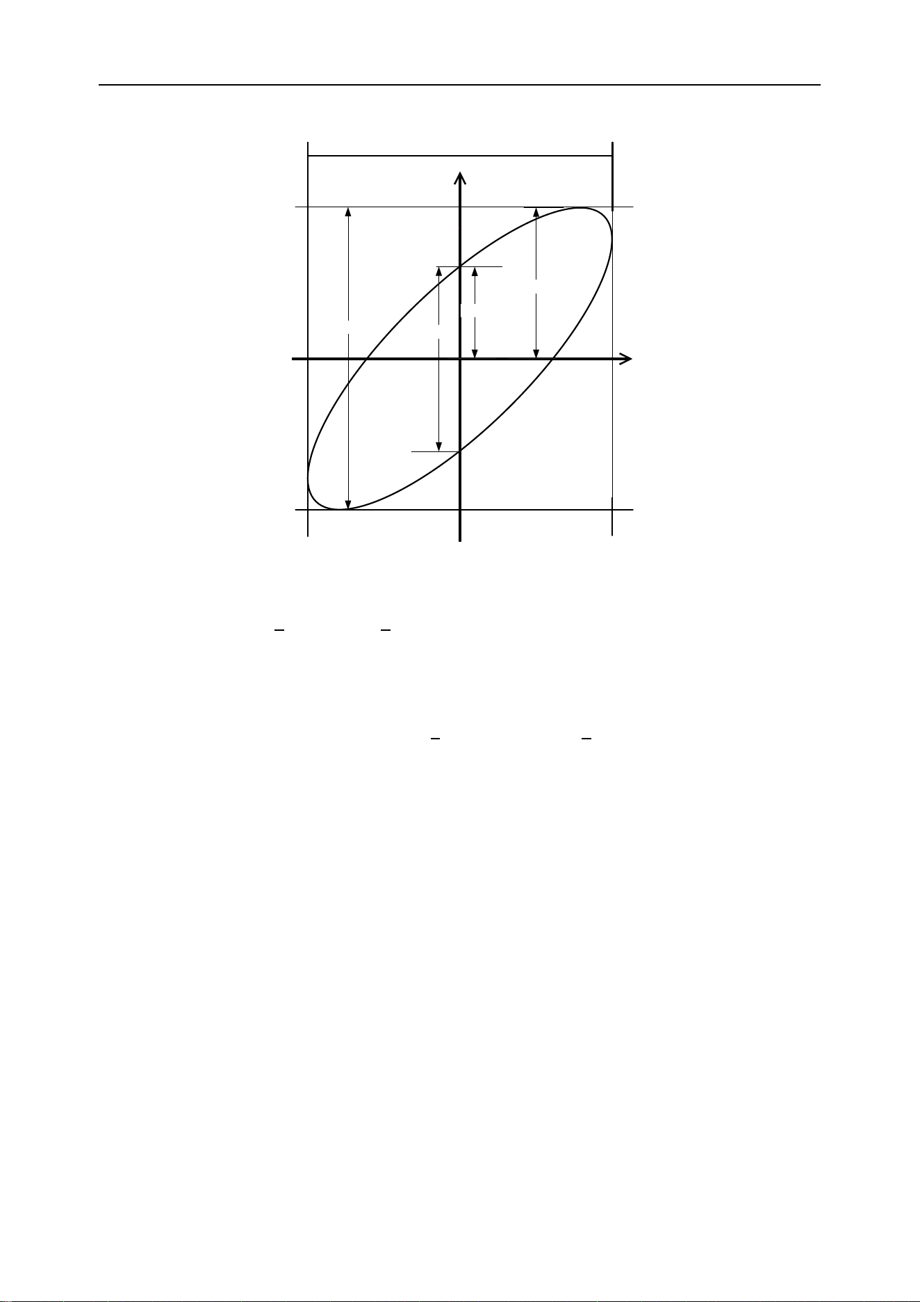
DPO6000, MPO6000 Series Digital Fluorescent Oscilloscope Product Manual V1.3
30
A
The signal must be centered horizontally
B
C
D
Ⅰ
Ⅱ
Ⅲ
Ⅳ
Phase difference measurement schematic
According to
or
, θ is the phase difference angle between the chan-
nels, and the definitions of A, B, C, and D are shown in the figure above. Therefore, the
phase difference angle can be obtained, that is:
Or
If the major axis of the ellipse is in the quadrants I and III, then the obtained phase dif-
ference angle should be in the quadrant III, that is, within (0 to π / 2) or (3π / 2 to 2π). If
the major axis of the ellipse is in the quadrants II and IV, then the obtained phase dif-
ference angle should be in the quadrants II and III, that is, within (π / 2 to π) or (π to 3π
/ 2). The X-Y function can be used to test the phase change of a signal through a circuit
network. Connect the oscilloscope to the circuit and monitor the input and output sig-
nals of the circuit.
Note:
When XY mode is turned on, Scan Mode is automatically turned off.
In XY mode, the oscilloscope automatically selects the channel combination "CH1-
CH2" or "CH3-CH4".
In XY mode: "Scan mode", "Vector display", "Protocol decoding", "Acquisition mode",
"Pass / Fail test", "Digital channel", "Persistence time" have no effect.
XY single window display mode
DPO6000, MPO6000 Series Digital Fluorescent Oscilloscope Product Manual V1.3
31
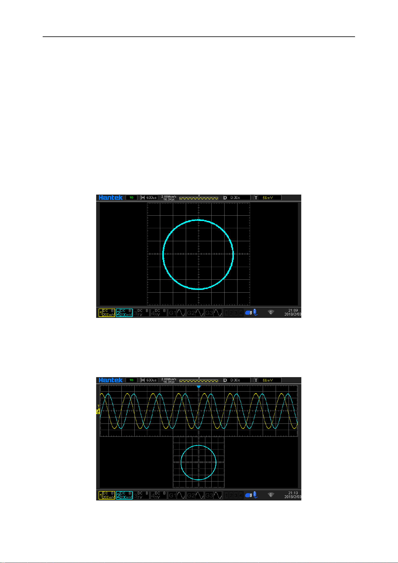
Test example: measure the phase difference between the input signals of the two
channels.
1. Connect a sinusoidal signal to CH1, and then connect a sinusoidal signal of the
same frequency, same amplitude and 90 ° phase difference to CH2.
2. Press the AutoScale key and adjust the vertical displacement of the CH1 and CH2
channels to 0 V.
3. After selecting the display mode as XY mode, turn the horizontal time base knob and
adjust the sampling rate appropriately to get better Lissajous graphics for better obser-
vation and measurement.
4. Adjust the vertical voltage scale of CH1 and CH2 to make the signal easy to observe.
At this point, you should get the circle shown in the figure below.
5. Observe the measurement results in the figure above, and according to the phase
difference measurement principle diagram, you can get A / B (C / D) = 1, that is, the
phase difference angle between the two channel input signals is θ = ± arcsin1 = 90 °.
XY dual window display mode
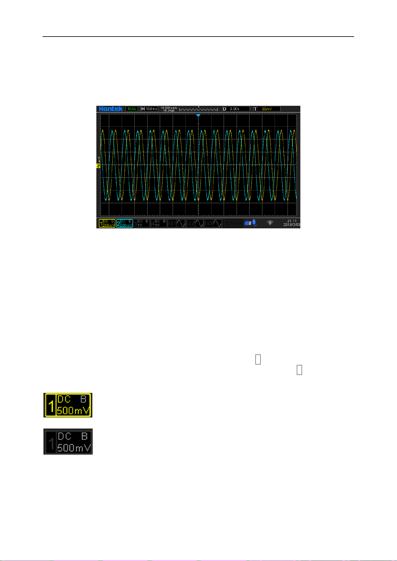
DPO6000, MPO6000 Series Digital Fluorescent Oscilloscope Product Manual V1.3
32
Roll mode
In this mode, the waveform scrolls from right to left to refresh the display. The adjust-
ment range of the horizontal gear is 100ms to 100s.
Note: When scroll mode is turned on, "Horizontal Shift", "Dual Window Mode", "Protocol
Decoding", "Pass / Fail Test", "Segment Acquisition", "Persistence Time", and "Trigger-
ing Oscilloscope" have no effect.
Vertical control system
Enable analog channel
The DPO6000 / MPO6000 series provides 4 analog input channels CH1-CH4. The ver-
tical system setting method of the 4 analog channels is exactly the same. This chapter
uses CH1 as an example to introduce the vertical system setting method. After con-
necting a signal to the channel connector of CH1, press the 1 button on the front panel.
The CH1 indicator lights up to indicate that CH1 is turned on. Press the 1 button again.
The CH1 indicator turns off to indicate that CH1 is turned off.
Channel open
Channel close
Channel coupling
Setting the coupling mode can filter out unwanted signals. For example: the measured
signal is a square wave signal with a DC offset.
DPO6000, MPO6000 Series Digital Fluorescent Oscilloscope Product Manual V1.3
33
➢ When the coupling method is DC: both the DC and AC components contained in
the signal under test can pass.
➢ When the coupling mode is AC: The DC component contained in the measured
signal is blocked.
➢ When the coupling method is ground: the DC and AC components contained in the
signal under test are blocked.
Press 1-> Coupling, and use to select the desired coupling method (default is DC). The
current coupling mode will be displayed in the channel status label at the bottom of the
screen. The user can also press the F1 [V0] key continuously to switch the coupling
mode.
Show icon description:
Channel coupling method is AC.
Channel coupling method is DC.
Channel coupling method is GND.
Bandwidth limitation
DPO6000 / MPO6000 series oscilloscopes support bandwidth limiting functions. Setting
a bandwidth limit can reduce noise in the displayed waveform. For example: the meas-
ured signal is a pulse signal containing high frequency oscillation. When the bandwidth
limit is turned off, high-frequency components contained in the signal under test can
pass. When the bandwidth limit is set to 20 MHz, the high-frequency components con-
tained in the signal under test are attenuated.
Press the 1 key and press the F2 key continuously to switch the bandwidth limit state.
The default is off, and a gray B is displayed in the channel menu. When the bandwidth
limit is turned on, the character B is displayed in the corresponding channel status label
at the bottom of the screen.
Note: Bandwidth limitation reduces or eliminates high-frequency components in the
signal while reducing noise.
Show icon description:
Channel is full bandwidth
Channel opens 20M bandwidth limit
DPO6000, MPO6000 Series Digital Fluorescent Oscilloscope Product Manual V1.3
34
Waveform inversion
Press 1-> Invert to turn the waveform inversion on or off. When the waveform inversion
is turned off, the waveform is displayed normally; when the waveform inversion is
turned on, the waveform voltage value is inverted (as shown in the figure below).
Inverted Off Inverted On
Probe ratio
The DPO6000 / MPO6000 series allows the user to manually set the probe attenuation
ratio. Press 1-> Probe; use to select the required probe ratio. For details, refer to the
“Technical Specifications” of the oscilloscope.
Vertical scale
The vertical scale, that is, the voltage value represented by each scale in the vertical
direction of the display screen, is usually expressed as V/div. Press 1. Rotate the verti-
cal SCALE to adjust the vertical scale. You can see that the size of the displayed wave-
form changes. Turn clockwise to decrease the scale and turn counterclockwise to in-
crease the scale. When adjusting the vertical scale, the scale information in the chan-
nel status label at the bottom of the screen changes in real time. The adjustment range
of the vertical scale is related to the currently set probe ratio. By default, the probe ratio
is X1, and the vertical scale can be adjusted from 500uV/div to 10V/div. There are two
ways to adjust the vertical scale: “coarse” and “fine”. You can switch the adjustment
mode by pressing the CH1 range.
➢ Coarse adjustment (counterclockwise as an example): Set the vertical scale by 1-2-
5 steps, that is, 500uV/div, 1mV/div, 2mV/div, 5mV/div, 10mV/div, 20mV/div,
50mV/div, 100mV/div ... 10V/div.
➢ Fine adjustment: further adjust the vertical scale in a smaller range to improve the
vertical resolution. If the amplitude of the input waveform is slightly larger than the
full scale in the current scale, and the amplitude displayed by the waveform of the
next gear is slightly lower, you can use fine adjustment to improve the waveform
display amplitude to facilitate observation of signal details.
DPO6000, MPO6000 Series Digital Fluorescent Oscilloscope Product Manual V1.3
35
Note: "Coarse adjustment" and "Fine adjustment" can be selected not only through the
amplitude scale menu, but also by pressing the vertical voltage scale quickly.
Analog channel delay setting
When using an oscilloscope for actual measurements, the propagation delay of the
probe cable may introduce large errors (zero drift). DPO6000 / MPO6000 series oscil-
loscopes allow users to set a delay time to correct the zero offset of the corresponding
channel. Zero offset is defined as the offset of the intersection of the waveform and the
trigger level line relative to the trigger position, as shown in the figure below.
Zero Offset
Delay correction. Turn the multi-function knob V0 to set the required delay correction
time. This parameter can be set from -100ns to 100ns. Press the multi-function knob to
restore the delay time to 0.00s.
Trigger system
Trigger can be understood as an event (or action); for example, the action of pressing
the shutter when taking a picture is a trigger, which is an event that starts the camera to
record an image. For an oscilloscope, the waveform (sampling data) will be recorded
after the trigger condition is met and displayed on the screen. When a digital oscillo-
scope is working, whether or not the instrument triggers steadily, it always acquires
waveforms continuously, but only stable triggers have a stable display. The trigger
module ensures that each time-based scan or acquisition starts from a user-defined
trigger condition, that is, each scan is synchronized with the acquisition, and the cap-
tured waveforms overlap to display a stable waveform.
The trigger setting should be based on the characteristics of the input signal, so the us-
er should have some knowledge of the signal under test in order to quickly capture the
required waveform. This oscilloscope provides a variety of trigger types, which is con-
venient for users to pay attention to the waveform details of interest.
The trigger determines when the oscilloscope starts acquiring data and displaying the
waveform. Once the trigger is set up properly, the oscilloscope can convert unstable
DPO6000, MPO6000 Series Digital Fluorescent Oscilloscope Product Manual V1.3
36
displays or blank screens into meaningful waveforms. Here are some basic concepts of
triggers.
Trigger source
Press the data source in the Trig Menu-> in the trigger control area on the front panel
to select the required trigger data source. Analog channels CH1-CH4, digital channels
D1.0-D1.3, D2.0-D2.3, D3.0-D3.3, D4.0-D4.3 can all be used as trigger data sources.
➢ Analog channel input:
The input signals of analog channels CH1-CH4 can all be used as trigger data sources.
If the selected trigger source channel is not turned on, it is regarded as an invalid trig-
ger.
➢ Digital channel input:
Only the digital channel connected to the oscilloscope can be used as the trigger data
source. [Some trigger methods cannot be selected-such as slope, video, window, under
Amp, etc.].
Acquisition process
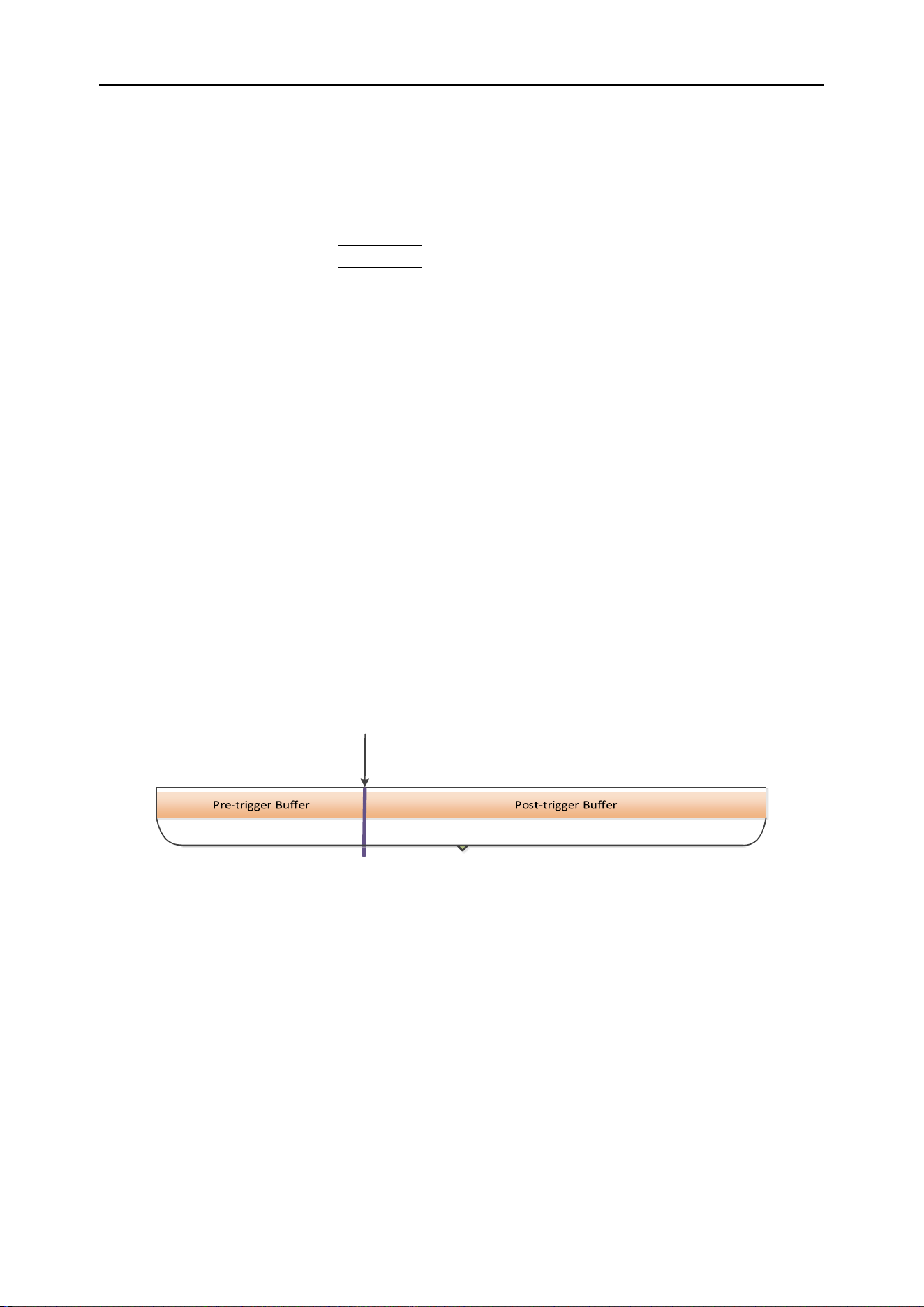
The following is a schematic diagram of the acquisition process. To facilitate under-
standing of trigger events, the acquisition memory can be divided into pre-trigger
memory and post-trigger memory.
Trigger Event
Waveform acquisition storage area
After the oscilloscope starts running, the oscilloscope stores the acquired data in the
trigger memory area. After the acquisition is completed, the oscilloscope will start to
search for trigger conditions; during the search for the trigger, the data collected by the
oscilloscope will continue to be stored in the pre-trigger storage area (new data will
continue to overwrite the existing data). Post-trigger store.
Trigger mode
Automatic mode allows free running acquisitions without a valid trigger. This mode al-
lows untriggered sweep waveforms to occur at a time base setting of 100ms/div or
slower. When the oscilloscope detects a valid trigger condition, it completes a triggered
acquisition. When the oscilloscope detects that there is no valid trigger condition, a

DPO6000, MPO6000 Series Digital Fluorescent Oscilloscope Product Manual V1.3
37
non-trigger acquisition is completed.
Normal mode will update the displayed waveform only if the oscilloscope has a valid
trigger. The oscilloscope will display the original waveform before replacing it with a
new waveform. Use Normal mode only when you want to see a valid trigger waveform.
When using this mode, the oscilloscope displays waveforms only after the first trigger.
Single Trigger Only when the oscilloscope has a valid trigger, it will stop after acquisi-
tion. To perform a single acquisition, press the Single button.
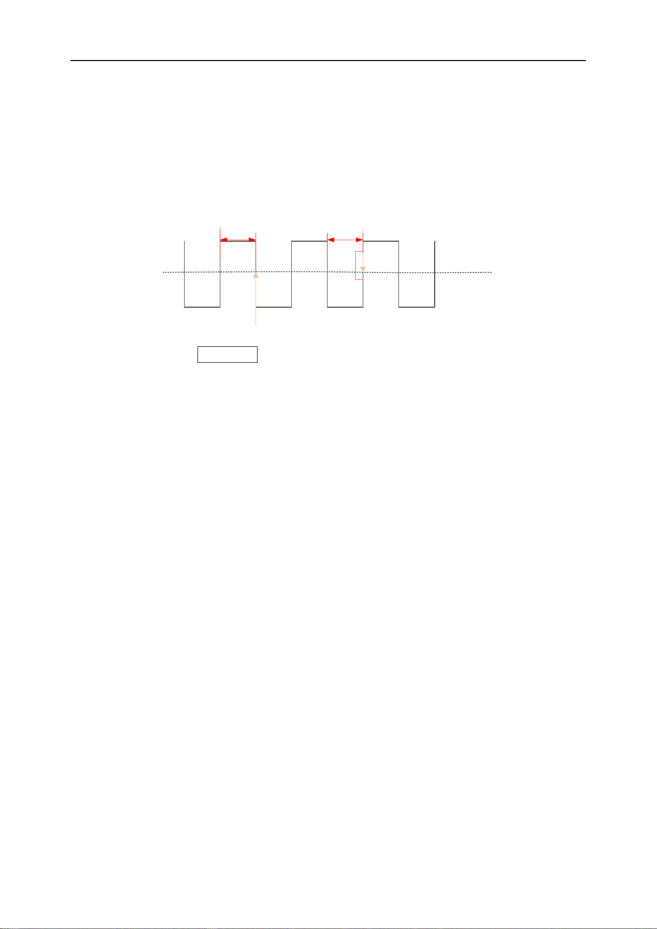
Trigger holdoff
Press the TrigMenu button to open the trigger menu and press the Hysteresis soft key.
The trigger holdoff function can be used to generate stable and complex waveforms
(such as AM columns) for display. "Holding off" refers to the time difference between
the oscilloscope detecting one trigger and preparing to detect another trigger. During
holdoff, the oscilloscope will not trigger. For a pulse train, you can adjust the holdoff
time so that the oscilloscope triggers only on the first pulse in the train.
Trigger level
Trigger holdoff Trigger holdoff
Trigger point The next trigger point
Trigger type
DPO6000 / MPO6000 series oscilloscopes have up to 16 trigger functions, as follows:
(1) Edge trigger
(2) Pulse trigger
(3) Video trigger
(4) Slope trigger
(5) Overtime trigger
(6) Window trigger
(7) Pattern trigger
(8) Interval trigger
(9) Under Amp trigger

DPO6000, MPO6000 Series Digital Fluorescent Oscilloscope Product Manual V1.3
38
(10) Delay trigger
(11) Setup/Hold trigger
(12) UART trigger [optional]
(13) LIN triggering [optional]
(14) CAN trigger [optional]
(15) SPI triggering [optional]
(16) IIC trigger [optional]
Edge trigger
Edge trigger types identify triggers by looking for a specified edge (rising, falling, rising,
or falling) and voltage level on the waveform.
Rising edge Falling edge
Trigger point Trigger point
Trigger level
Press the front panel Trig Menu button to open the trigger function menu.
[Type] Select the edge and press V0 to confirm.
[Data source] Select CH1~CH4 or LA as the trigger source.
Note: LA must be inserted when LA is used as the trigger source.
[Slope] Select the required triggering edge [rising edge, falling edge, double edge], and
press V0 to confirm.
[Mode] Select the acquisition mode [Auto, Normal] and press V0 to confirm.
[50%] Set the trigger level to the vertical midpoint of the peak-to-peak value of the trig-
ger signal. The trigger level value is displayed in the upper right corner of the screen.
[Holdoff] Set the holdoff time.
Trigger level knob: The analog channel can modify the trigger level value. The trigger
mark moves up and down with the rotation of the knob. Turn the trigger level knob to
adjust the trigger level to obtain a stable trigger.
Digital channel: You can change the trigger threshold of the digital channel by setting
the threshold voltage.
Note: Pressing the Auto Scale button will set the trigger type to edge trigger and the
DPO6000, MPO6000 Series Digital Fluorescent Oscilloscope Product Manual V1.3
39
trigger slope to rising edge.
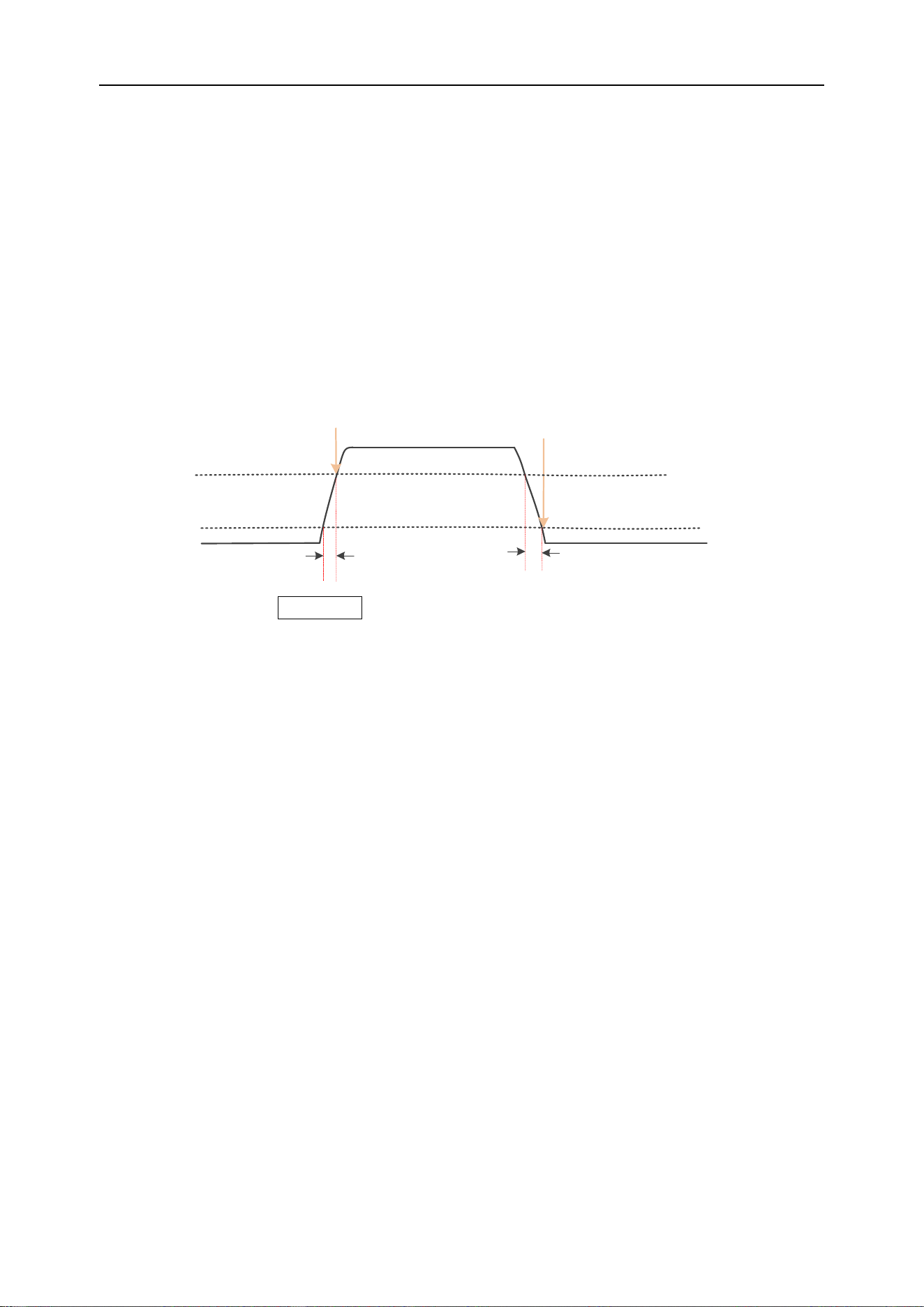
Pulse width trigger
Pulse width trigger sets the oscilloscope to trigger on a positive or negative pulse of a
specified width. You can set the trigger source, polarity (positive pulse width, negative
pulse width), limit conditions, and pulse width in this menu.
Trigger point
Trigger level
Positive pulse width Negative pulse width
Trigger point
Press the front panel Trig Menu button to enter the trigger function menu.
[Type] Select the pulse width and press V0 to confirm.
[Data source] Select CH1~CH4 or LA as the trigger source.
Note: LA must be inserted when LA is used as the trigger source.
[Polarity] Select the positive or negative polarity of the trigger.
[When] Select the trigger conditions [>, <, =, ≠], And press V0 to confirm.
> [Greater than the set time value]: When the positive or negative pulse width of the
input signal is greater than the set pulse width, it can be triggered (pulse width error is
5%).
< [Smaller than the set time value]: When the positive or negative pulse width of the
input signal is smaller than the set pulse width, it can be triggered (pulse width error is
5%).
= [Equal to the set time value]: When the positive or negative pulse width of the input
signal is equal to the set pulse width, it can be triggered (pulse width error is 5%).
≠ [Not equal to the set time value]: When the positive or negative pulse width of the
input signal is not equal to the set pulse width, it can be triggered (pulse width error is
5%).
[Width] Set the pulse width time from 8ns to 10s.
[50%] Set the trigger level to the vertical midpoint of the peak-to-peak value of the trig-
ger signal. The trigger level value is displayed in the upper right corner of the screen.
[Mode] Select the acquisition mode [Auto, Normal] and press V0 to confirm.
[Holdoff] Set the holdoff time.

DPO6000, MPO6000 Series Digital Fluorescent Oscilloscope Product Manual V1.3
40
Trigger level knob: The analog channel can modify the trigger level value. The trigger
mark moves up and down with the rotation of the knob. Turn the trigger level knob to
adjust the trigger level to obtain a stable trigger.
Digital channel: You can change the trigger threshold of the digital channel by setting
the threshold voltage.
Video trigger
Video triggers can be used to capture the complex waveforms of most standard analog
and HD video signals. The trigger circuit detects the vertical and horizontal intervals of
the waveform and generates a trigger based on the selected video trigger setting. This
series of oscilloscopes support NTSC (National Television Stands Committee) and PAL
etc.
Press the Trig Menu button on the front panel to enter the trigger function menu.
[Type] Select the video and press V0 to confirm.
[Data source] Select CH1~CH4 as the trigger source.
[Standard] Select the required video standard. The video standards supported by this
series of oscilloscopes are: NTSC, PAL, HDTV720p, HDTV1080p, and HDTV1080i.
[Sync] Select the video trigger type [scan line, line number, odd field, even field, all
fields].
Scan line: trigger on the first line found.
Line number: For NTSC and PAL / SECAM video standards, trigger on the specified
line of "odd field" or "even field".
Note: When this synchronous trigger mode is selected, the line number can be
changed in the “Number of Lines” menu item in steps of 1. The number of lines can be
set from 1 to 525 [NTSC], 1 to 625 [PAL], 1 to 750 [720P], and 1 to 1125 [1080P /
1080i].
Odd field: Trigger on the rising edge of the first tooth pulse in the "odd field".
Even field: Trigger on the rising edge of the first tooth pulse in the "even field".
All fields: Trigger on the rising edge of the first tooth pulse in the odd / even fields.
[Line Number] Rotate V0 to set the number of video lines: 1 to 525 [NTSC], 1 to 625
[PAL], 1 to 750 [720P], 1 to 1125 [1080P / 1080i].
[Polarity] Select the video polarity [Positive polarity, Negative polarity].
[Mode] Select the acquisition mode [Auto, Normal] and press V0 to confirm.
[Holdoff] Set the holdoff time.
DPO6000, MPO6000 Series Digital Fluorescent Oscilloscope Product Manual V1.3
41
Trigger level knob: The analog channel can modify the trigger level value. The trigger
mark moves up and down with the rotation of the knob. Turn the trigger level knob to
adjust the trigger level to obtain a stable trigger.
Slope trigger
Slope trigger sets the positive or negative slope trigger of the oscilloscope from one
level to another within a specified time.
As shown in the figure below, we define the time difference between the two points
where the high and low trigger levels intersect with the rising (falling) edge of the wave-
form as the positive (negative) slope time.
Trigger point
Trigger level 1
Trigger level 2
Positive slope time
Trigger point
Negative slope time
Press the front panel Trig Menu button to open the trigger function menu.
[Type] Select the slope and press V0 to confirm.
[Data source] Select CH1~CH4 as the trigger source.
[Slope] Select the required triggering edge [rising edge or falling edge].
[Level] Select low level [V2] or high level [V1], then turn the trigger level knob to adjust
the vertical position of the high [low] level to obtain the required slope time T. The cor-
responding displacement information changes in real time and is displayed in the status
bar in the upper right corner of the screen.
[When] Set the trigger condition (>, <, =, ≠), press V0 to confirm.
> (Greater than the set time value): It can be triggered when the slope time of the ris-
ing or falling edge of the input signal is greater than the set slope time (pulse width er-
ror is 5%).
< (Smaller than the set time value): It can be triggered when the slope time of the ris-
ing or falling edge of the input signal is smaller than the set slope time (pulse width er-
ror is 5%).
= (Equal to the set time value): It can be triggered when the slope time of the rising or
falling edge of the input signal is equal to the set slope time (pulse width error is 5%).
≠(Not equal to the set time value): It can be triggered when the slope time of the rising
or falling edge of the input signal is not equal to the set slope time (pulse width error is
5%).
DPO6000, MPO6000 Series Digital Fluorescent Oscilloscope Product Manual V1.3
42
[Time] Set slope time reference (8ns~10s), the slope time is the horizontal time interval
between the intersection of the high and low levels and the rising or falling edge of the
waveform.
[Mode] Select the acquisition mode [Auto, Normal] and press V0 to confirm.
[Holdoff] Set the hysteresis time.
Trigger level knob: The analog channel can modify the trigger level value. The trigger
mark moves up and down with the rotation of the knob. Turn the trigger level knob to
adjust the trigger level to obtain a stable trigger.
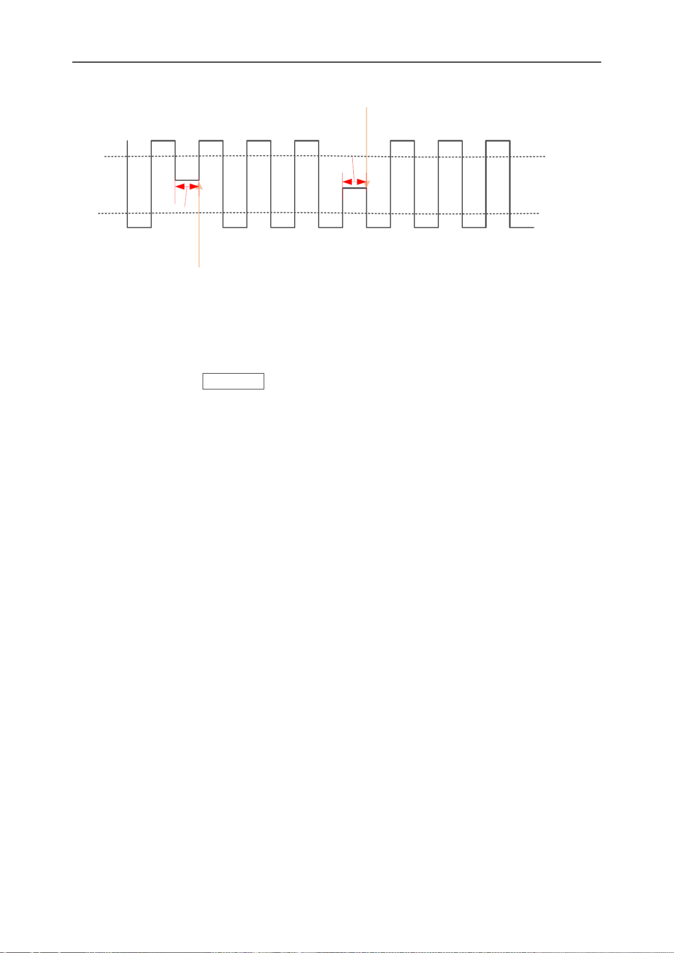
Overtime trigger
Trigger when the time interval (△T) from the rising edge (or falling edge) of the input
signal passes the trigger level to the end of the adjacent falling edge (or rising edge)
pass the trigger level is greater than the set overtime period. As shown below:
Trigger point
Trigger level
Overtime time
Overtime time
Trigger point
Press the front panel Trig Menu button to open the trigger function menu.
[Type] Select overtime and press V0 to confirm.
[Data source] Select CH1~CH4 or LA as the trigger source.
Note: LA must be inserted when LA is used as the trigger source.
[Polarity] Select the positive or negative polarity of the trigger.
[Time] Set the pulse width time (8ns~10s).
[50%] Set the trigger level to the vertical midpoint of the peak-to-peak value of the trig-
ger signal. The trigger level value is displayed in the upper right corner of the screen.
[Mode] Select the acquisition mode (auto, normal) and press V0 to confirm.
[Holdoff] Set the holdoff time.
Trigger level knob: The analog channel can modify the trigger level value. Trigger the
mark and move up and down with the knob. Turn the trigger level knob to adjust the
DPO6000, MPO6000 Series Digital Fluorescent Oscilloscope Product Manual V1.3
43
trigger level to obtain a stable trigger.
Digital channel: You can change the trigger threshold of the digital channel by setting
the threshold voltage.
Window trigger
Window triggering provides high and low trigger levels. When the input signal passes
the high or low trigger level, the oscilloscope triggers.
Horizontal trigger position
Trigger point1【high level】
Trigger point 2【low level】
If both the high and low levels are within the waveform range, the waveform is triggered
on the rising or falling edge at the same time.
If the high level is within the waveform range and the low level is outside the waveform
range, the waveform will only trigger on the rising edge.
If the high level is outside the waveform range and the low level is within the waveform
range, the waveform will only trigger on the falling edge.
Press the front panel Trig Menu button to open the trigger function menu.
[Type] Select the window and press V0 to confirm.
[Data source] Select CH1~CH4 as the trigger source.
[Level] Enable the high / low level setting function, continue to press this soft key, se-
lect low level (V2) or high level (V1), and then turn the trigger level knob to adjust the
vertical position of the high (low) level. The corresponding displacement information
changes in real time and is displayed in the status bar in the upper right corner of the
screen.
[Mode] Select the acquisition mode (auto, normal) and press V0 to confirm.
[Holdoff] Set the holdoff time.
Trigger level knob: The analog channel can modify the trigger level value. Trigger the
mark and move up and down with the knob. Turn the trigger level knob to adjust the
trigger level to obtain a stable trigger.
Pattern trigger
Identify trigger conditions by looking for specific patterns. This pattern is a logical AND

DPO6000, MPO6000 Series Digital Fluorescent Oscilloscope Product Manual V1.3
44
and OR combination between channels. Each channel can have a value of high (1),
low (0), or inactive (X). In the pattern trigger mode, the oscilloscope will compare the
actual pattern of the channel with the preset pattern, and trigger on the last channel
that is the same as the preset pattern (the pattern is true). If the pattern of each chan-
nel is fixed or the pattern of all channels is set to "Invalid", the oscilloscope will not trig-
ger.
CH1~CH4 & LA1~LA4
Logical value H,L,X
CH1
LA4.3
Pattern trigger output
Press the front panel Trig Menu button to open the trigger function menu.
[Type] Select the code type and press V0 to confirm.
[Data source] Select CH1~CH4 or LA as the trigger source.
Note: LA must be inserted when LA is used as the trigger source.
[Current channel pattern] Set the current channel pattern. Press V0 to confirm. The
preset pattern is displayed in the upper left corner of the screen.
1: Set the channel pattern to "H", that is, the level is higher than the trigger level of the
channel.
0: Set the channel pattern to "L", that is, the level is lower than the trigger level of the
channel.
X: Set the channel pattern to "X", that is, this channel is not used as part of the pattern.
[Mode] Select the acquisition mode (auto, normal) and press V0 to confirm.
[Holdoff] Set the holdoff time.
Trigger level knob: Press the channel button first and then move the trigger level knob
to modify the trigger level value of the corresponding channel. Trigger the mark and
move up and down with the knob. Turn the trigger level knob to adjust the trigger level
to obtain a stable trigger. For example, set the CH1 trigger level. Press soft key CH1 to
use the trigger level to modify the level.
Digital channel: You can change the trigger threshold of the digital channel by setting
the threshold voltage.
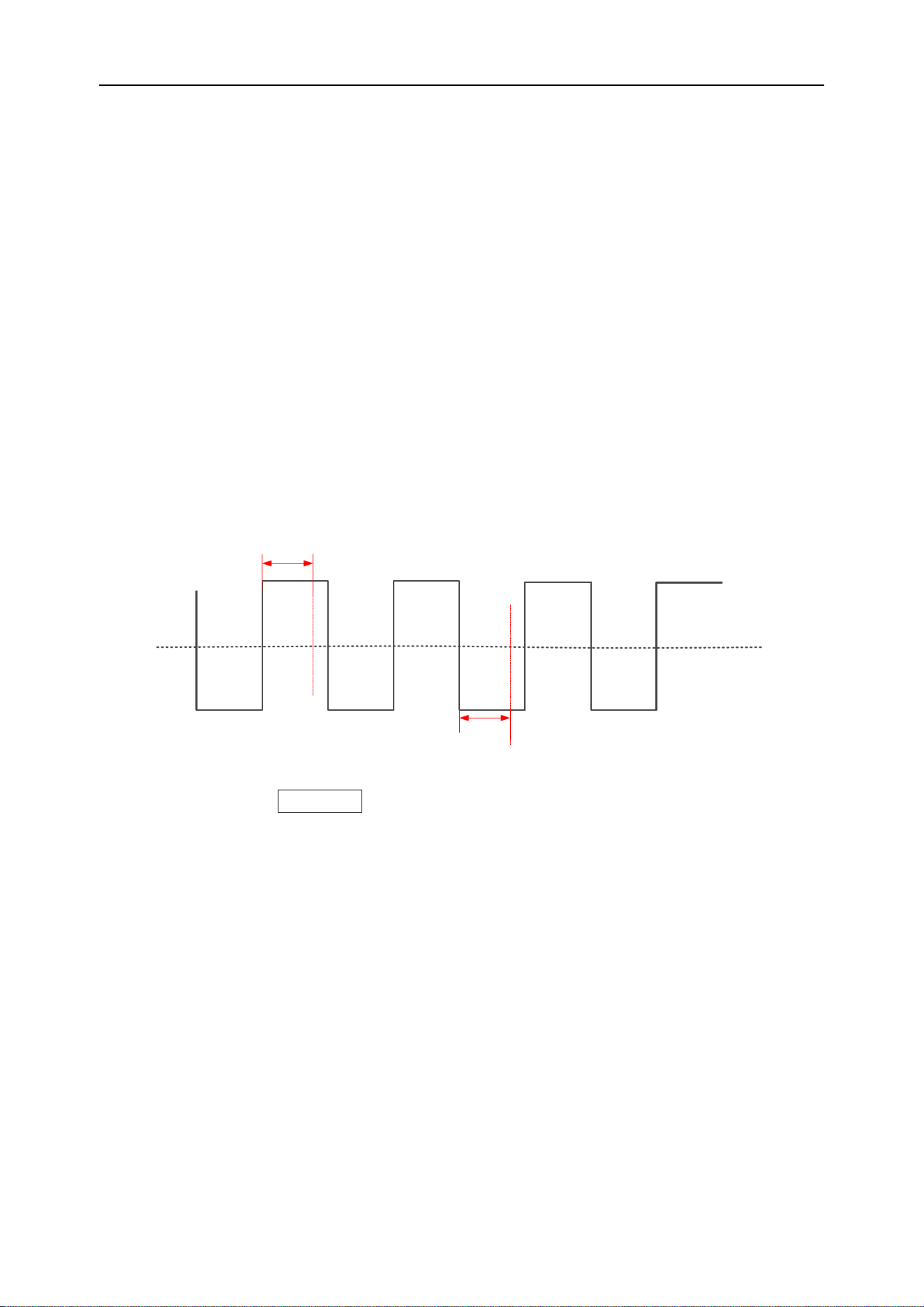
Interval trigger
Triggered when the interval between two consecutive rising edges (or falling edges)

DPO6000, MPO6000 Series Digital Fluorescent Oscilloscope Product Manual V1.3
45
meets the set time condition (>, <, =, ≠).
Trigger point
Positive interval time Negative interval time
Trigger point
Trigger level
Press the front panel Trig Menu button to open the trigger function menu.
[Type] Select the interval and press V0 to confirm.
[Data source] Select CH1~CH4 or LA as the trigger source.
Note: LA must be inserted when LA is used as the trigger source.
[Slope] Select the positive or negative polarity of the trigger.
[When] Select the trigger condition (>, <, =, ≠), And press V0 to confirm.
> [Greater than the set time value]: It can trigger when the interval between two rising
or falling edges is greater than the set reference time (pulse width error is 5%).
< [Smaller than the set time value]: It can trigger when the interval between two rising
or falling edges is smaller than the set reference time (pulse width error is 5%).
= [Equal to the set time value]: It can trigger when the interval between two rising or
falling edges is equal to the set reference time (pulse width error is 5%).
≠ [Not equal to the set time value]: It can trigger when the interval between two rising
or falling edges is not equal to the set reference time (pulse width error is 5%).
[Time] Set the reference time (8ns~10s).
[Mode] Select the acquisition mode (auto, normal) and press V0 to confirm.
[Holdoff] Set the holdoff time.
Trigger level knob: The analog channel can modify the trigger level value. Trigger the
mark and move up and down with the knob. Turn the trigger level knob to adjust the
trigger level to obtain a stable trigger.
Digital channel: You can change the trigger threshold of the digital channel by setting
the threshold voltage.
Under Amp trigger
Under Amp triggering is used to trigger pulses that cross one trigger level but not an-
other trigger level, as shown in the figure below:
DPO6000, MPO6000 Series Digital Fluorescent Oscilloscope Product Manual V1.3
46
Trigger point
Trigger point
Trigger level 1
Trigger level 2
Positive under
Amp pulse
Negative under
Amp pulse
➢ Positive runt: The pulse crosses the low level but not the high level.
➢ Negative runt: The pulse crosses the high level but not the low level.
Set Under Amp trigger:
Press the front panel Trig Menu button to open the trigger function menu.
[Type] Select runt and press V0 to confirm.
[Data source] Select CH1~CH4 as the trigger source.
[Polarity] Select the positive or negative polarity of the trigger.
[When] Set the trigger condition (>, <, =, ≠) and press V0 to confirm.
> [Greater than the set width value]: It can be triggered when the negative pulse width
or the positive pulse width is greater than the set width (pulse width error is 5%).
< [Smaller than the set width value]: It can be triggered when the negative pulse width
or the positive pulse width is smaller than the set width (pulse width error is 5%).
= [Equal to the set width value]: It can be triggered when the negative pulse width or
the positive pulse width is equal to the set width (pulse width error is 5%).
≠ [Not equal to the set width value]: It can be triggered when the negative pulse width
or the positive pulse width is not equal to the set width (pulse width error is 5%).
[Width] Set the reference time (8ns~10s) for the negative pulse width (or positive
pulse width) when the pulse crosses the high level but does not cross the low level (or
crosses the low level but does not cross the high level).
[Level] Enable the high / low level setting function, continue to press this soft key, se-
lect low level (V2) or high level (V1), and then turn the trigger level knob to adjust the
vertical position of the high (low) level. The corresponding displacement information
changes in real time and is displayed in the status bar in the upper right corner of the
screen.
[Mode] Select the acquisition mode (auto, normal) and press V0 to confirm.

DPO6000, MPO6000 Series Digital Fluorescent Oscilloscope Product Manual V1.3
47
[Holdoff] Set the holdoff time.
Trigger level knob: You can modify the trigger level value. Trigger the mark and move
up and down with the knob. Turn the trigger level knob to adjust the trigger level to ob-
tain a stable trigger.
Delay trigger
Under the delay trigger type, the user needs to set trigger data source 1 and data
source 2. When the time difference between the edge (edge 1) set by data source 1
and the edge (edge 2) set by data source 2 meet the preset time limit, the oscilloscope
triggers, as shown in the figure below.
Signal source 1
Delay time
Signal source 2
Note: Edge 1 and Edge 2 must be immediately adjacent edges.
Press the front panel Trig Menu button to open the trigger function menu.
[Type] Select the delay and press V0 to confirm.
[Data source 1] Select CH1~CH4 or LA as the trigger source.
Note: LA must be inserted when LA is used as the trigger source.
[Slope 1] Select the required triggering edge (rising or falling edge)
[Data source 2] Select CH1~CH4 or LA as the trigger source.
Note: LA must be inserted when LA is used as the trigger source.
[Slope 2] Select the required triggering edge (rising or falling edge)
[When] Set the trigger condition and press V0 to confirm.
> [Greater than the set width value]: Trigger when the time difference between the set
edges is greater than the set width (pulse width error is 5%).
< [Smaller than the set width value]: Trigger when the time difference between the set
edges is smaller than the set width (pulse width error is 5%).
= [Equal to the set width value]: Trigger when the time difference between the set
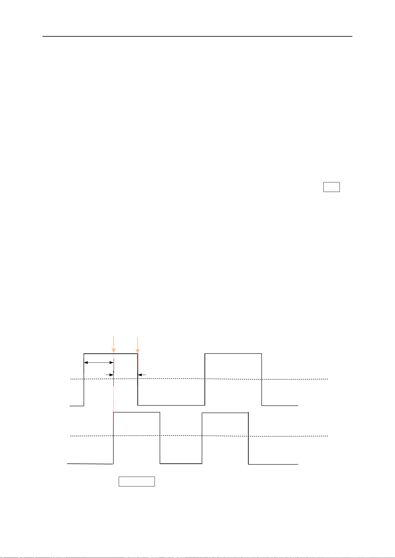
DPO6000, MPO6000 Series Digital Fluorescent Oscilloscope Product Manual V1.3
48
edges is equal to the set width (pulse width error is 5%).
≠ [Not equal to the set width value]: Trigger when the time difference between the set
edges is not equal to the set width (pulse width error is 5%).
[Width] Set the reference value of the time difference between the edges set by the
two data sources (8ns~10s).
[Mode] Select the acquisition mode (auto, normal) and press V0 to confirm.
[Holdoff] Set the holdoff time.
Trigger level knob: Press the channel button first and then move the trigger level knob
to modify the trigger level value of the corresponding channel. Trigger the mark and
move up and down with the knob. Turn the trigger level knob to adjust the trigger level
to obtain a stable trigger. For example, set the CH1 trigger level. Press soft key CH1 to
use the trigger level to modify the level.
Digital channel: You can change the trigger threshold of the digital channel by setting
the threshold voltage.
Setup/Hold trigger
Under the setup/hold trigger type, the user needs to set the data signal line and clock
signal line. The setup time starts when the data signal crosses the trigger level and
ends when the specified clock edge arrives; the hold time starts when the specified
clock edge arrives and ends when the data signal crosses the trigger level again (as
shown in the figure below). The oscilloscope will trigger when the setup time or hold
time is less than the preset time.
Data channel
Clock channel
Setup time trigger point
Hold time trigger point
Setup time
Hold time
Press the front panel Trig Menu button to open the trigger function menu.
[Type] Select Build Hold and press V0 to confirm.

DPO6000, MPO6000 Series Digital Fluorescent Oscilloscope Product Manual V1.3
49
[Data] Select CH1~CH4 or LA as the trigger source.
Note: LA must be inserted when LA is used as the trigger source.
[Data type] Select high level or low level.
[Clock] Select CH1~CH4 or LA as the trigger source of the clock channel.
Note: LA must be inserted when LA is used as the trigger source.
[Slope] Select the required triggering edge (rising edge or falling edge).
[Polarity] Select the hold type (establish or hold).
Setup: The time when the data is stable before the clock edge arrives.
Hold: The time when the data is stable after the clock edge arrives.
[Width] Set the setup time and hold time separately.
[Mode] Select the acquisition mode (auto, normal) and press V0 to confirm.
[Holdoff] Set the holdoff time.
Trigger level knob: Press the channel button first and then move the trigger level knob
to modify the trigger level value of the corresponding channel. Trigger the mark and
move up and down with the knob. Turn the trigger level knob to adjust the trigger level
to obtain a stable trigger. For example, set the CH1 trigger level. Press soft key CH1 to
use the trigger level to modify the level.
Digital channel: You can change the trigger threshold of the digital channel by setting
the threshold voltage.
UART trigger [optional]
UART bus is a serial communication method used for data transfer between computers
or between computers and terminals. The UART serial protocol transmits a character
as a frame of data, and its frame structure is composed of a 1-bit start bit, 5-8 bits data
bit, 1-bit check bit, and 1--2 bit stop bit.
Free bit
1/0 1/0 ... 1/0
Check
bit
Start bit
Data bit:5~8bits
Stop bit:1~2bits
Check bit:0~1bit
Its format is shown above. DPO6000 / MPO6000 series oscilloscope can trigger when it
detects the frame start, stop bit, data, parity error or data bit error of the UART signal.
Press the Trig Menu button on the front panel to enter the trigger function menu.
[Type] Select UART and press V0 to confirm.
[Data source] Select CH1~CH4 or LA as the trigger source.

DPO6000, MPO6000 Series Digital Fluorescent Oscilloscope Product Manual V1.3
50
Note: LA must be inserted when LA is used as the trigger source.
[Baud rate] Select the baud rate.
DPO6000 / MPO6000 series machines provide users with common baud rates as fol-
lows:
110
300
600
1200
2400
4800
9600
14400
19200
38400
57600
115200
230400
380400
460400
Custom
If the user finds the required baud rate in the table above, you can select Custom and
set your own baud rate.
[Custom] Users set their own baud rate {only available if you choose to customize this
menu}
[When] Set UART trigger conditions:
Start bit: When the UART start bit appears, trigger in the middle of the bit.
Stop bit: When the UART stop bit appears, it triggers in the middle of the bit. Regard-
less of the stop position 1, 1.5, 2 of the device under test, the machine will process it
according to 1 bit.
Data: The normal reception of data is completed, and the received UART data and us-
er-set data are equal to trigger at the stop bit.
Parity error: The normal reception of data is completed. When a parity error occurs in
the data, it is triggered at the stop bit.
Data bit error: When the data is checked at the stop bit of the start bit, it is triggered
when an error occurs.
[Idle level] The level value (level / high level) when the UART is idle. The default set-
ting is high level.
[Parity check] Set whether the measured UART data is checked (odd check, even
check or none).
[Data bits] Set the length of the UART data to be measured (5, 6, 7, 8 bits can be se-
lected).
[Data] The trigger data set by the user (only available when the trigger type is data).
[Mode] Select the acquisition mode (auto, normal) and press V0 to confirm.
[Holdoff] Set the holdoff time.
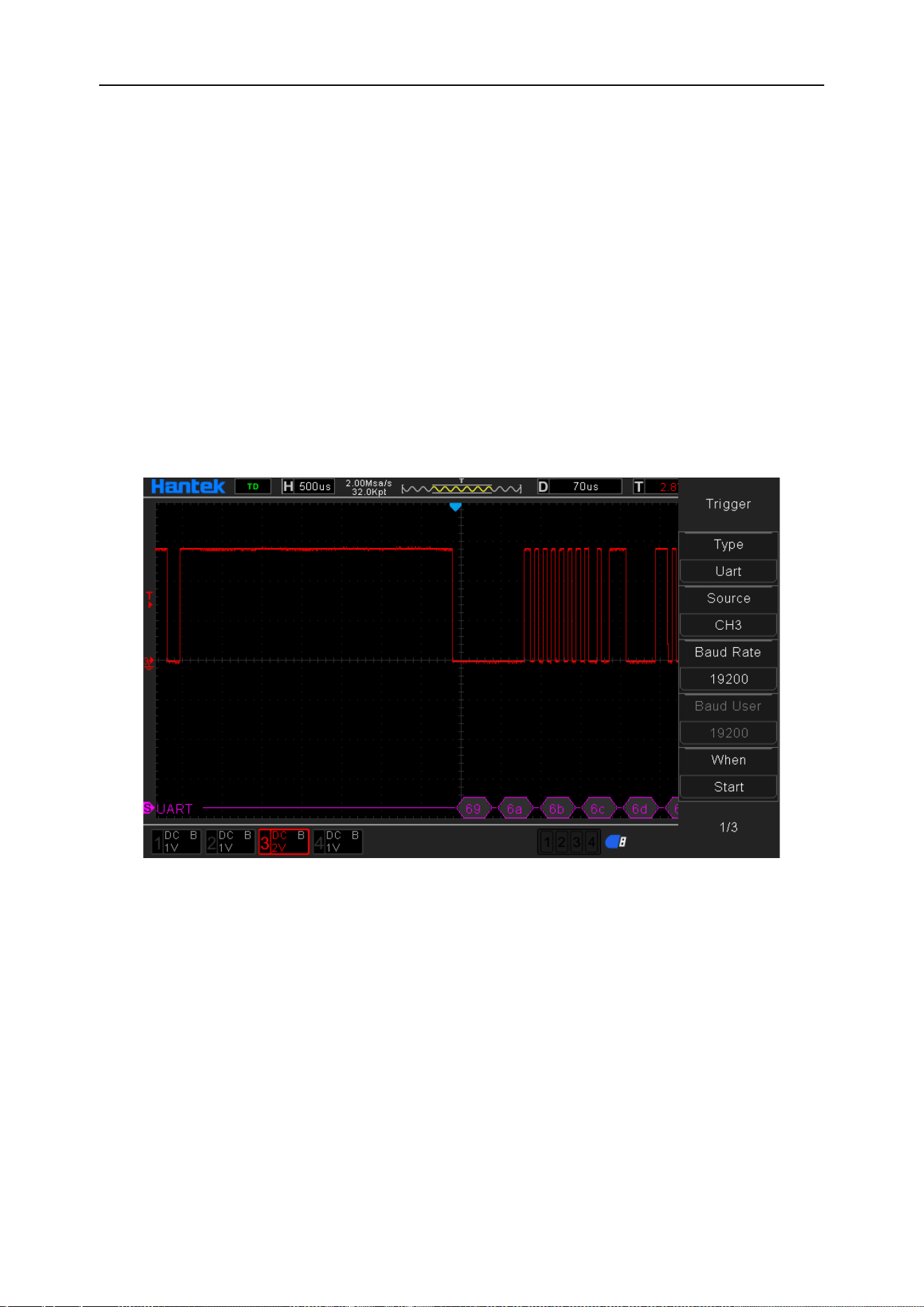
DPO6000, MPO6000 Series Digital Fluorescent Oscilloscope Product Manual V1.3
51
[Decode] Switch the decoding function.
[Label position] The position where the decoded data is drawn on the screen (only
available when the decode function is turned on).
[Table] Data recording mode.
Trigger level knob: The analog channel can modify the trigger level value. Trigger the
mark and move up and down with the knob.
Digital channel: You can change the trigger threshold of the digital channel by setting
the threshold voltage.
Trigger setting 1:
Data source: CH3; Baud rate: 19200; When: Start; Idle level: High; Parity: None; Data
bits: 8. Adjust the trigger level. The trigger result is displayed as follows:
Trigger setting 2:
Data source: CH3; Baud rate: 19200; When: Data; Idle level: High; Parity: None; Data
bits: 8; Data: 0 × 55. Adjust the trigger level. The trigger result is displayed as follows:
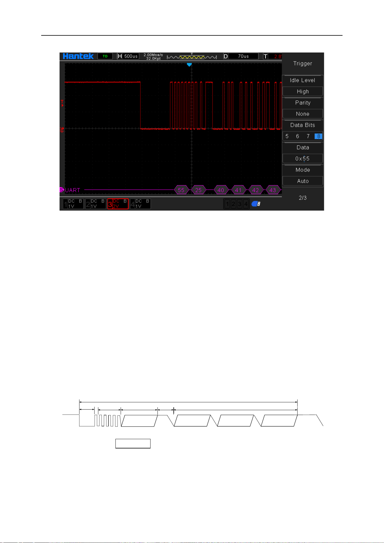
DPO6000, MPO6000 Series Digital Fluorescent Oscilloscope Product Manual V1.3
52
UART decoding explanation:
1. The decoded data is displayed in hexadecimal;
2. The decoded data shows purple;
3. When “?” Or “Please adjust the time base” appears, you need to adjust the time
base to get the decoding result.
LIN trigger [optional]
The LIN bus is a low-cost serial communication network defined for automotive distrib-
uted electronic systems. It is a supplement to other automotive multiplex networks such
as the controller area network (CAN). It is suitable for network bandwidth and perfor-
mance. Or applications where fault tolerance is not too demanding. The LIN bus is
based on the SCI (UART) data format and uses a single-master / multi-slave mode,
which is a special case in the UART.
The LIN signal message frame is displayed as follows:
Frame interval
Data 1 Data n Checksum
Response
Frame interval
Frame
Interval
synchronization
Identifier
Response interval
Press the front panel Trig Menu button to open the trigger function menu.
[Type] Select LIN and press V0 to confirm
[Data source] Select CH1~CH4 or LA as the trigger source.
Note: LA must be inserted when LA is used as the trigger source.

DPO6000, MPO6000 Series Digital Fluorescent Oscilloscope Product Manual V1.3
53
[Baud rate] Select the baud rate.
DPO6000 / MPO6000 series machines provide users with common baud rates as fol-
lows:
110
300
600
1200
2400
4800
9600
14400
19200
38400
57600
115200
230400
380400
460400
Custom
If the user finds the required baud rate in the table above, you can select Custom and
set your own baud rate.
[Custom] Users set their own baud rate {only available by selecting Customize this
menu}.
[When] Set LIN trigger conditions:
Interval field: The edge is triggered when the LIN gap ends.
Sync field: LIN sync field data completion trigger.
ID field: LINID field data reception completion trigger.
Sync Code error: trigger when LIN sync field data is received but the sync field data is
not equal to 0x55.
Identifier: Triggered when the LINID field data is received and the ID data is equal to
the ID set by the user.
ID and data: LIN data is received normally. ID and data are equal to the data set by the
user.
[Identifier] The identifier data when LIN is triggered.
[Data 1] Data when LIN is triggered.
[Data 2] Data when LIN is triggered.
[Data 3] LIN trigger data.
[Data 4] LIN trigger data.
[Idle level] The level value (level / high level) at the LIN frame interval. The default set-
ting is high level.
[Mode] Select the acquisition mode (auto, normal) and press V0 to confirm.
[Holdoff] Set the holdoff time.
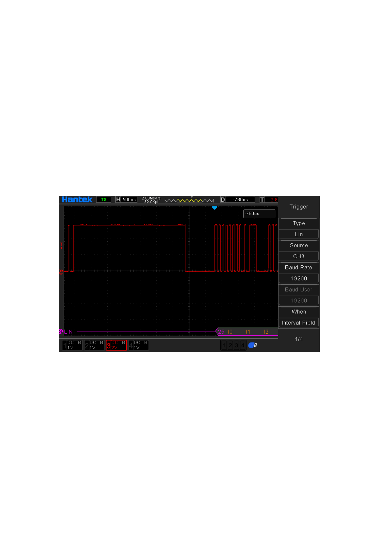
DPO6000, MPO6000 Series Digital Fluorescent Oscilloscope Product Manual V1.3
54
[Decode] Switch the decoding function.
[Label position] The position where the decoded data is drawn on the screen (only
available when the decode function is turned on).
[Table] Data recording mode.
Trigger level knob: The analog channel can modify the trigger level value. Trigger the
mark and move up and down with the knob.
Digital channel: You can change the trigger threshold of the digital channel by setting
the threshold voltage.
Trigger setting 1:
Data source: CH3; Baud rate: 19200; When: interval field; Idle level: High; Adjust the
trigger level.
Trigger setting 2:
Data source: CH3; Baud rate: 19200; When: identifier; Idle level: High; Adjust the trig-
ger level. The trigger result is shown below:
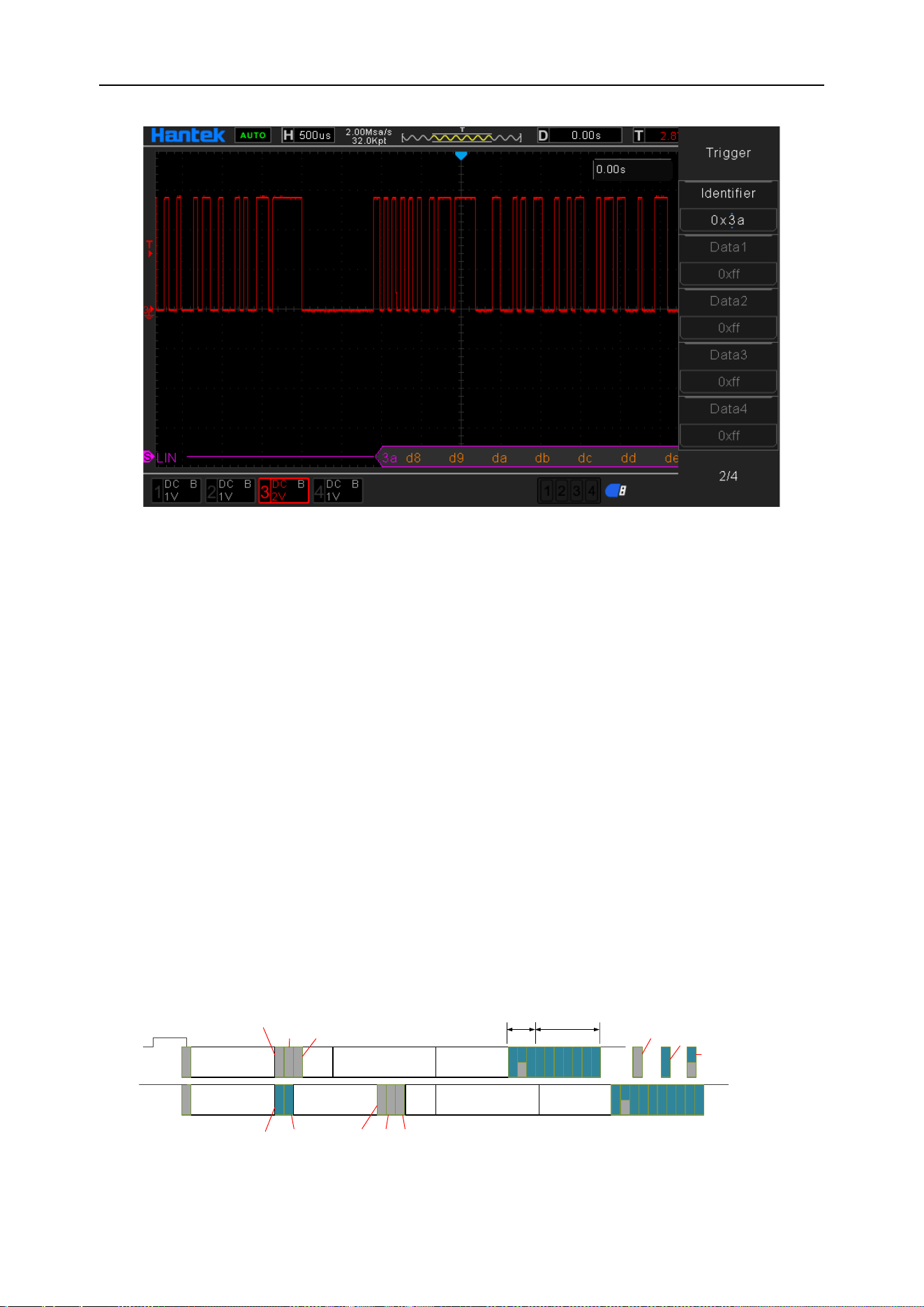
DPO6000, MPO6000 Series Digital Fluorescent Oscilloscope Product Manual V1.3
55
LIN decoding explanation:
1. Decoded data is displayed in hexadecimal;
2. The "Identifier" and "Checksum" display colors are purple, and the "Data" display
color is orange;
3. When "?" Appears, adjust the time base to get the decoding result;
4. In the LIN decoding result, the synchronous field "55" is not displayed.
CAN trigger [optional]
CAN is the abbreviation of Controller Area Network (CAN). It was developed by the
German company BOSCH, which is famous for R & D and production of automotive
electronics. Eventually it became the international standard (ISO 11898), which is the
most widely used internationally. Fieldbus one. In North America and Western Europe,
the CAN bus protocol has become the standard bus for automotive computer control
systems and embedded industrial control area networks, and it has the J1939 protocol
designed for large trucks and heavy industrial vehicles with CAN as the underlying pro-
tocol.
11 bits ID
DLC4
DATA 0~64
Check bit
11bits ID 18 bits ID
DLC4
DATA 0~64
Check bit
ACK DelimiterACK
RTR
IDE R0
SRR
IDE RTR R1 R0
dominant
recessive
Dominant/recessive

DPO6000, MPO6000 Series Digital Fluorescent Oscilloscope Product Manual V1.3
56
CAN trigger settings:
Press the front panel Trig Menu button to open the trigger function menu.
[Type] Select CAN and press V0 to confirm
[Data source] Select CH1~CH4 or LA as the trigger source.
Note: LA must be inserted when LA is used as the trigger source.
[Baud rate] Select the baud rate.
DPO6000 / MPO6000 series machines provide users with common baud rates as fol-
lows:
10000
20000
33300
50000
62500
83300
100000
125000
250000
500000
800000
1000000
Custom
If the user finds the required baud rate in the table above, you can select Custom and
set your own baud rate.
[Baud User] Users set their own baud rate {only available if you choose to customize
this menu}
[When] Set CAN trigger conditions:
Start bit: CAN triggers at the beginning of a frame.
Remote frame ID: Triggered when the CAN frame type is remote frame, the frame ID is
received, and the ID is equal to the user set value.
Data frame ID: Triggered when the CAN frame type is a data frame, the frame ID is re-
ceived, and the ID is equal to the value set by the user.
Frame ID: Triggered when CAN receives the frame ID and the ID is equal to the user
set value.
Frame ID and data: CAN data reception is complete, trigger when ID and data are
equal to the user set value.
Error frame: trigger when CAN error frame is detected.
All errors: error frame of CAN is detected, bit error, trigger when confirm error.
Acknowledge error: Ack error of CAN is triggered.
Overload frame: trigger when CAN overload frame is detected.
[Identifier] The identifier data when CAN is triggered.
[Data 1] Data when CAN is triggered.
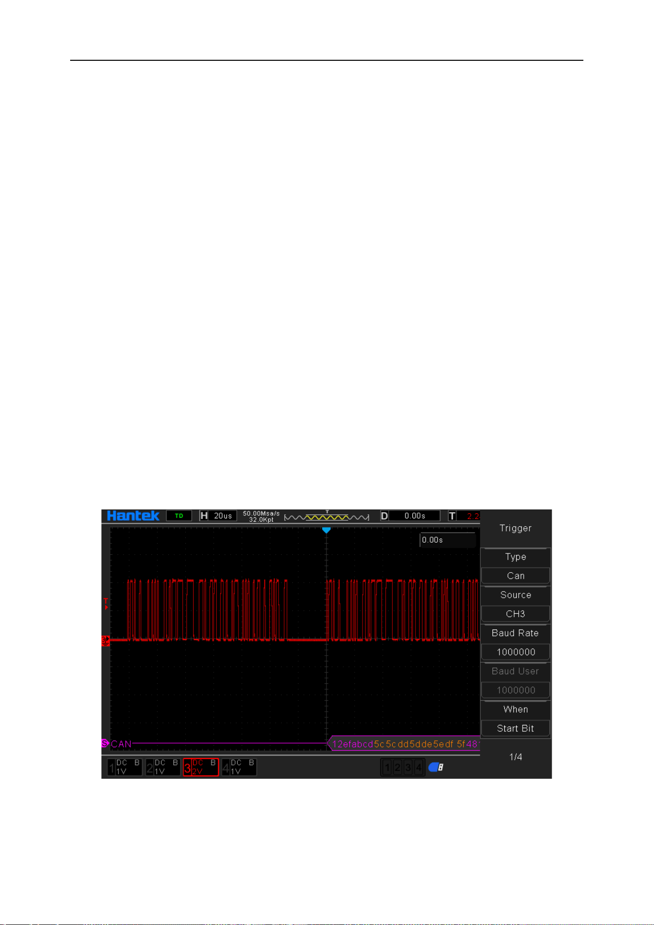
DPO6000, MPO6000 Series Digital Fluorescent Oscilloscope Product Manual V1.3
57
[Data 2] Data when CAN is triggered
[Data 3] Data when CAN is triggered
[Data 4] Data when CAN is triggered
[Idle level] The level value (level / high level) during the CAN frame interval. The de-
fault setting is: low level.
[Mode] Select the acquisition mode (auto, normal) and press V0 to confirm.
[Holdoff] Set the holdoff time.
[Decode] Switch the decoding function.
[Label position] The position where the decoded data is drawn on the screen (only
available when the decode function is turned on).
[Table] Data recording mode
Trigger level knob: The analog channel can modify the trigger level value. Trigger the
mark and move up and down with the knob.
Digital channel: You can change the trigger threshold of the digital channel by setting
the threshold voltage.
Trigger setting 1:
Data source: CH3; Baud rate: 1000000; When: Start bit; Idle level: Low. Adjust the trig-
ger level. The trigger result is displayed as follows:
Trigger setting 2:
Data source: CH3; baud rate: 1000000; When: data frame and data; identifier:
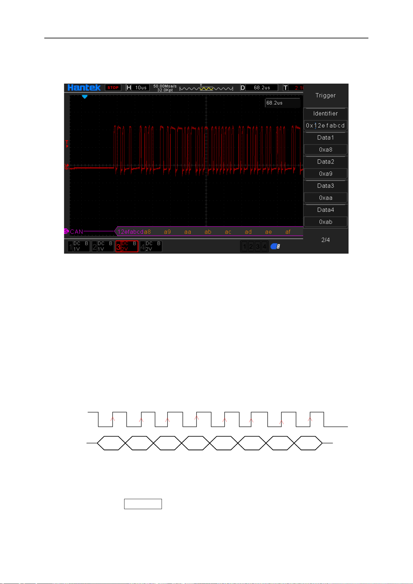
DPO6000, MPO6000 Series Digital Fluorescent Oscilloscope Product Manual V1.3
58
12efabcd; data 1: 0 × a8; data 2: 0 × a9; data 3: 0 × aa; data 4: 0 × ab; Idle level: low;
mode: normal. Adjust the trigger level. The trigger result is displayed as follows:
CAN decoding explanation:
1. The decoded data is displayed in hexadecimal;
2. "Frame ID" and "Check Digit" display color is purple, "Data" display color is orange;
3. When “?” Or “Please adjust the time base” appears, you need to adjust the time
base to get the decoding result.
SPI trigger [optional]
SPI is the abbreviation of Serial Peripheral Interface. It is a synchronous serial interface
technology introduced by Motorola. It is a high-speed, full-duplex, synchronous com-
munication bus.
D7 D6 D5 D4 D3 D2 D1 D0
CLK
DAT
In SPI triggering, when the timeout condition is met, the oscilloscope will trigger when it
finds the specified data. When using SPI triggering, you need to specify the SCL clock
source and SDA data source. The timing diagram of the SPI bus is as follows:
Press the front panel Trig Menu button to open the trigger function menu.
[Type] Select SPI and press V0 to confirm.

DPO6000, MPO6000 Series Digital Fluorescent Oscilloscope Product Manual V1.3
59
[Clock Source] Select CH1~CH4 or LA as the trigger source.
Note: LA must be inserted when LA is used as the trigger source.
[Slope] Select the required triggering edge (rising edge, falling edge, double edge) and
press V0 to confirm.
[Data source] Select CH1~CH4 or LA as the trigger source.
Note: LA must be inserted when LA is used as the trigger source.
[Overtime] The timeout period must be greater than the period of the CLK clock source.
[Data bit width] Set the data bit width.
[Data Bit] Set the number of data bits.
[Mode] Select the acquisition mode (auto, normal) and press V0 to confirm.
[Holdoff] Set the holdoff time.
[Decode] Switch the decoding function.
[Label position] The position where the decoded data is drawn on the screen (only
available when the decode function is turned on).
[Table] Data recording mode.
Trigger level knob: The analog channel can modify the trigger level value. Trigger the
mark and move up and down with the knob.
Digital channel: You can change the trigger threshold of the digital channel by setting
the threshold voltage.
Trigger settings:
Clock source: CH3; Slope: Rise; Data source: CH4; Overtime: 366ns; Data bit width: 8;
Data bit: 7 bits. Adjust the trigger level. The trigger result is displayed as follows:
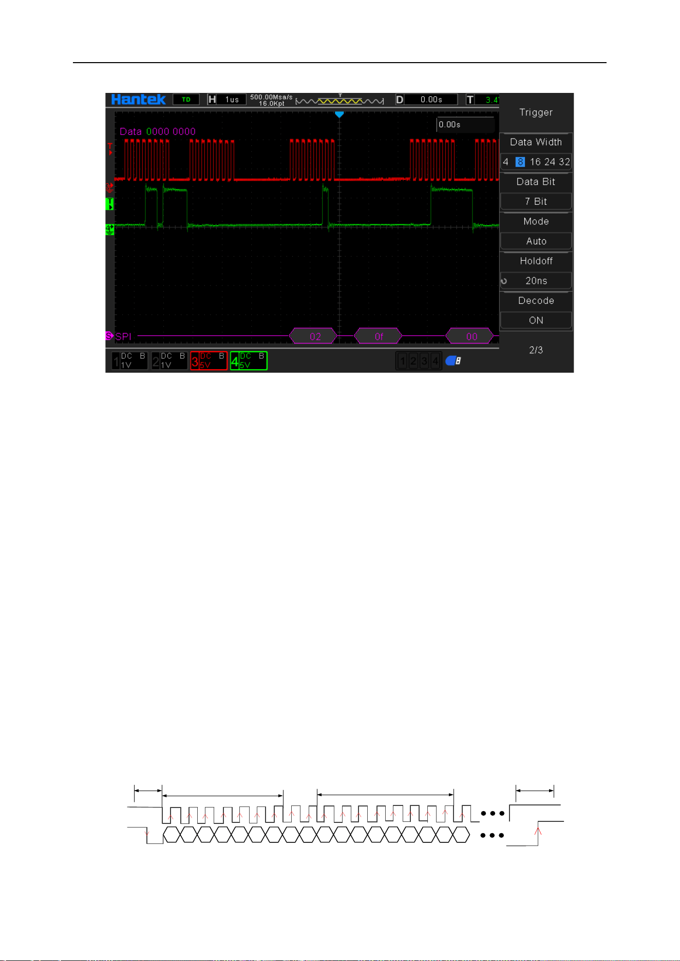
DPO6000, MPO6000 Series Digital Fluorescent Oscilloscope Product Manual V1.3
60
SPI decoding explanation:
1. The decoded data is displayed in hexadecimal;
2. The "Data" display color is purple;
3. When “?” Or “Please adjust the time base” appears, you need to adjust the time
base to get the decoding result.
IIC trigger [optional]
IIC (Inter-Integrated Circuit BUS) integrated circuit bus. This bus is designed by NXP
(formerly PHILIPS) company. It is mostly used for master-slave communication be-
tween master controller and slave devices. It is used in small data volume occasions,
short transmission distance, any time there can only be one host, etc.
IIC address addressing mode is divided into 7-bit addressing mode and 10-bit address-
ing mode
7-bit addressing
In the 7-bit addressing process, the slave address starts to be transmitted in the first
byte after the start signal. The first 7 bits of the byte are the slave address, and the 8th
bit is the read and write bit, where 0 means write and 1 Means read.
A6
SCL
SDA
1
2
3
4
5
6
7
8
A5 A4 A3 A2 A1
A0
R
W
ACK
9
D7
1
2
3
4
5
6
7
8
D6 D5 D4 D3 D2
D1 D0
ACK
9
IIC address
IIC data
Start condition
Stop condition

DPO6000, MPO6000 Series Digital Fluorescent Oscilloscope Product Manual V1.3
61
10-bit addressing
The 10-bit addressing and 7-bit addressing of the IIC bus are compatible, so that de-
vices with 7-bit address and 10-bit address mode can be used on the same bus at the
same time. When transmitting 10-bit addresses, the first byte is a special reserved ad-
dress. To indicate that the 10-bit address is currently being transmitted.
1
SCL
SDA
1
2
3
4
5
6
7
8
1 1 1 0
A
9
A
8
R
W
AC
K
9
D
7
1
2
3
4
5
6
7
8
D
6
D
5
D
4
D
3
D
2
D
1
D
0
AC
K
9
IIC address
IIC data
A
7
1
2
3
4
5
6
7
8
A
6
A
5
A
4
A
3
A
2
A
1
A
0
AC
K
9
Start condition
Stop condition
The IIC (Inter-Integrated Circuit Bus) signal settings include a serial data (SDA) line and
a serial clock (SCL) line connected to an oscilloscope, and then specify the input signal
threshold voltage level.
Press the front panel Trig Menu button to open the trigger function menu.
[Type] Select IIC and press V0 to confirm.
[Address width] Select 7 or 10 digits.
[Clock Source] Select CH1~CH4 or LA as the trigger source.
Note: LA must be inserted when LA is used as trigger source
[Data source] Select CH1~CH4 or LA as the trigger source.
Note: LA must be inserted when LA is used as trigger source
[When] Set IIC trigger conditions:
Start bit: IIC start condition detected
Stop bit: IIC stop condition detected
No response: trigger when IIC bus response level error
Address: IIC address is received, trigger when the data is equal to the user set value
Restart: triggered when a new start condition occurs before the stop condition
Address and data: Triggered when the IIC address is received and the data (4 bytes of
data) is equal to the user set value.
[Address] Identifier data when IIC is triggered.
[Data 1] Data when IIC is triggered
[Data 2] Data when IIC is triggered
[Data 3] Data when IIC is triggered
[Data 4] Data when IIC is triggered
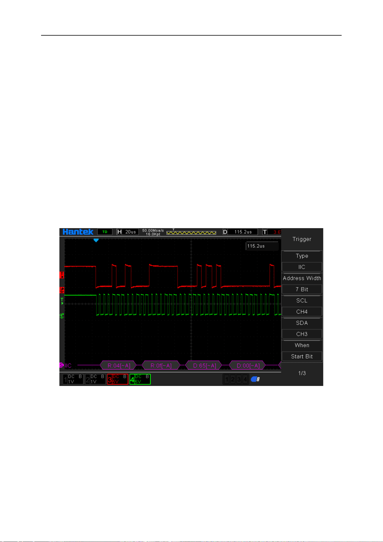
DPO6000, MPO6000 Series Digital Fluorescent Oscilloscope Product Manual V1.3
62
[Mode] Select the acquisition mode (auto, normal) and press V0 to confirm.
[Holdoff] Set the holdoff time.
[Decode] Switch decoding function
[Label position] The position where the decoded data is drawn on the screen (only
available when the decode function is turned on).
[Table] Data recording mode
Trigger level knob: The analog channel can modify the trigger level value. Trigger the
mark and move up and down with the knob.
Digital channel: You can change the trigger threshold of the digital channel by setting
the threshold voltage.
Trigger settings:
Address width: 7 bits; clock source: CH4; data source: CH3; When: start bit. Adjust the
trigger level. The trigger result is displayed as follows:
IIC decoding explanation:
1. The decoded data is displayed in hexadecimal;
2. "Address" and "Data" are displayed in purple; "W" indicates a write operation, "R"
indicates a read operation, "D" indicates decoded data, and "~ A" indicates no
acknowledge bit;
3. When “?” Or “Please adjust the time base” appears, you need to adjust the time
base to get the decoding result.

DPO6000, MPO6000 Series Digital Fluorescent Oscilloscope Product Manual V1.3
63
Protocol decoding
Users can easily find errors, debug hardware, and accelerate development progress
through protocol analysis. DPO6000 / MPO6000 series machines provide decoding of
5 common protocols, including UART, LIN, CAN, IIC and SPI.
Note: Only when the user correctly configures the protocol trigger setting parameters
can the correct decoding result be obtained.
Decoding mode
The decoding function is only available when the protocol is triggered. Turn on the de-
coding switch. At this time, the magenta serial decoding cursor appears on the left side
of the oscilloscope (the default is at the bottom of the screen). The user can change the
position of the label by selecting the label position menu The decoded position acquisi-
tion waveform has a better display position for users to analyze the decoded data.
Table mode
The table function can only be used when the protocol is triggered. When the table
mode is enabled, the oscilloscope does not perform waveform data acquisition and
display when the oscilloscope is running in the table mode. It only displays the correct
protocol decoded data. The decoded data is transmitted to the screen in real time.
When the oscilloscope is running in table mode, only F1, F2, F3, RUN / Stop soft keys
can be used, and other keys cannot be used. If the user needs to set other parameters
of the serial port, he needs to exit table mode. After the user pauses, the decoded data
can be exported for analysis.
Mathematics
Addition
The waveform values of data source 1 and data source 2 are added point by point and
the result is displayed.
Steps:
1. Press the Math button on the front panel to enter the MATH function menu. Turn the
multi-function knob V0 to select "+" for addition operation.
2. Press the [Data Source 1] and [Data Source 2] soft keys and turn the multi-function
knob V0 to select the data source. 4 analog channels can be used as data sources.
The resulting math waveform is displayed on the screen and labeled "M".
3. Operation waveform settings:

DPO6000, MPO6000 Series Digital Fluorescent Oscilloscope Product Manual V1.3
64
[Offset]: Set the vertical offset of the operation waveform relative to the time axis;
[Scale]: Set the unit volt value in the vertical direction.
The setting of the operation waveform in the horizontal direction is the same as that of
the data source waveform.
[Setting] is not available at this time.
Subtraction
Subtract the waveform values of data source 1 and data point by point and display the
result.
The operation steps are the same as those of [Addition].
Multiplication
Multiply the waveforms of data source 1 and data source 2 point by point and display
the result.
The operation steps are the same as those of [Addition].
The units of the calculation waveform "offset" and "scale" are user-defined (represented
by U).
Division
Divide the waveform of data source 1 and data source point by point and display the
result. It can be used to analyze the multiple relationships between the waveforms of
two channels.
The operation steps are the same as those of [Addition].
Note: When the voltage value of data source 2 is zero, the operation result is treated as
invalid.
The units of the calculation waveform "offset" and "scale" are user-defined (represented
by U).
FFT
FFT uses the analog input channel waveform to calculate a fast Fourier transform. The
FFT operation can be used to convert a time domain (YT) signal into its frequency
components (spectrum), showing the relationship between dB V and frequency. The
horizontal axis reads from time to frequency (Hz) and the vertical reads from V to dB.
FFT operations can be used for the following tasks:
◆ Measure harmonic content and distortion in the system

DPO6000, MPO6000 Series Digital Fluorescent Oscilloscope Product Manual V1.3
65
◆ Represents noise characteristics in DC power supply
◆ Analysis of vibration
Steps:
1. Press the Math button on the front panel to open the Math function menu. Turn the
multi-function knob V0 to select “FFT” for fast Fourier transform operation.
2. Press the [Data Source] soft key and turn the multi-function knob V0 to select a data
source. 4 analog channels can be used as data sources. The resulting math waveform
is displayed on the screen and labeled "M".
3. Operation waveform settings:
[Center]: Set the frequency of the frequency domain waveform corresponding to the
horizontal center of the screen.
[Span]: Set the horizontal scale of the FFT waveform.
[Reference level]: Set the reference level of the FFT waveform.
[Scale]: Set the unit volt value in the vertical direction.
[Vertical Unit]: Select the unit of the vertical axis. The units of the vertical axis can use
the logarithmic scale to display the vertical amplitude in dB or the linear scale to display
the vertical amplitude in Vrms.
[Window]: Select the appropriate window.
When window functions are used, spectral leakage can be greatly reduced. This series
of oscilloscopes provide FFT window functions with 6 different characteristics, which
are suitable for measuring different waveforms. Users can select window functions
based on different waveforms and their characteristics.
Window
Measurement
Characteristics
Rectangular
Transient or short pulse wave-
form
Dedicated window for discrete window
similar to the situation when no window
is multiplied
Hanning
Period waveform
Better frequency resolution
Poorer amplitude resolution
Hamming
Transient or short pulse wave-
form
A little bit better frequency resolution
than Hanning.
Blackman
Single frequency signal, search
for higher order harmonics
The best amplitude resolution;
the poorest frequency resolution
Bartlett
(Triangle)
Stronger narrow band signal
Better frequency resolution
Flattop
Period waveform
Better amplitude resolution
Poorer frequency resolution
[Show-Only]: Set whether to display only the FFT calculation result and not the data

DPO6000, MPO6000 Series Digital Fluorescent Oscilloscope Product Manual V1.3
66
source waveform.
[Auto Scale]: The system can automatically set to the best display state of the FFT
waveform.
Note:
1. Signals with DC components or deviations can cause errors or deviations in the FFT
waveform components. In order to reduce the DC component, the channel coupling of
the data source can be set to "AC" mode.
2. To reduce the random noise and aliasing frequency components of repetitive or sin-
gle pulse events, set the [Acquisition Mode] of the oscilloscope to "Average".
Measure FFT waveform with cursor
To perform cursor measurement, first press Cursors on the front panel of the oscillo-
scope to turn on cursor measurement. Press the [Mode] soft key to select manual or
tracking. Use AX and BX cursors to measure the frequency and the difference between
the two frequencies (BX-AX). Use AY and BY cursors to measure amplitude and ampli-
tude difference (BY-AY).
Integral
Calculate the points for the specified data source. For example, you can use integrals
to calculate the energy of a pulse or measure the area under a waveform.
The operation steps are the same as those of the [Addition] operation, and the integral
operation is performed on a single data source.
The units of the calculation waveform "offset" and "scale" are user-defined (represented
by U).
Differential
Calculates the discrete-time derivative of the specified data source. For example, a dif-
ferential can be used to calculate the instantaneous slope of a waveform.
The operation steps are the same as those of the [Addition] operation, and a differential
operation is performed on a single data source.
[Setting]: Set the single-step value of differential operation waveform display.
The units of the calculation waveform "offset" and "scale" are user-defined (represented
by U).
Square root
Calculates the square root of the specified data source waveform point by point and
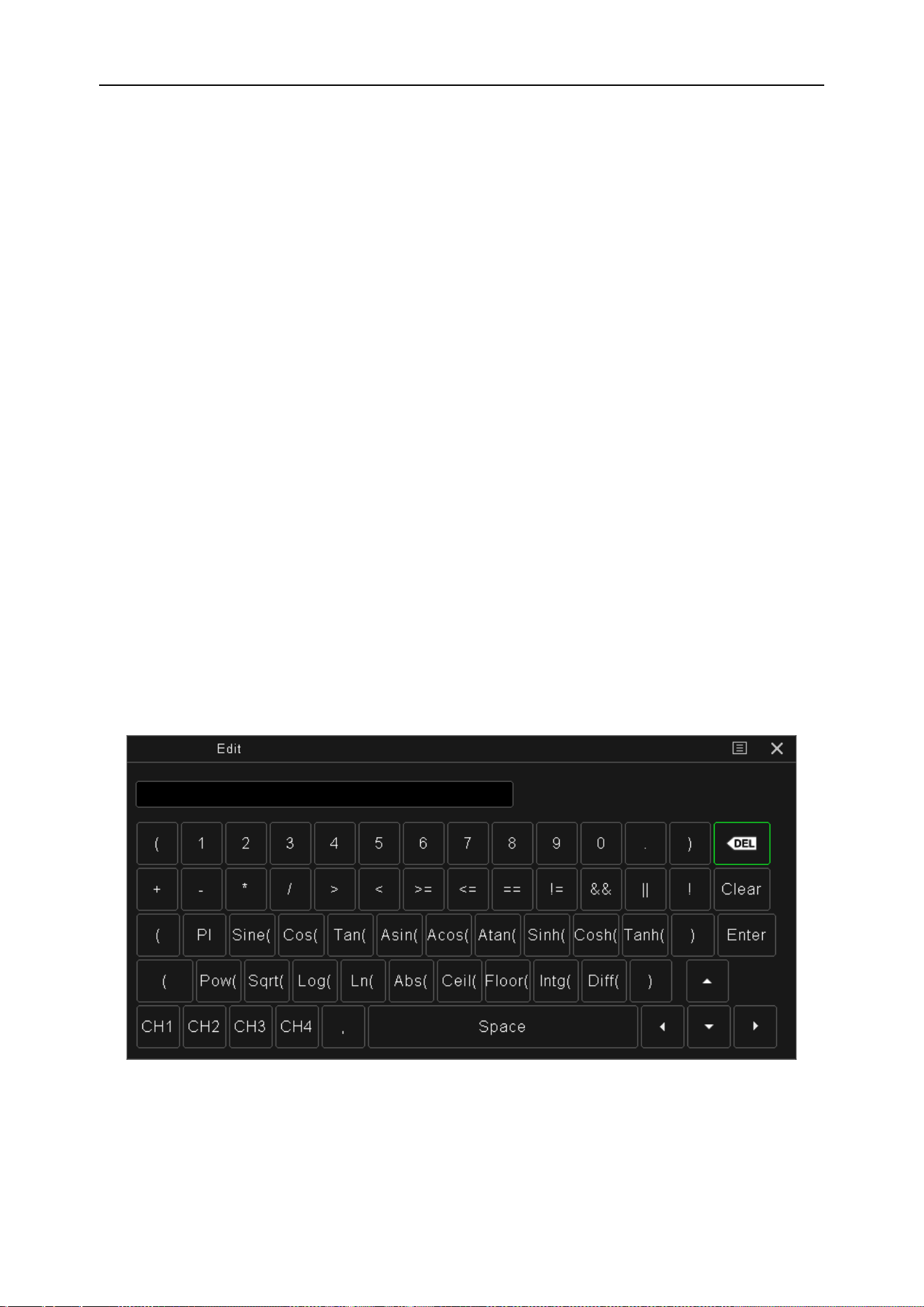
DPO6000, MPO6000 Series Digital Fluorescent Oscilloscope Product Manual V1.3
67
displays the result.
The operation steps are the same as those of the [Addition] operation. The square root
operation is performed on a single data source.
The units of the calculation waveform "offset" and "scale" are user-defined (represented
by U).
Expression
User-defined operation expressions of any one or more analog channel waveforms of
CH1-CH4.
Math waveform settings:
[Offset]: Set the vertical offset of the operation waveform relative to the time axis;
[Scale]: Set the unit volt value in the vertical direction.
The setting of the operation waveform in the horizontal direction is the same as that of
the data source waveform.
[Setting]: Edit the operation expression and set the data source waveform single step
value and threshold.
The units of the calculation waveform "offset" and "scale" are user-defined (represented
by U).
The expressions available for "editing" are shown below.
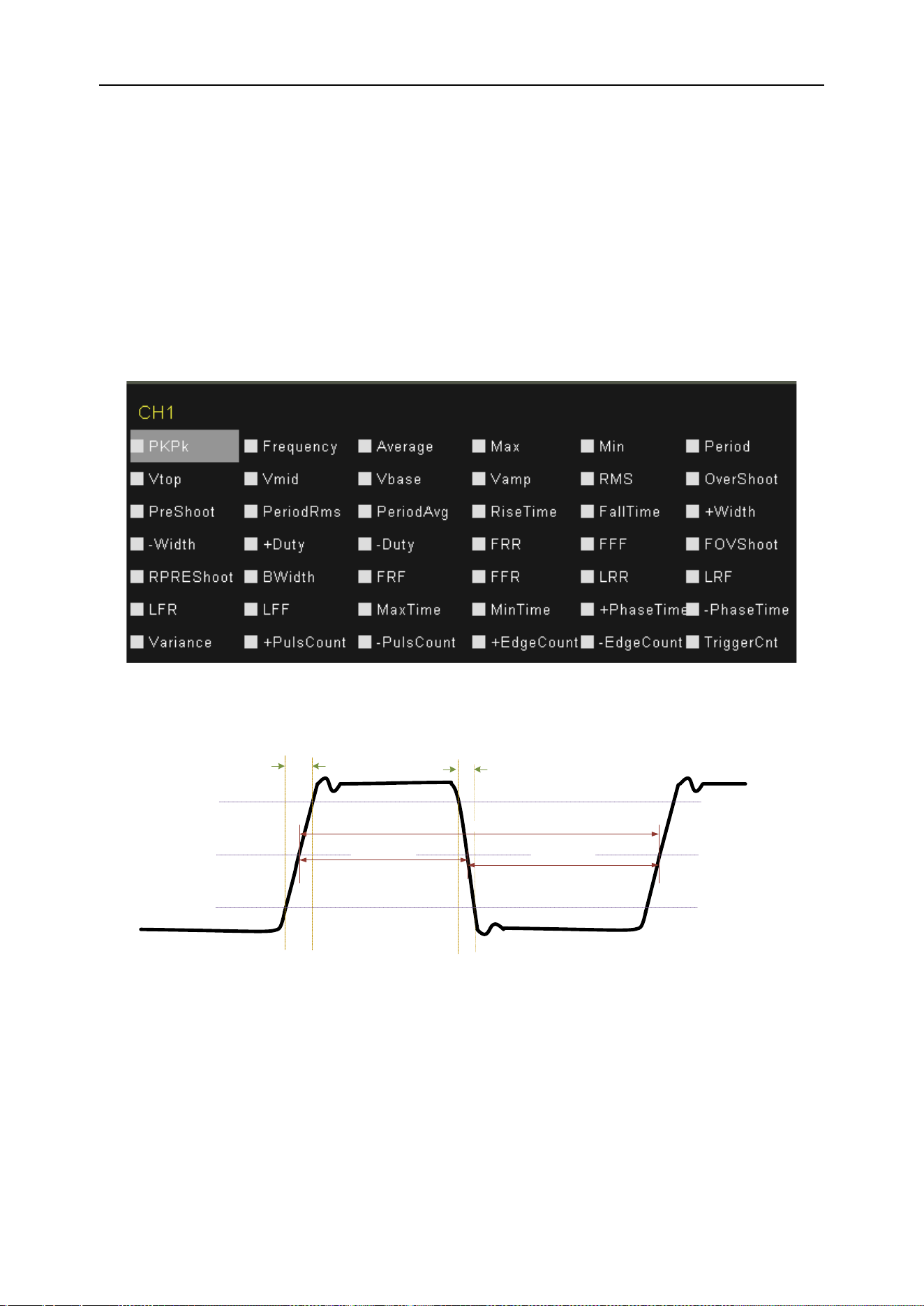
DPO6000, MPO6000 Series Digital Fluorescent Oscilloscope Product Manual V1.3
68
Measurement
Measurement parameter description
DPO6000 / MPO6000 series oscilloscopes provide automatic measurement of 42 kinds
of waveform parameters, and statistics and analysis functions of measurement results.
In addition, users can also use the digital multimeter [DVM] to achieve more accurate
frequency measurement. Before performing the measurement operation, please under-
stand these 42 waveform parameters in detail.
Time parameter
Rise time
Threshold upper limit
Fall time
Threshold Mid-Value
Threshold lower limit
Positive width
Negative width
Period
1. Period [P
k
-P
k
]: Defined as the time between the middle threshold crossing points of
two consecutive, same-polarity edges.
2. Frequency: Defined as the reciprocal of the period.
3. Rise Time: The time it takes for the signal amplitude to rise from the lower threshold
to the upper threshold.
4. Fall Time: The time it takes for the signal amplitude to fall from the upper threshold
value to the lower threshold value.
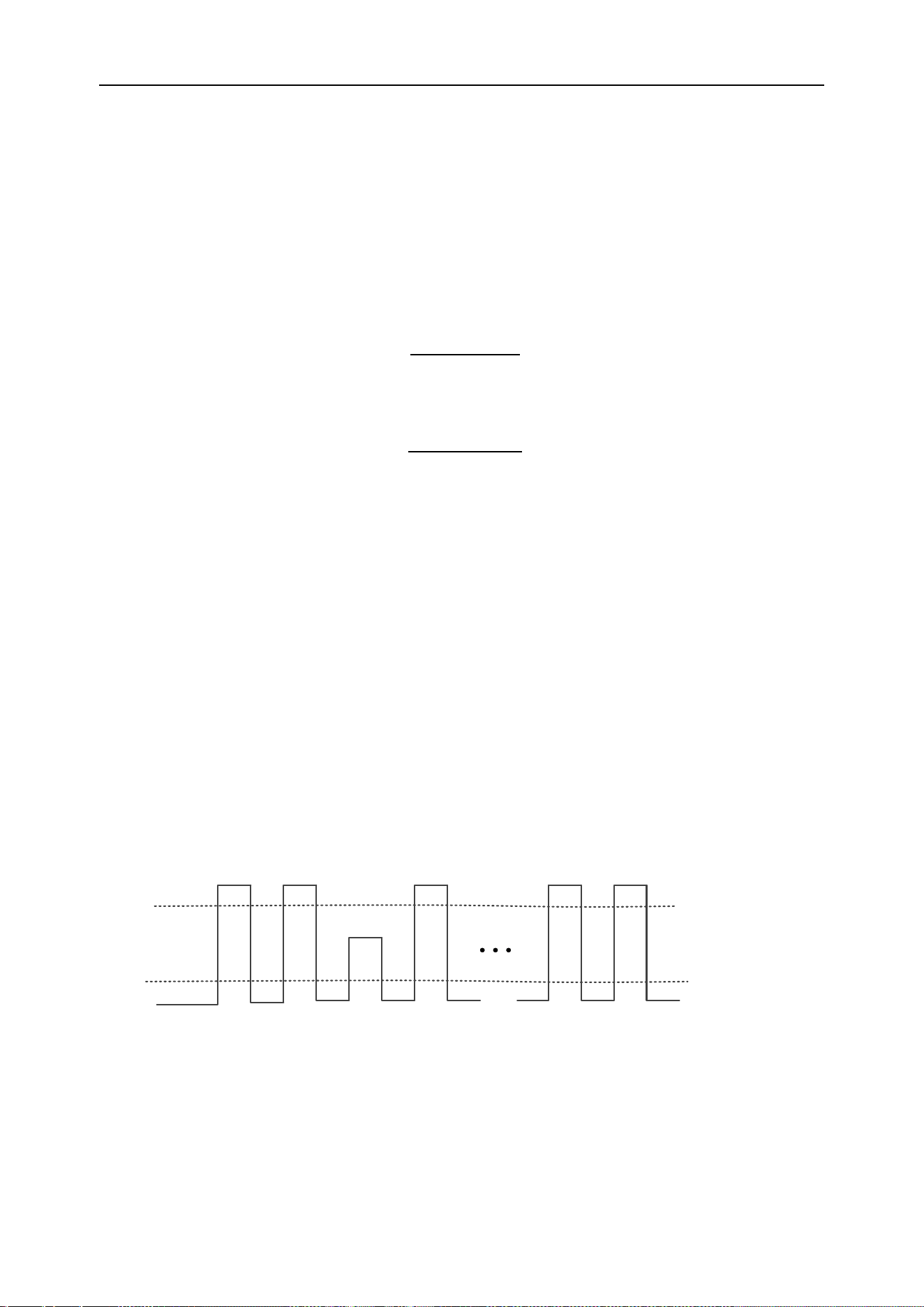
DPO6000, MPO6000 Series Digital Fluorescent Oscilloscope Product Manual V1.3
69
5. Positive pulse width [+ Width]: The time difference from the middle value of the
threshold of the rising edge of the pulse to the middle value of the threshold of the next
falling edge.
6. Negative pulse width [-Width]: The time difference from the threshold intermediate
value of the falling edge of the pulse to the threshold intermediate value of the next ris-
ing edge.
7. Positive Duty Cycle [+ Duty]: The ratio of positive pulse width to period.
8. Negative Duty Cycle [-Duty]: The ratio of negative pulse width to period.
9. Burst Length [B-Width]: The time from the first edge of the data source to the last
edge of the data source.
10. Maximum time [V
max
Time]: The time value corresponding to the maximum value
(V
max
) of the waveform.
11. Minimum time [V
min
Time]: The time value corresponding to the minimum value (V
min
)
of the waveform.
Note: The upper threshold, middle threshold, and lower threshold are 90%, 50%, and
10%, respectively.
Count value parameters
1. Positive Pulse Count [+ Pulse Count]: The number of positive pulses rising from be-
low the lower threshold to above the upper threshold.
Threshold upper limit
Threshold lower limit
1
2
3
n
n-1
2. Negative pulse number [- Pulse Count]: the number of negative pulses from above
the upper threshold to below the lower threshold.
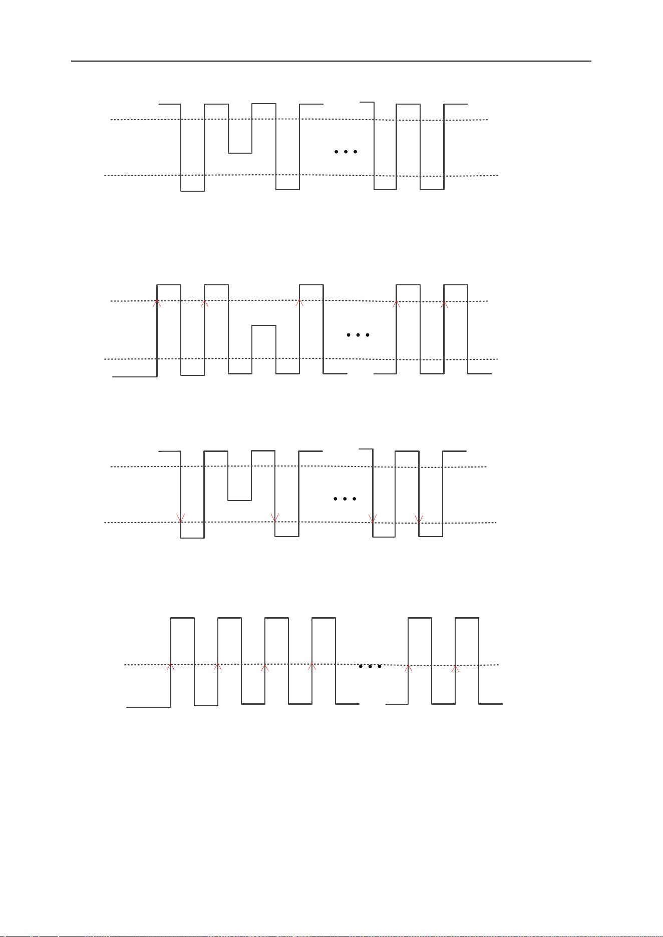
DPO6000, MPO6000 Series Digital Fluorescent Oscilloscope Product Manual V1.3
70
Threshold upper limit
1 2
n-1 n
Threshold lower limit
3. Rise Pulse Count: The number of rising edges rising from below the lower threshold
to above the upper threshold.
Threshold upper limit
Threshold upper limit
1
2
3
n
n-1
4. Fall Pulse Count: The number of falling edges from the upper threshold to the lower
threshold.
Threshold upper limit
Threshold lower limit
1 2
n-1 n
5. Trigger Count: The number of rising (or falling) edges from the threshold.
Threshold value
1
2 3 4 n-1 n
Note: The above measurement items are only applicable to analog channels. The de-
fault values for the upper and lower thresholds are 90% and 10%, respectively.
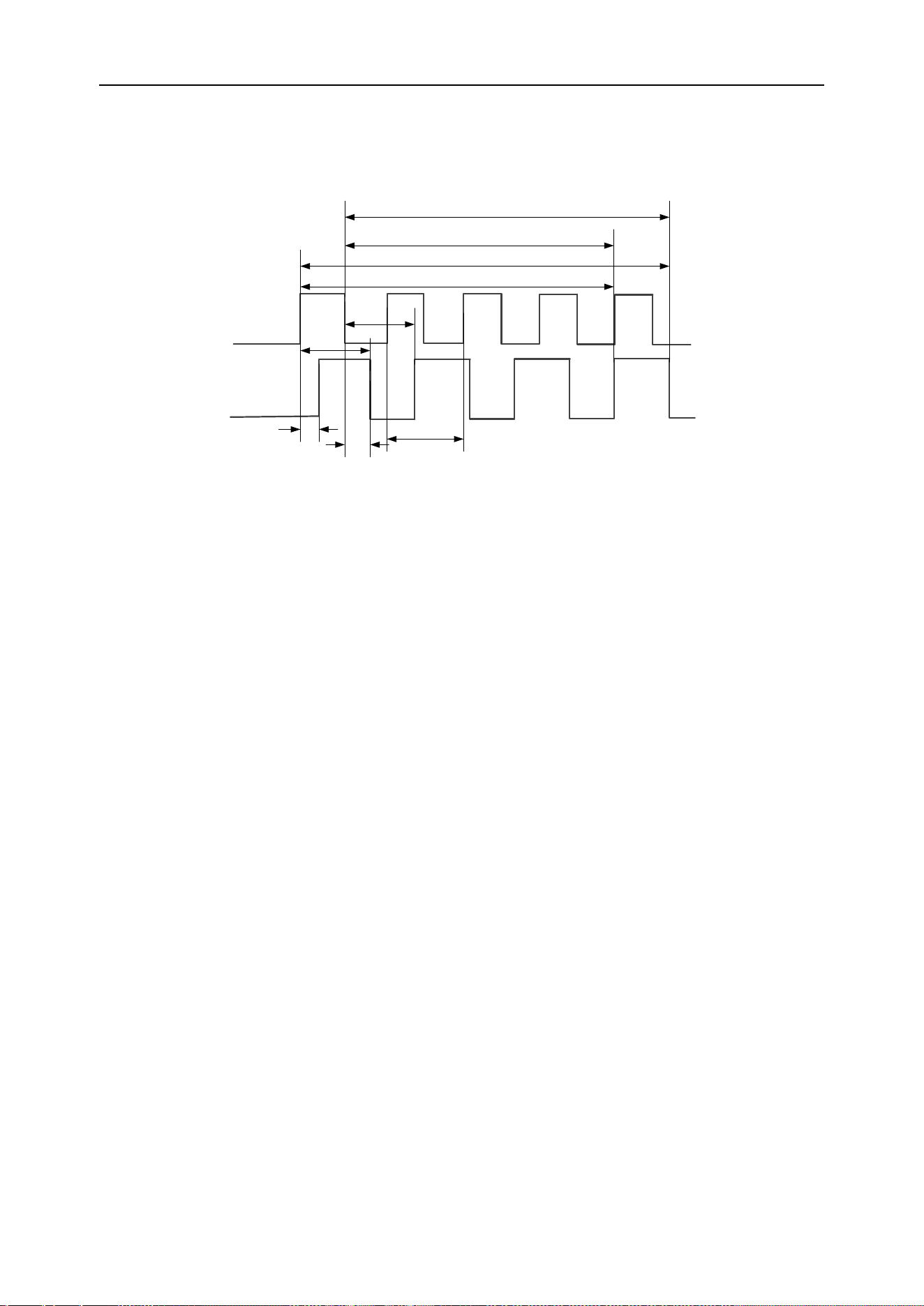
DPO6000, MPO6000 Series Digital Fluorescent Oscilloscope Product Manual V1.3
71
Delay and phase parameters
Signal
source A
Signal
source B
Period
FRR
FFF
FRF
FFR
LRR
LRF
LFR
LFF
Data source A and data source B, that is, data source A and data source B in the
measurement setting menu, can be any channel from CH1-CH4 or D0-D15, please re-
fer to the description in "Measurement Settings" for setting.
1. FRR [First Delay Rise-Rise]: ↑ A-> ↑ B, the time difference between the first rising
edge of data source A and data source B.
2. FFF [First Delay Fall-Fall]: ↓ A-> ↓ B, the time difference between the first falling
edge of data source A and data source B.
3. FRF [First Delay Rise Fall]: ↑ A-> ↓ B, the time difference between the first rising
edge of data source A and the first falling edge of data source B.
4. FFR [First Delay Fall Rise]: ↓ A-> ↑ B, the time difference between the first falling
edge of data source A and the first rising and falling edge of data source B.
5. LRR: [Last Delay Rise-Rise]: ↑ A-> ↑ B, the time between the first rising edge of data
source A and the last rising edge of data source B.
6. LRF [Last Delay Rise Fall]: ↑ A-> ↓ B, the time between the first rising edge of data
source A and the last falling edge of data source B.
7. LFR [Last Delay Fall Rise]: ↓ A-> ↑ B, the time between the first falling edge of data
source A and the last rising edge of data source B.
8. LFF [Last Delay Fall-Fall]: ↓ A-> ↓ B, the time between the first falling edge of data
source A and the last falling edge of data source B.
9. Phase [Phase Rise Time]: ↑ A-> B, the phase difference calculated according to "De-
lay 1-> 2" and the period of data source 1, expressed in degrees.
10. Phase [Phase Fall Time]: ↓ A-> B, the phase difference calculated according to “De-
lay 1-> 2” and the period of data source 1, expressed in degrees.
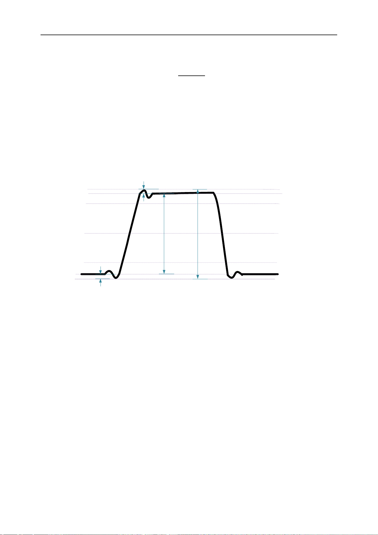
DPO6000, MPO6000 Series Digital Fluorescent Oscilloscope Product Manual V1.3
72
The calculation formula of the phase is:
Among them,
Phase means "phase ↑ A-> B" or "phase ↓ A-> B"
Delay means "Delay FRR" or "Delay FFF"
Period1 represents the period of digital data source source 1.
Voltage parameters
Threshold upper limit
Threshold Mid- limit
Threshold lower limit
Overshoot
Amplitude
Vmax
Vtop
Vbase
Vmin
Pk-Pk
Preshoot
1. Maximum [V
max
]: The voltage value from the highest point of the waveform to GND.
2. Minimum [V
min
]: The voltage value from the lowest point of the waveform to GND.
3. Double peak [P
k
-P
k
]: The voltage value from the highest point to the lowest point of
the waveform.
Double peak = Maximum-Minimum
4. Top value [V
top
]: The voltage value from the flat top of the waveform to GND.
5. Bottom value [V
base
]: The voltage value from the flat bottom of the waveform to GND.
6. Amplitude [V
ampl
]: The voltage value from the top to the bottom of the waveform.
Amplitude = Top value-Low value
7. Middle value [V
mid
]: The actual voltage value corresponding to the middle value of
the measurement threshold.
8. Average: Arithmetic average over the entire waveform or gated area.
9. Period average: The arithmetic average of the first period of the waveform.

DPO6000, MPO6000 Series Digital Fluorescent Oscilloscope Product Manual V1.3
73
Among them, xi is the measurement result of the i-th point, and n is the number of
measured points.
10. Root Mean Square [Vrms]: The root mean square value over the entire waveform or
gated area.
11. Root-Mean-Square [Per-Vrms]: Root mean square value in one cycle.
Among them, xi is the measurement result of the i-th point, and n is the number of
measured points.
12. Overshoot: The ratio of the difference between the maximum value of the waveform
and the top value to the amplitude.
13. Pre-shoot: The ratio of the difference between the minimum value and the bottom
value of the waveform to the amplitude.
14. Fall Overshoot: The ratio of the difference between the maximum value and the top
value of the waveform to the amplitude.
15. Rise Pre-shoot: The ratio of the difference between the minimum value of the wave-
form and the bottom value to the amplitude.
16. Variance: The average of the sum of the squares of the difference between the am-
plitude value of each waveform point and the average value of the waveform over the
entire waveform or gated area. The variance reflects the degree of fluctuation of the
waveform. Calculated as follows:
Among them, V
ampi
is the amplitude value of the i-th point, Average is the average value
of the waveform, and n is the number of measured points.
All measurements
Press Meas on the front panel to enter the measurement setting interface. Press [All
Measurements] to measure 42 waveform parameters with one key. The measurement
results are displayed at the bottom of the screen, and the color markers consistent with
the current measurement channel are displayed.
Note: If the measurement display is "
*****
", it means that the current measurement
source has no signal input, or the measurement result is not within the valid range (too
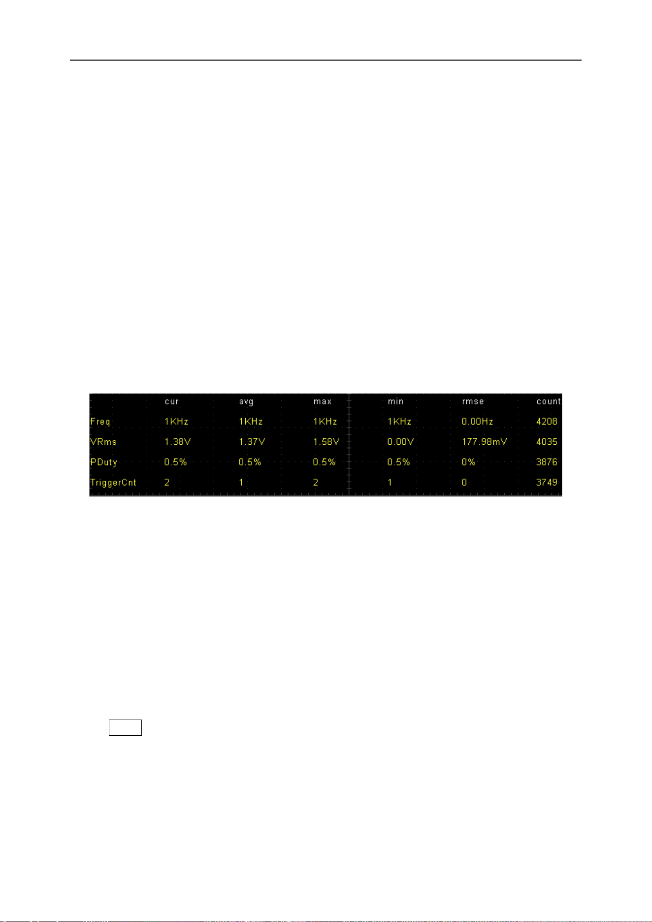
DPO6000, MPO6000 Series Digital Fluorescent Oscilloscope Product Manual V1.3
74
large or too small).
[Setting]: Set the data source A and data source B to perform the measurement of
"Delay and Phase Parameters".
[Gating]: User-defined measurement range, indicated by cursor A and cursor B.
Measurement statistics
Statistic and display the current value, average value, maximum value, minimum value,
root mean square error and count value of the waveform parameters of the selected
data source.
Press [Type] and turn the multi-function knob V0 to select the waveform parameters to
perform measurement statistics.
Waveform parameters of measurement statistics can be displayed 4 kinds at a time,
and more than 4 kinds of waveform parameters will be covered and updated from bot-
tom to top.
[Clear all]: Clear all measurement data on the current display, including measurement
results, statistical results, and gate control.
Digital Voltmeter (DVM)
DPOO6000 / MPO6000 series oscilloscopes have built-in digital voltmeter (DVM) and
frequency meter, which can measure the voltage and frequency of analog channels,
and monitor the signal when the oscilloscope is running or stopped, which can improve
the user's counting and frequency measurement experience.
DVM performs 5-digit AC RMS, DC, AC + DC RMS voltage measurements and 6-digit
frequency measurements.
Press Meas-> Digital Voltmeter-> Enable on the front panel to turn on the digital volt-
meter;
[Data source] Select the data source to be tested.
[Type] Select the type of digital voltmeter display.
When DVM measurement is turned on, the display is as shown below. The DVM dis-
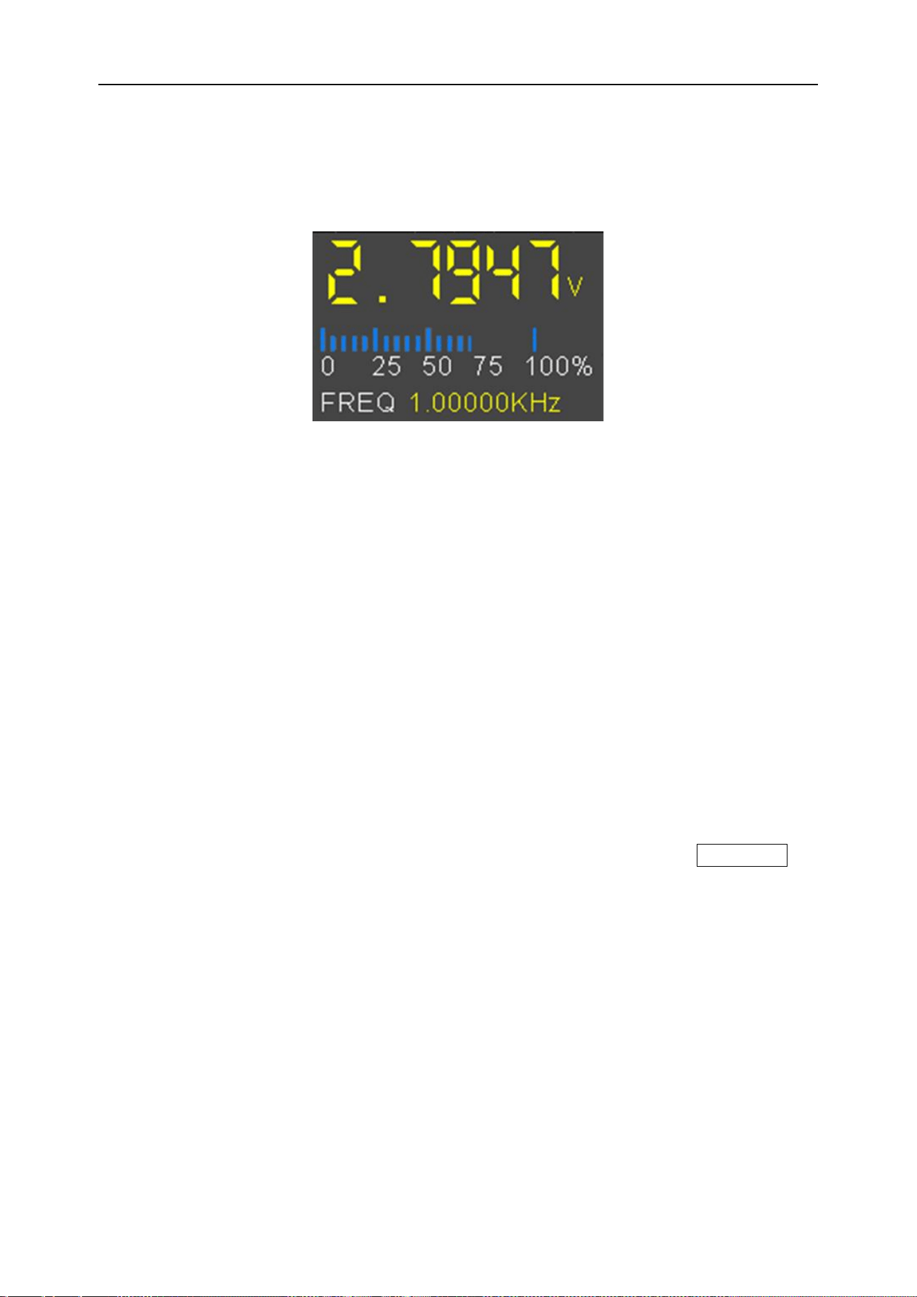
DPO6000, MPO6000 Series Digital Fluorescent Oscilloscope Product Manual V1.3
75
play results include the range. The range of the range is determined by the vertical
scale and vertical offset of the channel. The range is the screen range. The upper spe-
cific value is the measurement result, the middle is the range, and the lower is the fre-
quency of the measurement.
Grid scale measurement
Grid scale measurement: This method can be used to quickly and intuitively estimate
the frequency and voltage amplitude of the waveform. It can be easily measured by the
division of the grid and the scale factor.
For example, a simple measurement can be made by calculating the relevant major
and minor scale divisions and multiplying by the scale factor. If it is calculated that there
are 6 major vertical scale divisions between the maximum and minimum values of the
waveform, and the known scaling factor is 50mV/division, the peak-to-peak voltage can
be calculated as follows:
6 divisions × 50mV/division = 300mV
Automatic measurement
Quick measurement after AUTO
After connecting the oscilloscope correctly, input a valid signal, press the Auto Scale
key to automatically set the waveform and open the following function menu:
Single cycle: Set the screen to display the signal of a single cycle automatically. At the
same time, a single cycle of "time parameter" and "voltage parameter" measurement is
performed on the current data source, and the measurement result is displayed at the
bottom of the screen.
Multi-cycle: Set the screen to automatically display signals for multiple cycles. At the
same time, multi-cycle “time parameter” and “voltage parameter” measurements are
performed on the current data source, and the measurement results are displayed at
the bottom of the screen.
Auto range: Select the scale automatically set by the system: "horizontal and vertical
scale", "horizontal scale" or "vertical scale".

DPO6000, MPO6000 Series Digital Fluorescent Oscilloscope Product Manual V1.3
76
Data source: Set the channel to be set automatically: "Display only", "All". Display only:
After the system performs the automatic setting, only the waveform of the opened
channel with signal input is displayed; all: After the system performs the automatic set-
ting, the waveforms of all channels with signal input are displayed.
Cursor measurement
Cursor measurement is performed by moving the cursor. The cursors always appear in
pairs, and the displayed reading is the measured value. There are two types of cursors:
amplitude and time cursors.
Amplitude cursor: The amplitude cursor is displayed as a horizontal dashed line and
is used to measure parameters in the vertical direction.
Time cursor: The time cursor is displayed as a vertical dashed line and is used to
measure parameters in the horizontal direction.
There are two methods for cursor measurement: manual and tracking.
1. Manual
The horizontal cursor or vertical cursor appears in pairs to measure time and voltage.
The cursor position can be adjusted manually. When using the cursor, be sure to set
the Data Source to the waveform you want to measure on the display.
2. Tracking
The horizontal cursor intersects with the vertical cursor to form a cross cursor. The
cross cursor is automatically positioned on the waveform. The horizontal position of the
cross cursor on the waveform can be adjusted by selecting "Source A" or "Source B"
and turning the V0 knob. The coordinates of the cursor cross point will be displayed on
the oscilloscope screen.
Press the Cursors button to enter the cursor menu.
Option
Setting
Comments
Mode
Manual
Tracking
Select a measurement cursor and display it.
Data
source
CH1~CH4
MATH
Selects a data source for cursor measurement.
Select
cursor
AX(BX)
AXBX
AY(BY)
AYBY
The highlighted cursor selected by AYBY can be
moved freely. You can select two cursors and move
them simultaneously. The box behind the cursor
shows the position of the cursor.
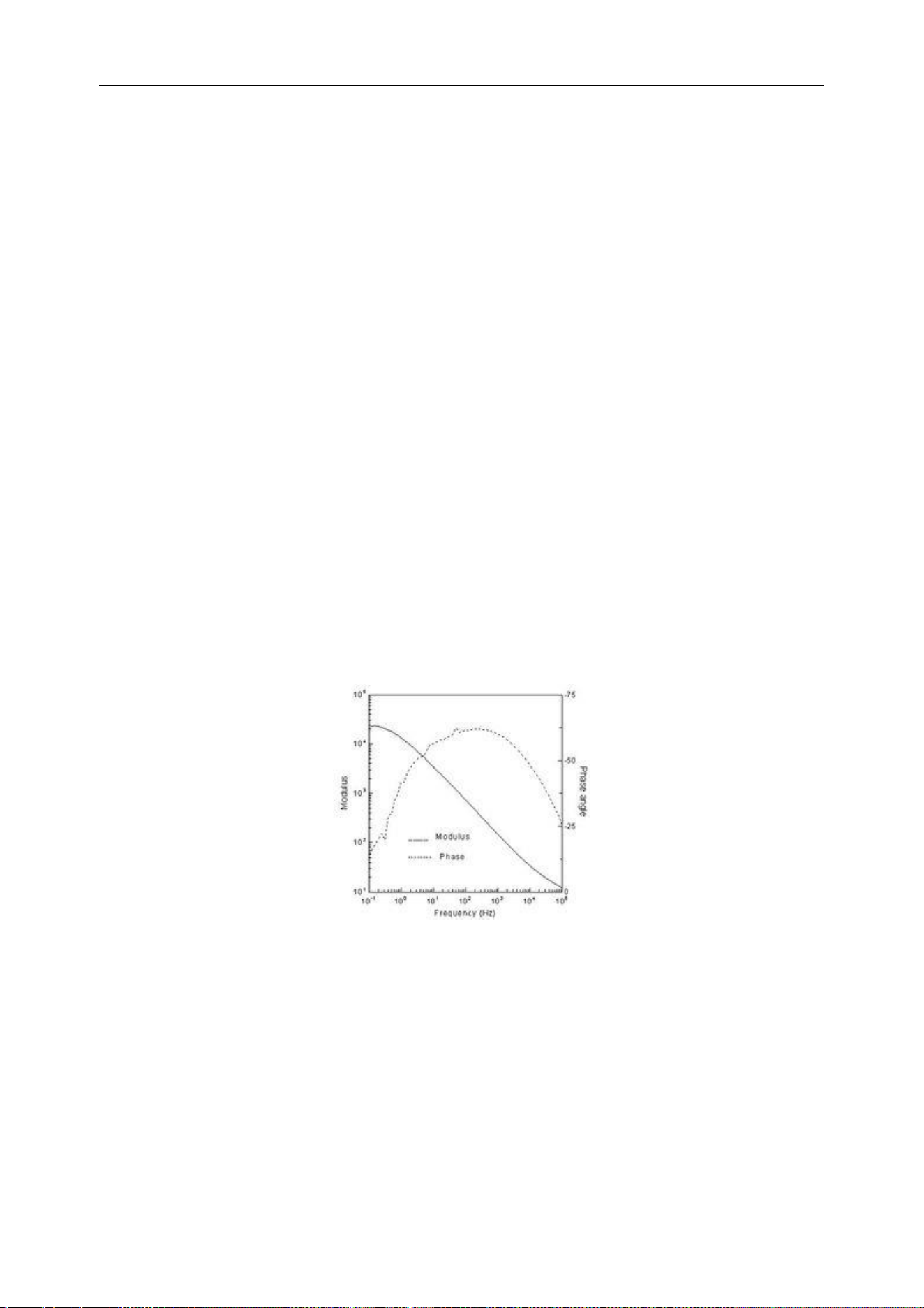
DPO6000, MPO6000 Series Digital Fluorescent Oscilloscope Product Manual V1.3
77
Move Cursor: Select the cursor type and turn the multi-function knob V0 to move the
cursor. The cursor can only be moved when the cursor menu is open.
Bode plots (signal source series)
The Bode plots are a semi-logarithmic plot of the transfer function versus frequency of
a linear non-time-varying system. The horizontal axis is frequency and the vertical axis
is expressed on a log scale. The frequency response of the system can be seen using
the Bode plot. The Bode plots are generally composed of two diagrams. One ampli-
tude-frequency diagram represents the change in the decibel value of the frequency
response gain versus frequency, and the other phase-frequency diagram represents
the change in phase versus frequency of the frequency response.
The figure of the Bode plots is related to the system's gain, the number of poles and
zeroes, and the position. As long as the relevant information is known, an approximate
Bode plot can be drawn with simple calculations. This is the advantage of using a Bode
plots.
Bode plots brief
The Bode plots is also called the amplitude frequency response and phase frequency
response curve, which is generally the rectangular coordinate of the amplitude and
phase at the fundamental frequency of the rotating machine relative to the rotor speed.
Bode plots
The logarithmic frequency characteristics are drawn using the method of polyline ap-
proximation when drawing. General drawing of Bode plots:
When drawing a Bode plots, it is performed in three frequency bands. The amplitude-
frequency characteristics are drawn first, in the order of mid-band, low-band, and high-
band. The frequency characteristics (or frequency response) of the three frequency
bands together are the amplitude-frequency characteristics of the entire frequency
band, and then the corresponding phase-frequency characteristics are drawn according
to the amplitude-frequency characteristics.

DPO6000, MPO6000 Series Digital Fluorescent Oscilloscope Product Manual V1.3
78
Application of Bode plots
When studying the frequency response of the amplifier circuit, because the frequency
range of the signal is very wide (from a few hertz to several hundred megahertz or
more), the amplification factor of the amplifier circuit is also very large (up to one million
times). It is a compressed coordinate to expand the field of view when drawing the fre-
quency characteristic curve, the frequency coordinates are exponentially scaled, and
the amplitude (in dB) or phase angle is logarithmic. The amplitude-frequency and
phase-frequency curves drawn in such semi-logarithmic coordinates are called log-
frequency characteristics or Bode plots.
The Bode plots contain both new (blue) data and old (green) data. The "sampling
noise" in traditional systems can be seen in the plot.
When analyzing the stability of negative feedback amplifier circuits in the course of
analog electronic technology, colleges and universities generally use the Bode plot
analysis method.
Enable Bode plots
Press the front-panel Utility-> Bode Plots -> Function [On, Off].
Bode plots data source settings
Press the front-panel Utility-> Bode Plots-> Settings-> Input Source. The input source
can be set from CH1 to CH4.
Press Utility-> Bode Plots -> Settings-> Output Source on the front panel. The output
source can be set to CH1~CH4.
Note:
Input sources and output sources are mutually exclusive.
The minimum frequency is 100HZ.
The maximum frequency is 25MHZ.
The amplitude is 10mV~7V.
Bode plots chart settings
Press Utility-> Bode Plots-> Graph on the front panel.
Gain gear-> Set the grid step value of the gain.
Gain Offset-> Set the grid center value of the gain.
Phase scale-> Set the grid step value of the phase.

DPO6000, MPO6000 Series Digital Fluorescent Oscilloscope Product Manual V1.3
79
Phase Offset-> Set the grid center value of the phase.
Bode plots operation
Press the front panel Utility-> Bode plots-> Run.
Digital channel
The MPO6000 series has 4 analog channels and 16 digital channels; DPO6000 series
oscilloscopes can be upgraded to use 16-channel digital channels by purchasing the
LP104 digital probe. For digital channels, the oscilloscope compares the voltage from
each sample to a preset logic threshold. If the voltage at the sampling point is greater
than the threshold, it is stored as logic 1; otherwise, it is stored as logic 0. The oscillo-
scope visually displays logic 1 and logic 0 in a graphical manner, which is convenient
for users to detect and analyze errors in circuit design (hardware design and software
design). This chapter describes how to use the digital channels of a mixed-signal digital
oscilloscope. Before using the digital channel, please use the PL104 logic probe pro-
vided in the accessory to connect the oscilloscope and the device under test. The digi-
tal channel input interface supports hot plugging [plug and play]. And the plug-in inter-
face is non-directional to facilitate users to access the digital probe more.
Select digital channel
Press Utility-> Logic Analyzer-> Data Source [D1, D2, D3, D4] on the front panel.
Enable digital channels
Connect the digital probe, the logic analyzer enable switch is automatically turned on,
and the corresponding digital channel at the bottom of the screen is displayed in blue,
indicating that it is connected. At the same time, the channel indicator on the logic
probe lights up.
Note: The digital channel must not be left floating. You can only enable the digital chan-
nel after connecting it to the logic analyzer probe.
For digital channel input, refer to the description of channel input in the "Technical
Specifications" section of this article.
Note: The number of digital channels and analog channels must not be more than 4 at
the same time; otherwise “Cannot open channels” is displayed.
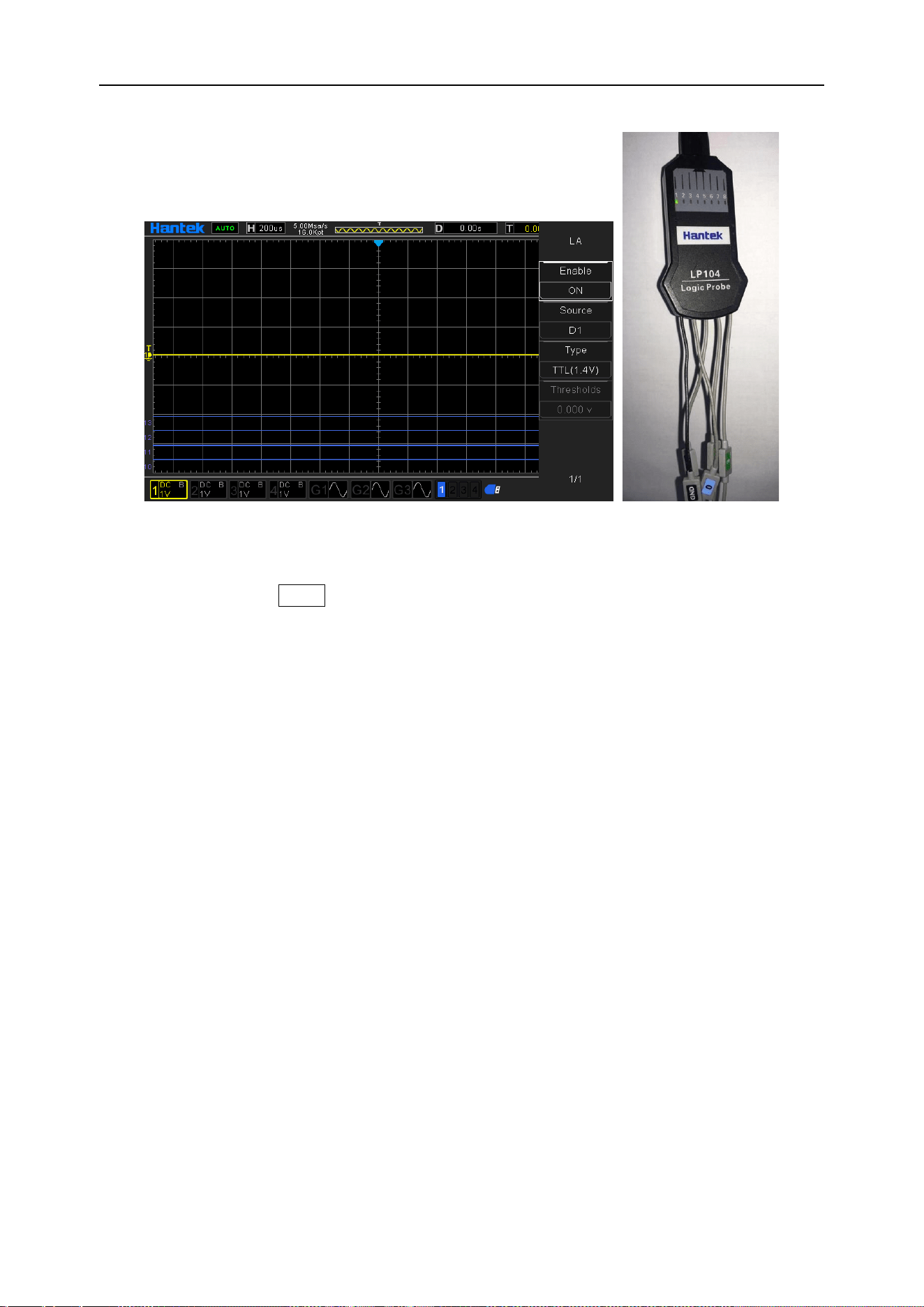
DPO6000, MPO6000 Series Digital Fluorescent Oscilloscope Product Manual V1.3
80
Set the digital channel thresholds type
Press the front panel Utility-> Logic Analyzer-> Type [TTL (1.4 V)]
5.0 V CMOS (+2.5 V)
3.3 V CMOS (+1.65 V)
2.5 V CMOS (+1.25 V)
1.8 V CMOS (+0.9 V)
ECL (-1.3 V)
PECL (+3.7 V)
LVDS (+1.2 V)
0V
User-defined [-7V~7V].
Waveform generator
The DPO6000C / MPO6000D has two built-in channels (MPO6000EDU has three built-
in channels) and a 25 MHz signal source. The signal source and oscilloscope are com-
bined into one, which greatly facilitates engineers who need to use the signal source
and oscilloscope at the same time. Built-in arbitrary waveform generator can output si-
ne, square wave, pulse, triangle wave, noise, DC, sampling wave, exponent, semi-
distortion, Lorentz, dual-tone multi-frequency, Gauss, ECG signal 13 kinds of basic sig-
nals, 4 groups of arbitrary waves. Users can edit and load arbitrary waveforms through

DPO6000, MPO6000 Series Digital Fluorescent Oscilloscope Product Manual V1.3
81
Wave Editor Software.
This chapter explains how to use the signal source built into the oscilloscope. Since the
functions and setting methods of the two / three channels of the signal source are the
same, this chapter uses signal source 1 as an example.
Press the button or click the WaveGen area on the screen to enter the source control
menu:
Output basic waveform
1. Select waveform
Push the front panel WaveGen-> Waveform.
2. Data source
Press WaveGen-> Data Source on the front panel.
3. Signal source channel
Press the front panel WaveGen-> Enable.
4. Frequency
Press WaveGen-> Frequency on the front panel.
5. Amplitude
Press the front panel WaveGen-> Amplitude.
Press the Amplitude soft key to set the amplitude of the current signal. When "Imped-
ance" is set to high impedance, the range can be set from 10mVpp to 7Vpp; when "Im-
pedance" is set to 50Ω, the range can be set from 5mVpp to 3.5Vpp.
6. Offset voltage
Press WaveGen-> Offset on the front panel.
Note: When "Impedance" is set to high impedance, the settable range is (-3.5 V + the
currently set amplitude value / 2) to (3.5 V-the currently set amplitude value / 2); when
"Impedance" is set to 50Ω, you can set the range from (-1.75 V + the currently set am-
plitude value / 2) to (1.75 V-the currently set amplitude value / 2).
7. Set the phase
Press WaveGen-> Phase on the front panel.
The adjustable range is 0 ° to 360 °.
8. Set the load impedance
Press the front panel WaveGen-> Load Impedance.

DPO6000, MPO6000 Series Digital Fluorescent Oscilloscope Product Manual V1.3
82
Load impedance can set the load input impedance of the signal source. You can
choose "High impedance" or "50Ω".
9. Align phase
Press WaveGen-> Align phase on the front panel.
After pressing “Align phase”, the signal source channel will be reconfigured so that it
will output according to the set frequency and phase. For two signals with the same
frequency or multiples, this operation can align their phases.
10. Modulation
Press the front panel WaveGen-> Modulation
For specific introduction to the modulation function, please refer to the section
"Modulation".
11. Burst
Press the front panel WaveGen -> Burst
For a detailed introduction to the burst function, please refer to the "Burst" section.
12. Duty
The duty is used only for square waves, and represents the amount of time the wave-
form is high during each cycle. It is 0.001% -99.996% at low frequencies and the range
will be reduced at higher frequencies.
13. Impedance
Impedance applies only to triangle waves, meaning that the triangle wave is the
amount of time to rise in each cycle.
14. Pulse width
Set the pulse width.
15. Pulse leading/trailing
Set the leading and trailing edges of the pulse wave.
Edit arbitrary waveform
Edit the arbitrary waveform in the oscilloscope's waveform generator interface. First,
double-click "Wave Editor Setup.exe" in the waveform editor folder on the CD-ROM
and install the arbitrary waveform editor according to the installation wizard. After suc-
cessful installation, the “WaveEditor” icon can be seen on the computer desktop. Dou-
ble-click the icon to enter the arbitrary waveform editing window.
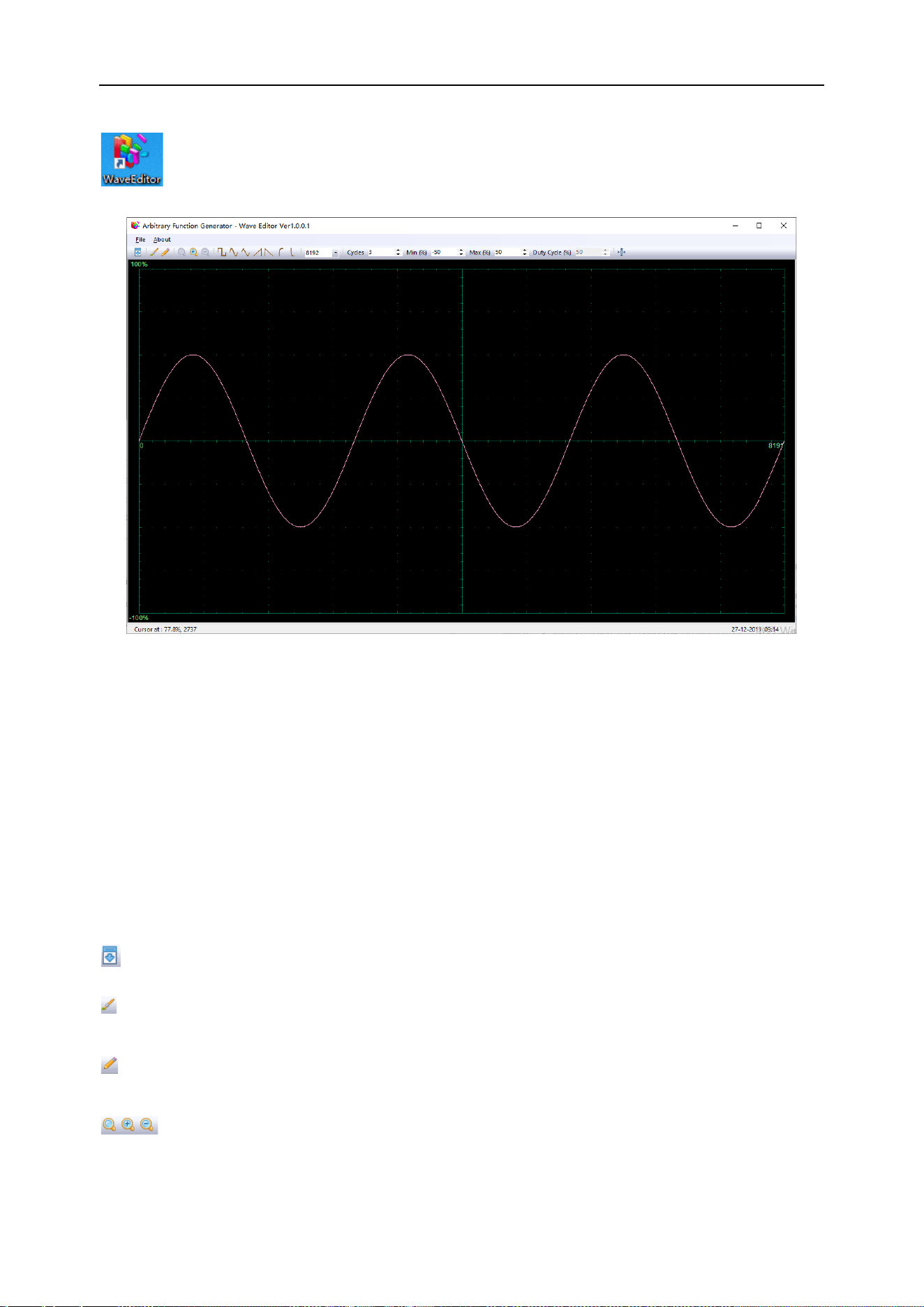
DPO6000, MPO6000 Series Digital Fluorescent Oscilloscope Product Manual V1.3
83
Menu:
Import from CSV file: Import CSV file to the arbitrary waveform editor interface.
Export as CSV file: Save the waveform data as a CSV file.
Import from ARB file: Import ARB file to the arbitrary waveform editor interface.
Export as ARB file: Save the waveform data as an ARB file.
Note: The device can recall the ARB file saved to the USB flash drive, but the CSV file
cannot be recalled.
Toolbar button
: Download the waveform data to the device.
: Smooth drawing mode. Use the left mouse button to draw an arbitrary shape wave-
form.
: Linear drawing mode. Click on the waveform to draw a straight line from the previ-
ous point.
: Zoom tool. Zoom in or out of the timeline. Click the “+” or “–” zoom button, and
then click the waveform area. Click the 100% button to restore the timeline to its origi-
nal scale.
DPO6000, MPO6000 Series Digital Fluorescent Oscilloscope Product Manual V1.3
84
: Standard waveform shape. Use the numeric controls below the
toolbar to draw standard waveforms according to the specified settings.
: Number of cycles. The number of waveform cycles. This control is used in
conjunction with standard waveform shape buttons. Select a standard waveform, and
then set the number of cycles to draw the waveform with the required number of cycles.
: Minimum value. This control sets the minimum signal level when the
standard waveform shape button is pressed.
: Maximum value. This control sets the maximum signal level when the
standard waveform shape button is pressed.
: Duty. This control sets the signal's duty when using the standard
waveform shape buttons to select square, triangle, or oblique. Duty is defined as the
time the signal is above zero volts divided by the total cycle time. Therefore, a symmet-
ric square or triangular wave has a 50% duty. Reducing the duty shortens the positive
part of the cycle and lengthens the negative part.
Note: When using the waveform editor software, the frequency, amplitude, and offset of
the arbitrary waveform cannot be adjusted, but after the waveform data is downloaded
to the device, you can directly set and adjust the device.
Do not use the waveform editor and oscilloscope software at the same time, otherwise
it will cause errors.
Output arbitrary wave
Output arbitrary waveform
1. Press the WaveGen button on the front panel to open the arbitrary waveform gen-
erator function and enter the waveform generator function menu.
2. Connect the device to a computer with WaveEditor software using a USB cable.
3. Use Keysight IO software to communicate with the WaveEditor. For specific opera-
tions, please refer to the description in the "Remote Control" section. You can also use
LAN or COM connection.
4. Double-click the WaveEditor icon to open the software.
5. Select a waveform file or draw an arbitrary waveform, click the icon on the toolbar,
and then select a waveform data download location to download the waveform to the
device.
DPO6000, MPO6000 Series Digital Fluorescent Oscilloscope Product Manual V1.3
85
6. The GEN OUT BNC port will output a waveform.
The user can also call up the .arb file in the USB storage device to output the waveform:
Press the [Wave Gen] button on the front panel to enter the waveform generator func-
tion menu.
Press the “Waveform” soft key, rotate V0 to select Arb1~Arb4, and then press V0 to
confirm.
Press the "Recall" soft key and select the .arb file to be recalled from the USB storage
device.
Modulation
The built-in signal source of DPO6000 / MPO6000 series oscilloscopes supports AM,
FM, PM, and PWM modulation functions. The modulated waveform consists of a carrier
wave and a modulated wave. The carrier signal is a waveform signal output by the sig-
nal source, and the modulation signal can be selected from the built-in sine wave,
square wave, and triangle wave.
Amplitude modulation
Amplitude Modulation (AM), that is, the amplitude of the carrier wave changes with the
modulation wave.
1. Turn on the modulation function
Press WaveGen-> Modulation-> Modulation on the front panel.
2. Set AM modulation
Press WaveGen-> Modulation-> Type on the front panel and select AM.
3. Set the modulation waveform
Press the front panel WaveGen-> Modulation-> Waveform Sine, Square, and Triangle.

DPO6000, MPO6000 Series Digital Fluorescent Oscilloscope Product Manual V1.3
86
4. Set the modulation frequency
Press WaveGen-> Modulation-> Frequency on the front panel.
5. Set the modulation depth
Press WaveGen-> Modulation-> Depth on the front panel.
Frequency modulation
Frequency modulation (FM), that is, the frequency of the carrier wave changes with the
modulation wave.
1. Turn on the modulation function
Press WaveGen-> Modulation-> Modulation on the front panel.
2. Set FM modulation
Press WaveGen-> Modulation-> Type on the front panel and select FM.
3. Set the modulation waveform
Press the front panel WaveGen-> Modulation-> Waveform Sine, Square, and Triangle
4. Set the modulation frequency
Press WaveGen-> Modulation-> Frequency on the front panel.
5. Set the modulation frequency offset
Press WaveGen-> Modulation-> Deviation on the front panel.
Phase modulation
The modulated waveform of Phase Modulation (PM) usually consists of a carrier wave
and a modulated waveform. The phase of the carrier wave changes with the instanta-
neous voltage of the modulated waveform.
1. Turn on the modulation function
Press WaveGen-> Modulation-> Modulation on the front panel.
2. Set PM modulation
Press WaveGen-> Modulation-> Type on the front panel and select PM.
3. Set the modulation waveform
Press the front panel WaveGen-> Modulation-> Waveform Sine, Square, and Triangle.
4. Set the modulation frequency
Press WaveGen-> Modulation-> Frequency on the front panel.

DPO6000, MPO6000 Series Digital Fluorescent Oscilloscope Product Manual V1.3
87
5. Set the modulation frequency offset
Press WaveGen-> Modulation-> Deviation on the front panel.
Pulse Width modulation
The modulated waveform of the Pulse Width Modulation (PWM) consists of a carrier
wave and a modulation waveform, and the pulse width of the carrier wave changes with
the instantaneous voltage of the modulation waveform.
1. Turn on the modulation function
Press WaveGen-> Modulation-> Modulation on the front panel.
2. Set PWM modulation
Press WaveGen-> Modulation-> Type on the front panel and select PWM.
3. Set the modulation waveform
Press the front panel WaveGen-> Modulation-> Waveform Sine, Square, and Triangle.
4. Set the modulation frequency
Press WaveGen-> Modulation-> Frequency on the front panel.
5. Set the modulation depth
Press WaveGen-> Modulation-> Depth on the front panel.
Burst
The DPO6000 / MPO6000 can output waveforms with a specified number of cycles.
1. Enable the burst function
Push the front panel WaveGen-> Burst.
2. Set the count value
Press WaveGen-> Burst-> Count on the front panel.
3. Set the data source
Press WaveGen-> Burst-> Data Source on the front panel to select Manual, Pass / Fail,
DSO Trigger.
Manually:
The manual trigger source controls the burst output. At this time, the “Trigger” button is
optional. Pressing “Trigger” once, the signal source outputs a waveform with a set
number of cycles.
Pass failed:

DPO6000, MPO6000 Series Digital Fluorescent Oscilloscope Product Manual V1.3
88
Run the [Pass / Fail] test, turn on the "Output" and select "Output to DDS", the system
will automatically turn on the "Burst" switch under the corresponding signal source, and
the "Count" defaults to 1. According to the test results, the specified signal source out-
puts a waveform with a set number of cycles.
DSO Trigger:
Each time the waveform in the oscilloscope triggers, the current signal source outputs a
waveform with a set number of cycles.
Pass / Fail test
The pass / fail test function is mainly used to evaluate the signal quality. By setting rules
in the oscilloscope to test the waveforms in real time, counting the number of tests with-
in the specified test conditions, the number of pass / fail data frames, and displaying
the test results.
Enable pass / fail test
Press [Utility] -> "Pass / Fail"-> “Enable test”->"On" to enable the test function. The
shaded area indicates the failure area. If the waveform measured at a time during the
measurement passes through the failure area, it is determined as a failure frame.
Note: When the Time Mode is set to X-Y mode, ROLL mode or the horizontal time base
is set to 200 ms / div or slower in YT mode, when the instrument enters the "slow scan"
mode, this function cannot be enabled.
1. Data source
Before selecting the data source, you need to connect the signal under test to the ana-
log channel input of the oscilloscope. Press the "Data Source" soft key to select the
channel (CH1-CH4) to be tested. Note: Only channels that are already open can be se-
lected.
2. Rule
Users can customize the rules for pass / fail tests. Press the "Horizontal" and "Vertical"
soft keys respectively, rotate V0 to adjust the pass / fail rule. Press the "Create" soft key
to apply the current rule. The oscilloscope prompts "Mask created!".
3. Test and output
The user can set the output format of the test results as follows.
Press the Message soft key to select whether to display the test results.
Press the Stop On Output soft key and select On or Off.
On: When the oscilloscope detects a waveform that matches the set “Mode”, the test
stops immediately and enters the STOP state. The information displayed on the screen
at this time is the statistical result as of STOP. If “On” is selected for “Output”, the pulse

DPO6000, MPO6000 Series Digital Fluorescent Oscilloscope Product Manual V1.3
89
displayed on the rear panel [Aux Port] will disappear immediately.
Off: When the oscilloscope detects a waveform that matches the set “Mode”, the test
continues. The information displayed on the screen continues to update in real time. If
“On” is selected for “Output”, the [Aux Port] on the rear panel will output a pulse.
Press the Output soft key to select whether to output the test results. When the oscillo-
scope detects a waveform that matches the set “mode”, the Aux port on the rear panel
outputs a waveform; when it does not detect a waveform that matches the set “mode”,
there is no output.
Press the Mode soft key:
Pass: When a pass is detected, the statistical results and output pulses are displayed,
and the buzzer does not alarm.
Failure: When a failure is detected, the statistical results and output pulses are dis-
played, and the buzzer does not alarm.
Pass ring: When one pass is detected, the statistical result and output pulse are dis-
played, and the buzzer alarms (not related to the sound switch state).
Failure ring: When a failure is detected, the statistical result and output pulse are dis-
played, and the buzzer alarms (not related to the sound switch state).
Press the Output to DDS soft key to select the test result output path.
Select the output to the signal source (GEN1 / GEN2 / GEN3, the oscilloscope auto-
matically turns on the burst enable of the corresponding signal source, and set the
"Source" to "Pass / Fail", the user only needs to manually enable the corresponding
signal source to enable) or directly Output from the AUX port on the rear panel (off, the
user need to manually set "Utility"-> "AUX" to select Pass / Fail).
For the setting of the signal source, please refer to section Burst.
Segmented acquisition
Segmented storage when multiple triggers are made in the acquisition process, the da-
ta obtained for each trigger sampling is stored in the storage space of each segment.
Segment storage principle
As shown in the figure below, the data collected when the first trigger occurs is stored
in the first segment of storage space, the data collected when the second trigger occurs
is stored in the second segment of storage space, and so on, until When the number of
segments set by the user is acquired, the oscilloscope enters the pause state to end
the acquisition process. Read the first segment of the acquisition for display.
DPO6000, MPO6000 Series Digital Fluorescent Oscilloscope Product Manual V1.3
90
Acquisition 1 Acquisition 2 Acquisition 3 Acquisition 4 Acquisition n
≤memory depth
Trigger 1 Trigger 2
Trigger 3
Trigger 4 Trigger n
The MPO6000EDU oscilloscope is taken as an example. The total storage depth is
128Mpts. The formula for calculating the number of segments is as follows:
N=128*1024*1024/ [round the current storage capacity to 2
n
] -1.
Segment settings
The maximum storage of MPO6000EDU oscilloscope is 128Mpts. With the 1GSa / s
sampling rate, the segment storage range is supported: 1~80,000 segments, and the
maximum length of a single segment is 32K.
1. Enable segmented acquisition
Utility-> Acquisition-> Segmented Acquisition-> Segmented Acquisition
2. Set the number of segmented acquisition segments
Utility-> Acquisition-> Segmented Acquisition-> Segmentation Setting: Set the number
of segments for segmented acquisition
3. Set the segmented collection to view the segment value
Utility-> History Waveform-> Frames: Set the waveform display screen to display the
corresponding frame number after the segment acquisition is finished.
4. Open and close the list
Utility-> History Waveform-> List: Turn on / off the segmented acquisition list function.
Please turn on the segmented storage function before opening the list.
History waveform
When the user starts to use the oscilloscope, the oscilloscope will automatically acquire
and store data, which can collect up to 80,000 frames. Open history waveforms to ob-
serve previously stored waveforms and perform measurement analysis on them. Users
can also capture individual details or waveforms that change over time by setting time
intervals and waveform navigation at different speeds. Each record is indexed by a time
stamp, and the history waveform function can record the input waveform for a period of
time before STOP.
The waveform playback function can play the currently recorded waveform. During
playback, the information shown in the figure below will be displayed in the upper right

DPO6000, MPO6000 Series Digital Fluorescent Oscilloscope Product Manual V1.3
91
corner of the screen. The data on the left of the figure is the specific frame displayed on
the current screen. During playback, this value is constantly changing. The data on the
right indicates the maximum number of frames that have been recorded.
After enabling the segment acquisition function, press to manually play the next
frame; press the automatic sequence to play the segment acquisition waveform.
The playback interval can be set by the interval. The minimum value of the automatic
playback interval is 10ms; press to pause the automatic playback; Press to play
the previous frame manually.
Display control
Users can set the waveform display type, persist time, waveform brightness, grid type
and grid brightness displayed on the screen, and the color display type of the waveform.
Display type
Press Display-> Display Type to set the waveform display mode to "Vector" or "Dot".
Vector display: The sampling points are displayed by connecting lines. This mode pro-
vides the most realistic waveform in most cases. Easily view the steep edges of a
waveform, such as a square wave.
Point display: directly display the sampling point. The user can see each sampling
point intuitively and can use the cursor to measure the X and Y values of that point.
Grid
Press Display-> Screen Grid to set the screen grid type.
1. Show only vertical and horizontal center grid
2. Show only vertical and horizontal center grids, and use dot display to draw other hor-
izontal and vertical grids
3. Show only vertical and horizontal center grids, and use line display to draw other
horizontal and vertical grids
Waveform brightness
Press Display-> Waveform Brightness, or in the case of non-menu operation, turn V0 to
adjust the waveform brightness value of the channel. The default is 50% and the ad-
justable range is from 0% to 100%.
Grid Brightness
Press Display-> Grid Brightness to set the screen grid brightness. Turn V0 to adjust the

DPO6000, MPO6000 Series Digital Fluorescent Oscilloscope Product Manual V1.3
92
grid brightness. The default is 50% and the adjustable range is from 1% to 100%.
Screen brightness
Press Display-> Screen Brightness to set the screen brightness. Turn V0 to adjust the
grid brightness. The default is 80% and the adjustable range is from 1% to 100%.
Color grade
The color grade function uses the color change to reflect the frequency of waveform
appearance. The more frequently the waveform appears, the warmer the color. The
less frequent it appears, the cooler the color. The picture below is a gradient picture of
cool and warm colors.
Press Display-> Color grade on the front panel and select “On” to enable the color
grade function. You can compare the color of the currently displayed waveform with the
figure below to determine the probability of the waveform appearing.
Warm color
Cold color
Persist time
Press Display-> Persist Time to set the oscilloscope’s persist time to the minimum val-
ue, specific value (minimum value, 1 s, 5 s, 10s, and 30 s) or infinite. The following us-
es sine wave sweep signals to demonstrate the waveform effect under different persist
times.
1. Minimum value
Observe waveforms that change at high refresh rates.
2. Specific value
Observe glitches that change more slowly or appear less prone. The afterglow time can
be set to: 1s, 5s, 10s, and 30s.
3. Infinite
When the oscilloscope displays a newly acquired waveform, it will not clear the previ-
ously acquired waveform. The acquired waveform is displayed in a lower brightness
color, and the newly acquired waveform is displayed in normal brightness and color.
Use infinite persistence to measure noise and jitter and capture infrequent events.

DPO6000, MPO6000 Series Digital Fluorescent Oscilloscope Product Manual V1.3
93
Store and recall
Users can save the current oscilloscope settings, waveforms, reference waveforms,
CSV files, and screen images in various formats in the internal flash memory or USB
storage device. The reference waveform can be compared with other waveforms to de-
termine the cause of the failure.
Save
Save type
1. Set
Save the oscilloscope settings to internal memory or external memory, the format is .set.
2. Waveform (binary)
Save the oscilloscope waveform to internal memory or external memory, the format
is .lwf.
3. Reference waveform
Save the oscilloscope reference waveform to internal memory or external memory, the
format is .ref.
4. CSV
Save the waveform data to the external memory, you can specify the file name and
save path, the format is .csv. The storage file contains the waveform data of the display
channel and the main setup information of the oscilloscope.
Save directory
The storage path includes internal flash memory and external storage. The internal
flash memory can store up to 9 files (No. 1 to No. 9). The external storage can specify
the file name and the storage path. In addition to CSV files, saved files can be recalled.
Recall
Recall type
1. Set
Recall the .set setting file from the internal or external memory of the oscilloscope.
2. Waveform (binary)
Recall the .lwf waveform file from the internal or external memory of the oscilloscope.
3. Reference waveform

DPO6000, MPO6000 Series Digital Fluorescent Oscilloscope Product Manual V1.3
94
Recall the .ref reference waveform file from the internal or external memory of the oscil-
loscope.
Recall directory
The recall path includes internal flash memory and external memory. The internal flash
memory can recall up to 9 files (No. 1 to No. 9), and the external memory can specify
the file name and path to recall.
Utility function
Language
This oscilloscope provides Chinese and English help information, prompt information,
and interface display. Press Utility -> Language, turn the multi-function knob to select
the desired language, and press the multi-function knob to select the language.
Touch screen
This oscilloscope supports manually switching the touch screen. Press Utility-> touch
screen to switch the touch screen.
System information
Press Utility-> System Information to view the user's oscilloscope system information.
System information includes manufacturer, model, serial number, and software and
hardware version numbers.
Pass failed
In the pass / fail test, when the oscilloscope detects a waveform that meets the pass /
fail rule and output mode, it will output a pulse through the Aux port on the rear panel
([Function Reuse] select “Pass / Fail”); When the waveform of the above conditions
fails, there is no output from this port. For a detailed introduction of the pass / fail test
function, please refer to the description in “Pass / Fail Test”.
Upgrade firmware
DPO6000 / MPO6000 can upgrade firmware through USB storage device. The whole
process takes about 3 minutes.
Please upgrade the oscilloscope as follows:
1. Insert the storage device into the USB Host interface on the front panel.
2. Press Utility-> Upgrade-> Upgrade Firmware-> Manually select the firmware file->

DPO6000, MPO6000 Series Digital Fluorescent Oscilloscope Product Manual V1.3
95
Start the upgrade process.
3. Use multi-function knob V0 to select the .upk file to be upgraded, and press multi-
function knob V0 to select the upgrade file.
4. After the upgrade is completed, a prompt message will pop up on the screen to re-
mind the user that the upgrade has been successful and the oscilloscope will restart
automatically.
5. Press the F5 back key to cancel the upgrade.
Calibration
Performing the calibration procedure can quickly make the oscilloscope reach the best
working condition to obtain the most accurate measurement value. The user can exe-
cute the program at any time, especially when the ambient temperature variation range
reaches or exceeds 5 ° C. Before performing the self-calibration operation, make sure
that the oscilloscope has been warmed up or run for more than 30 minutes. Disconnect
all input channels and press Utility-> Calibration.
AUX
Press Utility -> AUX to set the type of signal output from the Aux port on the rear panel.
Trigger output
The oscilloscope generates a trigger, and the interface will output a signal reflecting the
current capture rate of the oscilloscope. Connect this port to the waveform display de-
vice to measure the frequency of the output signal. The measurement result is the
same as the current capture rate.
Pass / fail
When the oscilloscope tests a waveform that meets the pass / fail rule and output mode,
it will output a pulse signal. For details, please refer to the introduction in "Pass / Fail
Test".
System settings
Sound
Press Utility-> System Settings-> Sound. After turning on the sound, you can hear the
buzzer sound when operating the menu or popping up a prompt message. Sound is
turned on by default.
DPO6000, MPO6000 Series Digital Fluorescent Oscilloscope Product Manual V1.3
96
Network
Wlan0
"Status", "DHCP", “Auto IP” select "On" to search for nearby wireless networks and
display them in the "Scan Results" list on page 3. Use the V0 knob to select the wire-
less network to be connected, press the button to confirm, or manually enter the wire-
less network name, enter the password in "PSK", and press "OK". At this time, the
screen displays "WIFI is connected", and the lower right corner of the screen a blue
WIFI icon is displayed.
You can control the oscilloscope on the PC by searching for the IP address of the oscil-
loscope on the wireless network PC browser.
The PC browser display interface is as follows:
Hot spot
Select "wlan0" for the network, "On" for "Status" and "DHCP", and "On" for the "Hot"
status. The gray WIFI icon is displayed in the lower right corner of the screen. When a
user successfully connects to the hotspot, the number of current users is displayed in
the WIFI icon.
The client can set the IPv4 address manually or automatically. The client's IP address
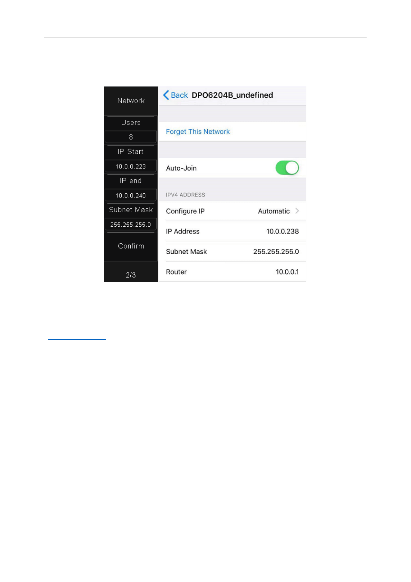
DPO6000, MPO6000 Series Digital Fluorescent Oscilloscope Product Manual V1.3
97
should be set in the starting IP and ending IP segments. The subnet mask and router
settings are the same as the oscilloscope.
Eth0
"Network" select "eth0" to set the network port communication to remotely control the
oscilloscope. For the setting procedure, please refer to “Control via LAN” under
“Remote Control”.
Time
Set the year, month, day, hour, minute, and second.
Touch calibration
Follow the prompts to calibrate the touch screen.
Self-test and front-panel self-test
Self-test and front-panel self-test include screen test, keyboard test, and lighting test. It
is mainly used to check whether there are mechanical problems with the oscilloscope,
such as the display color deviation, the response sensitivity of the buttons and knobs,
and whether the button lights are on.
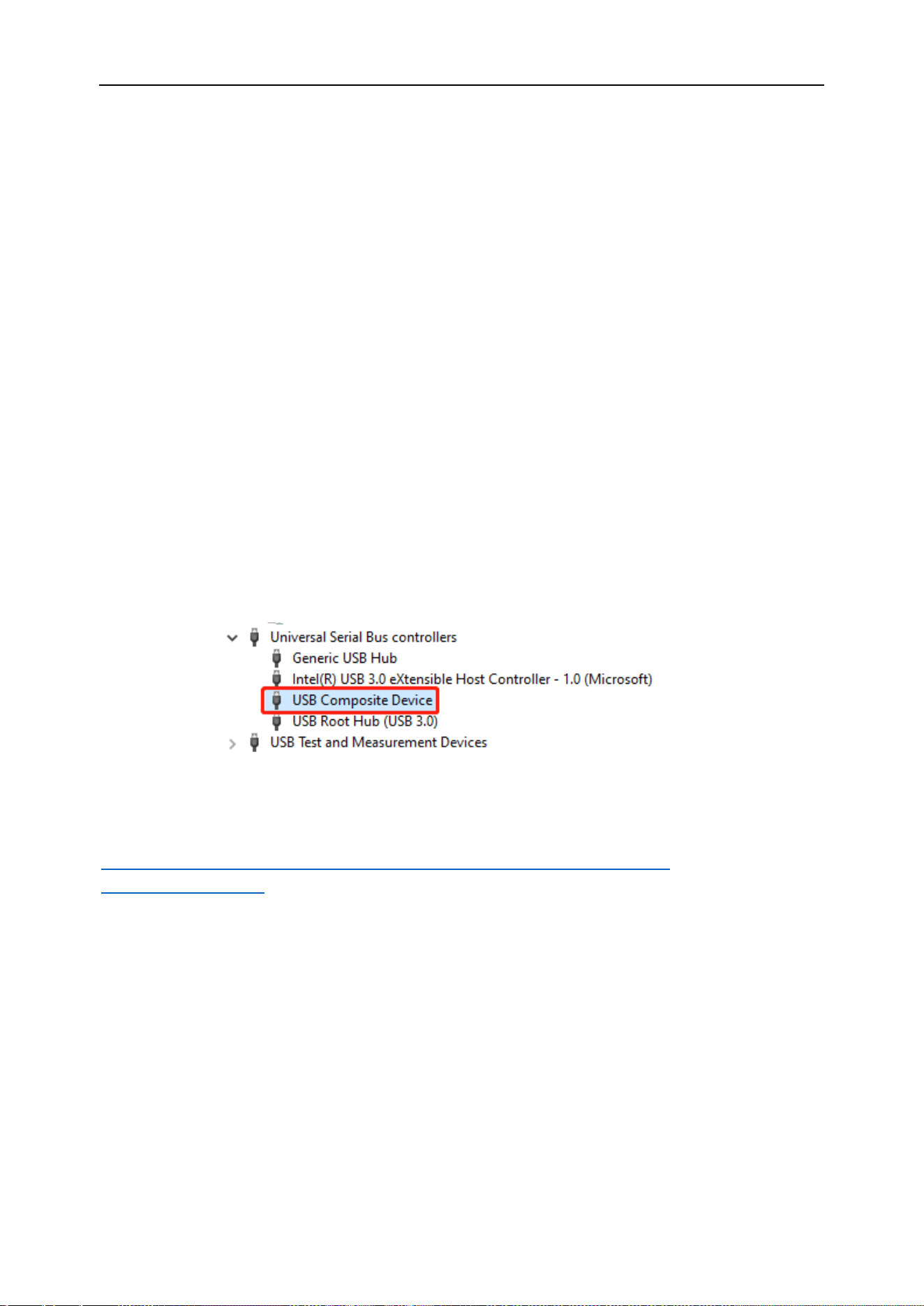
DPO6000, MPO6000 Series Digital Fluorescent Oscilloscope Product Manual V1.3
98
Conditional Search
The condition search function is used to search for the position that meets the trigger
condition after the trigger point after the waveform trigger, and is identified by the lower
triangle symbol.
Remote control
There are three main ways to remotely control the oscilloscope:
1. Control via USB
2. Control via LAN
3. Control via serial port
Control via USB
Use a USB data cable to connect the USB Device interface on the rear panel of the os-
cilloscope with the USB interface of the computer. A new device will display in device
manager.
Install the IO software (Keysight IO libraries suite):
Click the following URL to download the latest software:
https://www.keysight.com/main/software.jspx?ckey=2175637&lc=chi&cc=CN&nid=-
11143.0.00&id=2175637
Double-click the application to begin installation. Follow the installation prompts to in-
stall step by step. The installation process may take several minutes.
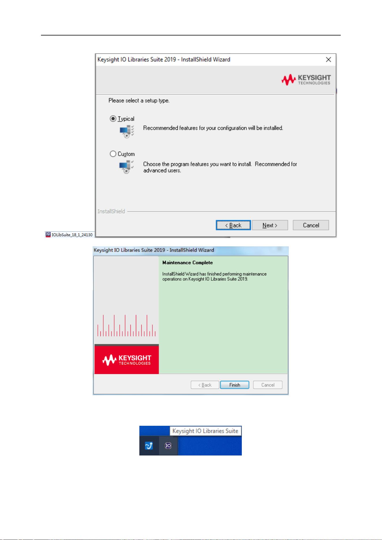
DPO6000, MPO6000 Series Digital Fluorescent Oscilloscope Product Manual V1.3
99
You can see the running IO software in the lower right corner of the screen after the in-
stallation is complete.
Double-click to open the IO software; you can see the connected device information
displayed under My Instrument-USB.
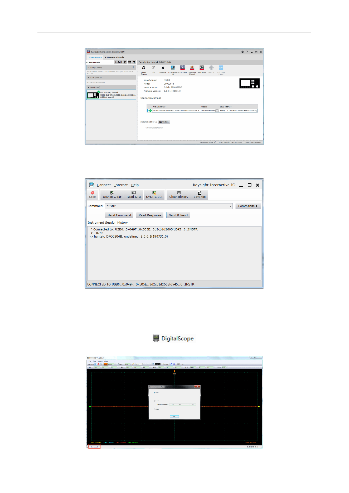
DPO6000, MPO6000 Series Digital Fluorescent Oscilloscope Product Manual V1.3
100
Click "Interactive IO"; send any command, the computer and the oscilloscope get
communication.
Double-click to open the host computer software, click File-> Connection-> Connection
Method, and select USB connection. At this time, the lower left corner of the host com-
puter software is displayed as connected.
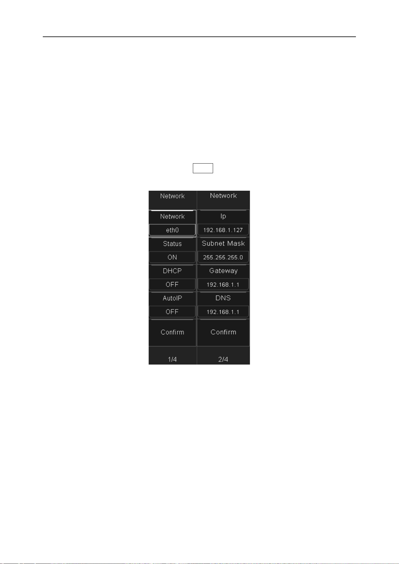
DPO6000, MPO6000 Series Digital Fluorescent Oscilloscope Product Manual V1.3
101
At this point, the oscilloscope screen displays "Keyboard lock. Press the help key three
times to unlock the keyboard." If you want to control the oscilloscope by pressing keys,
you need to close the host computer software first and press Help three times to unlock
the keyboard.
Control via LAN
Use a network cable to connect the network port on the back panel of the oscilloscope
to the network port on the computer. The network cable connected icon is displayed in
the lower right corner of the oscilloscope screen.
Set the oscilloscope network parameters: Utility-> System Settings-> Network set the
corresponding IP address, subnet mask, gateway, DNS and confirm.
Set the computer network parameters: Open Network Connections-> Status-> Change
your network settings-> Change adapter options->Ethernet-> Properties-> Internet Pro-
tocol Version 4 (TCP / IPv4), set the computer's IP address to 192.168.1.2 or other
(192.168.1.2~192.168.1.255) except Any IP other than the oscilloscope IP (default IP
is 192.168.1.127), the subnet mask is set to the default value.
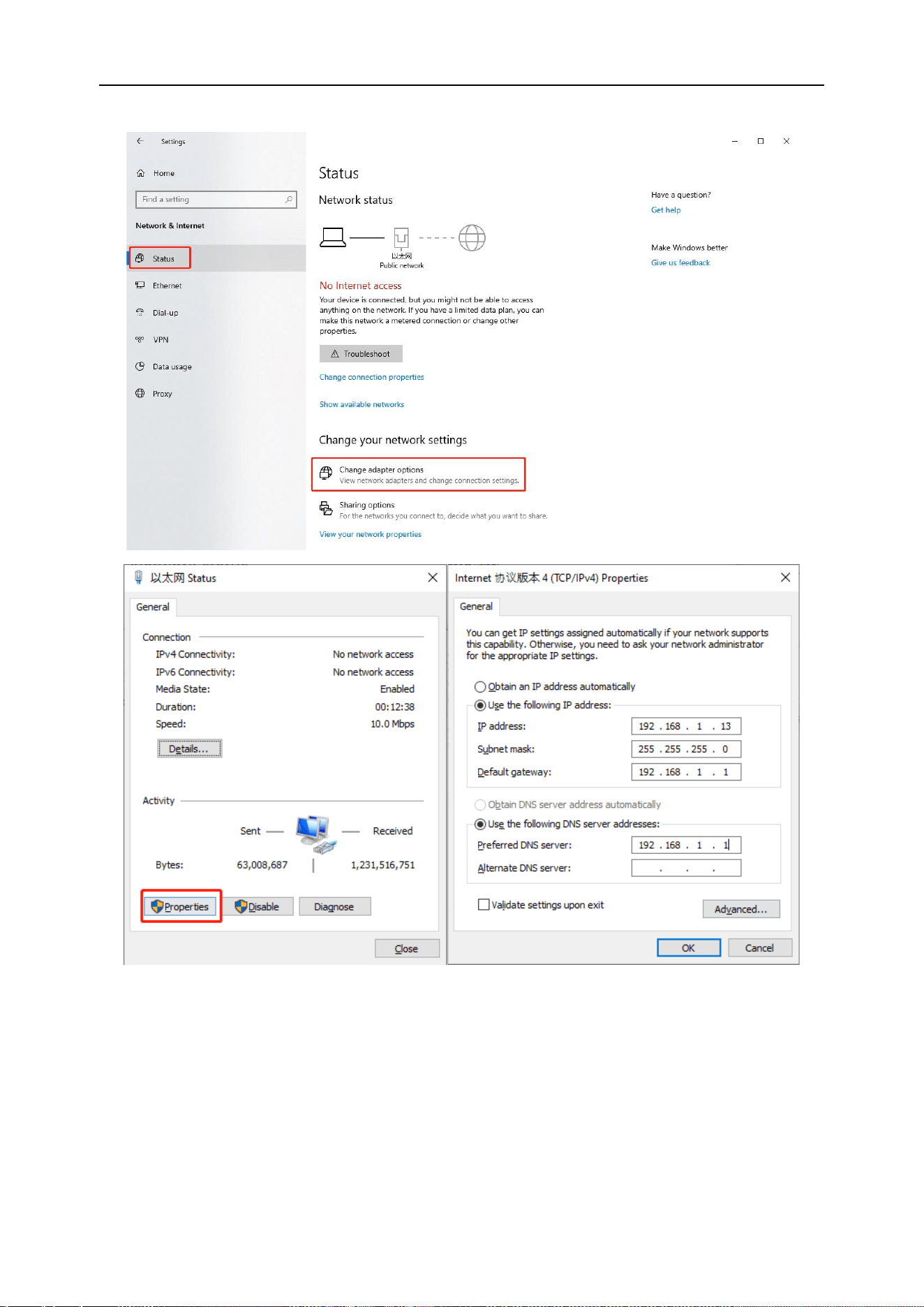
DPO6000, MPO6000 Series Digital Fluorescent Oscilloscope Product Manual V1.3
102
Double-click to open the IO software and select the recognized device.
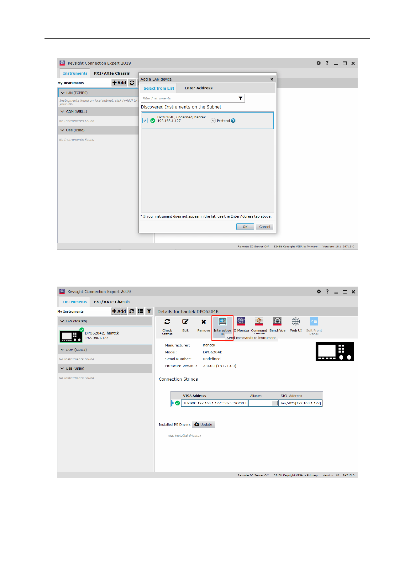
DPO6000, MPO6000 Series Digital Fluorescent Oscilloscope Product Manual V1.3
103
Click "Interactive IO", send any command, the computer and the oscilloscope get
communication.
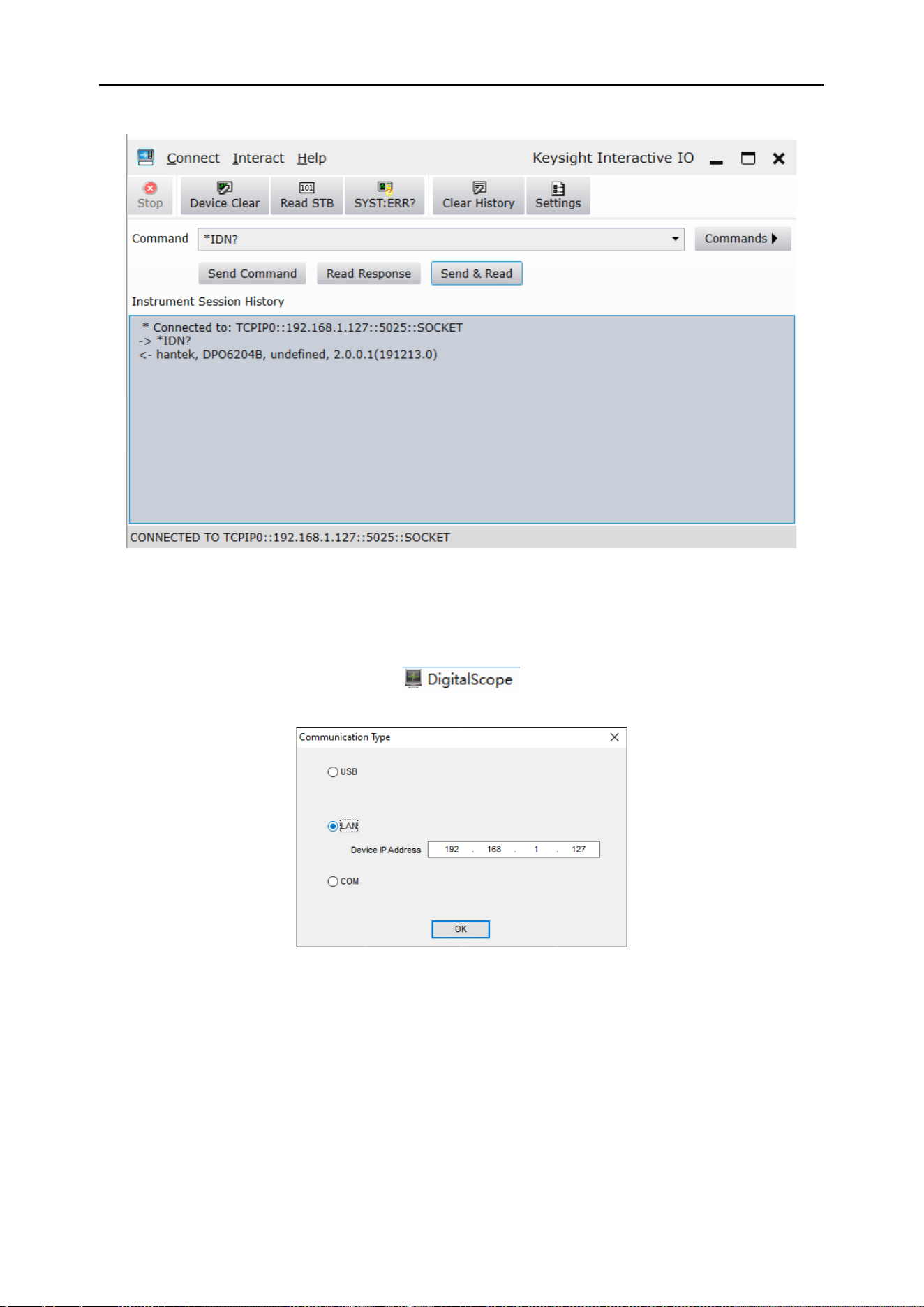
DPO6000, MPO6000 Series Digital Fluorescent Oscilloscope Product Manual V1.3
104
Double-click to open the PC software, click File-> Connection-> Connection Method,
and select LAN connection. At this time, the lower left corner of the host computer soft-
ware is displayed as connected.
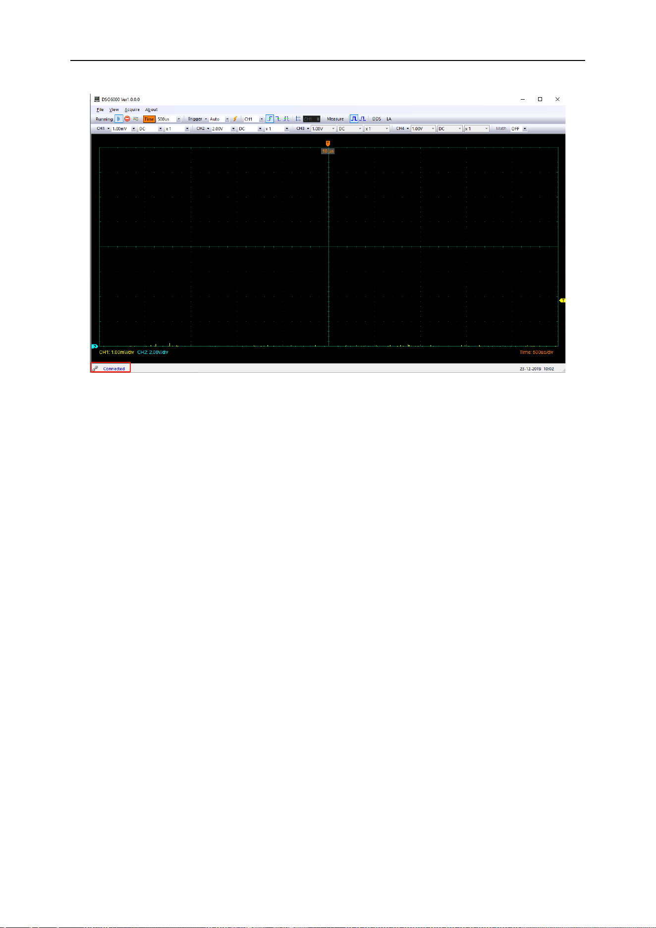
DPO6000, MPO6000 Series Digital Fluorescent Oscilloscope Product Manual V1.3
105
At this point, the oscilloscope screen displays "Keyboard lock. Press the help key three
times to unlock the keyboard." If you want to control the oscilloscope by pressing keys,
you need to close the host computer software first and press Help three times to unlock
the keyboard.
Control via serial port
Connect the network port of the network port to serial cable to the network port on the
rear panel of the oscilloscope, and connect the serial port to the computer.
Open the IO program, select "Add Device" and set the serial port properties. The baud
rate is 115200.

DPO6000, MPO6000 Series Digital Fluorescent Oscilloscope Product Manual V1.3
106
The IO software "My instrument" COM list shows the connected devices, click "interac-
tive IO", and send any command, the computer and the device get communication.
Double-click to open the host computer software, click File-> Connection-> Communi-
cation type, and select COM connection. At this time, the lower left corner of the host
computer software is displayed as connected.
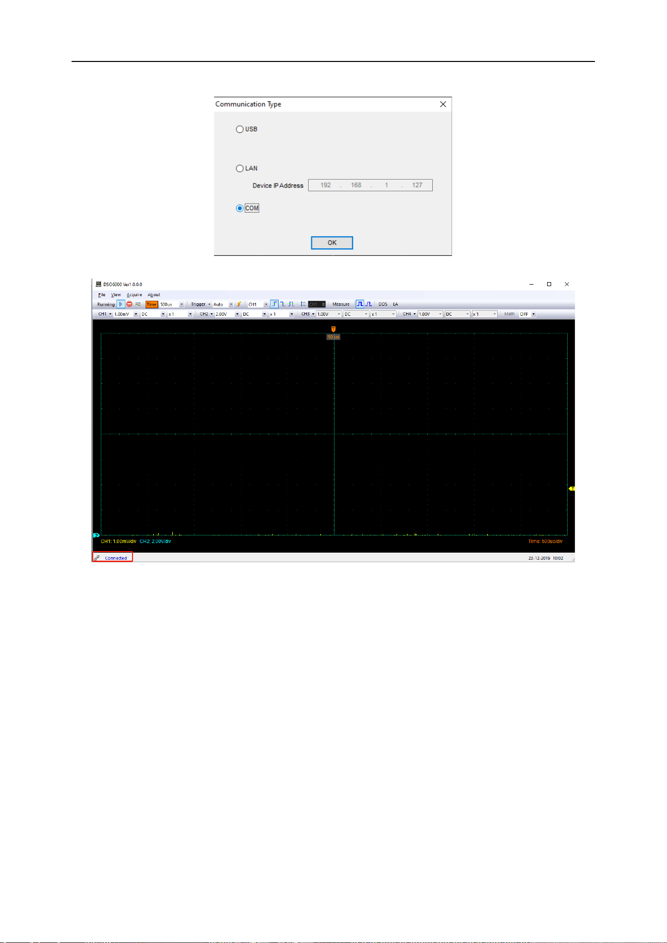
DPO6000, MPO6000 Series Digital Fluorescent Oscilloscope Product Manual V1.3
107
At this point, the oscilloscope screen displays "Keyboard lock. Press the help key three
times to unlock the keyboard." If you want to control the oscilloscope by pressing keys,
you need to close the host computer software first and press Help three times to unlock
the keyboard.
Common faults and solutions
1. The oscilloscope does not turn on after pressing the power switch
(1) Check whether the power cord on the side of the oscilloscope is connected normally.
(2) Check if the power switch is pressed.
(3) After completing the above inspections, turn on the instrument again.
If the oscilloscope still does not turn on normally, please contact your local dealer or di-
rectly contact Hantai Technical Support.

DPO6000, MPO6000 Series Digital Fluorescent Oscilloscope Product Manual V1.3
108
2. No waveform is displayed on the input signal screen after the oscilloscope is
turned on.
(1) Check whether the oscilloscope probe is correctly connected to the BNC connector
of the signal input channel.
(2) Check whether the channel switch is on (CH1~CH4 menu button).
(3) Check whether the input signal is correctly connected to the probe.
(4) Check if there is signal output from the measured circuit.
(5) If it is a DC signal and the amplitude is relatively large, please increase the ampli-
tude.
(6) You can press the automatic measurement button to automatically detect the signal
first.
If there is still no waveform display, please contact Hantai Technical Support in time.
3. The input signal waveform distortion is serious
(1) Check if the oscilloscope probe is connected to the channel BNC connector.
(2) Check whether the probe is well connected with the measured object.
(3) Check whether the oscilloscope probe is calibrated properly. If there is no calibration,
please calibrate according to the relevant content in the manual.
4. The waveform continuously scrolls on the screen and cannot be triggered.
(1) Check whether the trigger data source is consistent with the signal input channel.
(2) Check whether the trigger level is adjusted correctly. You can press the trigger level
knob to return the trigger level to the signal center point.
(3) Check whether the trigger mode is correct, because the default trigger is edge trig-
ger. For different input signals, the trigger mode should be selected correctly.
Technical specifications
All technical specifications are applicable to the DPO600 / MPO6000 series digital stor-
age oscilloscopes. For details, see the last part of this chapter. To verify that the oscillo-
scope meets the technical specifications, the oscilloscope must first meet the following
conditions:
➢ The oscilloscope must have been working continuously for more than 20 minutes
within the specified operating temperature.
➢ If the operating temperature changes by more than 5 degrees Celsius, you must
perform the “self-calibration” operation. This operation can be performed through
the [Utility] menu.

DPO6000, MPO6000 Series Digital Fluorescent Oscilloscope Product Manual V1.3
109
➢ The oscilloscope must fall within the factory calibration period.
All specifications are guaranteed to meet the requirements except those marked as
"Typical."
Oscilloscope technical specifications
Acquire
Acquisition meth-
od
Normal, average, peak, high resolution
Real-time
sampling rate
1 G Sa/s (single channel)
500 M Sa/s (dual channel)
250 M Sa/s (three / four channels);
Peak Detect
Analog Channel 4ns
Averaging mode
N samples for analog channels (N values: 2, 4, 8, 16, 32, 64, 128, 256,
512, and 1024)
High resolution
12bit
Minimum detection
pulse width
8ns
Memory Depth
Single Channel 64M / 128M [EDU]
Dual channel 32M / 64M [EDU]
Three or four channels 16M / 32M [EDU]
Input
Number of chan-
nels
4 analog channels, 16 (4 * 4) digital channels
The number of analog and digital channels opened at the same time
should be less than 4.
Input coupling
DC, AC or GND
Digital channels are not supported
input resistance
DC coupling
Analog channel: 25pF ± 3pF, 1MΩ ± 2%
Digital channels: (300KΩ ± 2%), (8 pF ± 3 pF)
Support probe at-
tenuation coeffi-
cient
Analog channels 0.01X, 0.02X, 0.05X, 0.1X, 0.2X, 0.5X, 1X, 2X, 5X, 10X,
20X, 50X, 100X, 200X, 500X, 1000X, 2000X, 5000X, 10000X
Voltage rating
300V CAT II

DPO6000, MPO6000 Series Digital Fluorescent Oscilloscope Product Manual V1.3
110
300V CAT II
Input voltage
Analog channels 300VRMS (10X)
Digital channel-25V~25V
Horizontal
Waveform Interpo-
lation
Sine, Linear, Step
Horizontal scale
2ns/div~100s/div 1,2,5 steps
Time base mode
Y-T, X-Y, Roll
X-Y number
1, 2 channel combination 1 XY
3, 4 channels combined 1 XY
Zero offset
± 0.5 div × minimum time base scale
Sampling rate and
delay time accura-
cy
±25ppm
Clock drift
≤±5 ppm/year
Incremental time
measurement ac-
curacy (Full band-
width)
single shot, "sampling" mode
± (1 sampling interval + 100ppm × reading + 0.6ns)
> 16 times average
± (1 sampling interval + 100ppm × reading + 0.4ns)
Sampling interval = seconds / div ÷ 200
Vertical
Bandwidth (-3db)
DPO6084
DPO6104
DPO6204
80MHz
100MHz
200MHz
Vertical resolution
Analog channel 8bit
Digital channel 1bit
Vertical scale
500μV/div~10V/div at input BNC
Position range
500μV/div to 120mV/div, ±1V
122mV/div to 1.2V/div, ±10V
1.22V/div to 10V/div, ±50V

DPO6000, MPO6000 Series Digital Fluorescent Oscilloscope Product Manual V1.3
111
Selectable analog
bandwidth limit,
typically
20MHz
Low frequency
response (-3db)
≤10Hz at BNC
Rise time at BNC,
typical
DSO6084
DSO6104
DSO6204
≤4.4ns
<3.5ns
≤1.8ns
Vertical gain accu-
racy
In the "normal" or "average" acquisition mode, the accuracy from 10V/div
to 10mV/div is ± 3%.
In "normal" or "average" acquisition mode, the accuracy from 5mV/div to
500uV/div is ± 4%.
DC offset accura-
cy
± 0.1div ± 2 mV ± 1% offset value
Channel Isolation
DC to Maximum Bandwidth:> 40 dB
Note: The bandwidth is reduced to 6MHz when using the X1 probe
Vertical (digital channel: for MPO6000D / MPO600EDU or DPO6000B / DPO6000C
purchase digital probe LP104)
Threshold
Adjustable threshold for 4 channels as a group
Threshold selec-
tion
TTL(1.4 V)
5.0 V CMOS(+2.5 V)
3.3 V CMOS(+1.65 V)
2.5 V CMOS(+1.25 V)
1.8 V CMOS(+0.9 V)
ECL(-1.3 V)
PECL(+3.7 V)
LVDS(+1.2 V)
0V
Custom
Threshold range
±7.0V,10Mv steps
Threshold accura-
cy
± (Threshold setting of 100mV + 3%)

DPO6000, MPO6000 Series Digital Fluorescent Oscilloscope Product Manual V1.3
112
Dynamic range
± 5.0V + threshold
Minimum voltage
swing
500 mVpp
Vertical resolution
1 bit
Trigger
Trigger level range
± 4 divisions from the center of the screen
Trigger mode
Auto, Normal, Single
Holdoff range
8ns~10s
Trigger level accu-
racy
CH1~CH4 0.2 divisions × volts / division within ± 4 divisions from the
center display
Edge trigger
Slope
Rising, Falling, Rising or Falling
Data source
CH1~CH4,
D1.0~D1.3,
D2.0~D2.3,
D3.0~D3.3,
D4.0~D4.3
Pulse width trigger
Polarity
Positive, Negative
Conditions
<, >, !=, =
Data source
CH1~CH4,
D1.0~D1.3,
D2.0~D2.3,
D3.0~D3.3,
D4.0~D4.3
Pulse width range
8ns~10s
Video trigger
Signal standard
NTSC, PAL, HDTV720P, HDTV1080P, HDTV1080i
data source
CH1~CH4

DPO6000, MPO6000 Series Digital Fluorescent Oscilloscope Product Manual V1.3
113
Synchronize
Scan line, line number, odd field, even field, all fields
Scope trigger
Scope
Rising, falling
Condition
<, >, !=, =
Data source
CH1~CH4
Time range
8ns~10s
Overtime trigger
Data source
CH1~CH4,
D1.0~D1.3,
D2.0~D2.3,
D3.0~D3.3,
D4.0~D4.3
Polarity
Positive, Negative
Time range
8ns~10s
Window trigger
Data source
CH1~CH4
Pattern trigger
Pattern
0:low level;1:high level; X; ignore;
Level ( data
source)
CH1~CH4
D1.0~D1.3,
D2.0~D2.3,
D3.0~D3.3,
D4.0~D4.3
Interval trigger
Slope
Rising, falling
Condition
<, >, !=, =
Data source
CH1~CH4,
D1.0~D1.3

DPO6000, MPO6000 Series Digital Fluorescent Oscilloscope Product Manual V1.3
114
D2.0~D2.3,
D3.0~D3.3,
D4.0~D4.3
Time range
8ns~10s
Delay trigger
Edge type
Rising, falling
Data source
CH1~CH4,
D1.0~D1.3
D2.0~D2.3,
D3.0~D3.3,
D4.0~D4.3
Condition
<, >, !=, =
Time range
8ns~10s
Setup/hold trigger
Edge type
Rising, falling
Data source
CH1~CH4,
D1.0~D1.3
D2.0~D2.3,
D3.0~D3.3,
D4.0~D4.3
Condition
<, >, !=, =
Time range
8ns~10s
Under Amp trigger
Polarity
Positive, Negative
Condition
<, >, !=, =
Data source
CH1~CH4
Time range
8ns~10s
UART trigger
Condition
Start, stop, data, parity, receive error

DPO6000, MPO6000 Series Digital Fluorescent Oscilloscope Product Manual V1.3
115
Data source
(RX/TX)
CH1~CH4,
D1.0~D1.3
D2.0~D2.3,
D3.0~D3.3,
D4.0~D4.3
Data format
Hex
Data length
1 byte
Data bits
5 bit, 6 bit, 7 bit, 8 bit
Parity
None, Odd, Even
Idle level
high, low
Baud rate
(optional)
110/300/600/1200/2400/4800/9600/14400/19200/38400/57600/115200/23
0400/380400/460400 bit/s
Baud rate (cus-
tom)
300bit/s~334000bit/s
LIN trigger
Condition
Interval field, sync field, ID field, sync error, identifier, ID, and data
Data source
CH1~CH4,
D1.0~D1.3
D2.0~D2.3,
D3.0~D3.3,
D4.0~D4.3
Data format
Hex
Baud rate
(optional)
110/300/600/1200/2400/4800/9600/14400/19200/38400/57600/115200/23
0400/380400/460400 bit/s
Baud rate (cus-
tom)
300bit/s~334000bit/s
CAN trigger
Condition
Start bit, remote frame ID, data frame ID, frame ID, data frame data, error
frame, all errors, response error, overload frame
Data source
CH1~CH4,
D1.0~D1.3

DPO6000, MPO6000 Series Digital Fluorescent Oscilloscope Product Manual V1.3
116
D2.0~D2.3,
D3.0~D3.3,
D4.0~D4.3
Data format
Hex
Baud rate
(optional)
10000, 20000, 33300, 500000, 62500, 83300, 100000, 125000, 250000,
500000, 800000, 1000000
Baud rate (cus-
tom)
5kbit/s~1Mbit/s
SPI trigger
Data source
CH1~CH4,
D1.0~D1.3
D2.0~D2.3,
D3.0~D3.3,
D4.0~D4.3
Data format
Hex
Data bits
4 bit, 8 bit, 16 bit, 24 bit
IIC trigger
Data source
(SDA/SCL)
CH1~CH4,
D1.0~D1.3
D2.0~D2.3,
D3.0~D3.3,
D4.0~D4.3
Data format
Hex
Data index
0~7
Condition
Start bit, stop bit, no response, address, address and data, restart
Measurement
Cursor
voltage difference between cursors V
Time difference between cursors T
T reciprocal in Hz (1/T)
Automatic meas-
Frequency, period, average, peak-peak, root mean square, minimum,

DPO6000, MPO6000 Series Digital Fluorescent Oscilloscope Product Manual V1.3
117
urement
maximum, rise time, fall time, positive pulse width, negative pulse width,
bottom value, top value, middle value, amplitude, Overshoot, preshoot,
positive duty cycle, negative duty cycle, cycle average, cycle root mean
square, falling edge overshoot, rising edge preshoot, BWidth, FRF, FFR,
LRR, LRF, LFR, LFF, FRR , FFF, maximum time, minimum time, positive
phase difference, negative phase difference, variance, positive pulse
number, negative pulse number, rising edge number, falling edge number,
trigger count
DVM
data source
CH1, CH2, CH3, CH4
Measurement type
DC rms
AC effective value
DC
Frequency meter
Hardware 6-bit frequency meter
Display
Display Type
7 "TFT LCD Diagonal
Display resolution
800 (horizontal) * 480 (vertical) pixels
Display color
16 million colors (24 bit true color)
Persist time
Min, 1 s, 5 s, 10 s, 30s, infinite
Display type
Point, vector
Display mode
Color grade
Display brightness
Adjustable
Grid Type
Optional
Grid brightness
Adjustable
Waveform bright-
ness
Adjustable
Interface
Standard interface
USB Host,USB Device,LAN,WIFI(EDU model)

DPO6000, MPO6000 Series Digital Fluorescent Oscilloscope Product Manual V1.3
118
Aux trigger output / pass failure (MPO6000EDU model
Optional interface
Aux trigger output / pass failure
UART
HDMI
Arbitrary signal generator (with signal source series)
Number of chan-
nels
2/3 channels
Arb1, Arb2, Arb3, Arb4
Sampling rate
200MSa/s
Vertical resolution
12 bits
Frequency
25 MHz
Standard wave-
form
sine wave, square wave, pulse, triangle wave, noise, DC, Sinc, Exp, Ha-
ver Sine, Lorentz, dual tone multi-frequency, Gauss, ECG signal
Arbitrary waveform
Arb1,Arb2,Arb3,Arb4
Frequency characteristics
Sine wave
1uHz~25MHz
Square wave
1uHz~15MHz
pulse
1uHz~75MHz
Triangle wave
1uHz~1MHz
Noise
Sinc
1uHz~75MHz
Exp
1uHz~75MHz
Haver Sine
1uHz~75MHz
Lorentz
1uHz ~75MHz
dual tone multi-
frequency
1uHz ~75MHz
Gauss
1uHz ~75MHz
ECG
1uHz ~75MHz
Arbitrary wave
Wave
Length
8KSa

DPO6000, MPO6000 Series Digital Fluorescent Oscilloscope Product Manual V1.3
119
Frequency
Range
1uHz~75MHz
Accuracy
(less than 10 kHz) 50 ppm (more than 10 kHz)
Resolution
0.1 Hz or 4 bits, whichever is greater
Amplitude
Output range
10mV~7Vpp (high impedance)
5mV~3.5Vpp(50Ω)
DC offset
Range
±7 V, high impedance
±3.5 V,50 Ω
Resolution
100 μV or 3 bits, whichever is greater
Accuracy
2% (1 kHz)
Output impedance
50 Ω, high impedance
General technical specifications
Probe compensator output
Output voltage,
typical
2Vpp input ≥1MΩ load
Frequency, typi-
cal
1kHz
power supply
Power supply
voltage
100-120VACRMS (± 10%), 45Hz to 440Hz, CATⅡ
120-240VACRMS (± 10%), 45Hz to 66Hz, CATⅡ
Power consump-
tion
less than 30W
Fuse
T, 3.15A, 250V, 5x20mm
Surroundings
Operating tem-
perature
0~50 ℃(32~122 ℉)
Storage tem-
perature
-40~+71 ℃ (-40~159.8 ℉)
Humidity
≤ + 104 ° F (≤ + 40 ° C): ≤90% relative humidity
106 ° F ~ 122 ° F (+ 41 ° C ~ 50 ° C): ≤60% relative humidity

DPO6000, MPO6000 Series Digital Fluorescent Oscilloscope Product Manual V1.3
120
Cooling method
Convection
Altitude
with and without operation
3000m (10,000 feet)
Mechanical
shock
Random vibration
0.31 g RMS from 50Hz to 500Hz,
10 minutes per axis
when not operating
2.46g RMS from 5Hz to 500Hz,
10 minutes per axis
during operation
50g, 11ms, half sine wave
Mechanical part
Oscilloscope size
318 x 140 x 150mm (length x width x height)
Weight
2900g
Appendix
Appendix A:
Accessories
The following accessories are provided with this product. All accessories can be ob-
tained by contacting your local supplier.
Standard accessories:
Four passive voltage probes (X1, X10)
➢ One power cord
➢ One USB cable
➢ One LAN cable
➢ BNC to BNC cable
Note: DPO6000B series and DPO6000EDU series do not have BNC line; DPO6000C
series and MPO6000D series have 2 BNC lines; MPO6000EDU series have 3 BNC
lines.
➢ A software CD
➢ Warranty card
➢ Product certificate
➢ Calibration certificate

DPO6000, MPO6000 Series Digital Fluorescent Oscilloscope Product Manual V1.3
121
Appendix B:
Hazardous substances or elements contained in the product
Toxic or harmful substances or elements 1
Part Name 2
Pb
Hg
Cd
Cr(Vi)
PBB
PBDE
Product shell, chas-
sis
X
0
0
X
0
0
Display module
X
X
0
0
0
0
Circuit board com-
ponents
X
0
0
X
0
0
Power components
X
0
0
X
0
0
Wire and cable as-
sembly
X
0
0
0
0
0
Connector
X
0
0
X
0
0
Fasteners and
mounting hardware
X
0
X
X
0
0
other attachments
(Including probe)
X
0
0
X
0
0
other
0
0
0
0
0
0
"X" indicates that the content of the toxic and hazardous substance in at least one ho-
mogeneous material of the part exceeds the limit requirement specified in the SJ / T
11363-2006 standard.
"0" indicates that the content of the toxic and harmful substance in all homogeneous
materials of the part is below the limit requirement specified in the SJ / T 11363-2006
standard.
The list of part names includes the components allowed in the Administrative Measures.