Loading ...
Loading ...
Loading ...

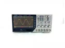
DPO6000, MPO6000 Series Digital Fluorescent Oscilloscope Product Manual V1.3
38
(10) Delay trigger
(11) Setup/Hold trigger
(12) UART trigger [optional]
(13) LIN triggering [optional]
(14) CAN trigger [optional]
(15) SPI triggering [optional]
(16) IIC trigger [optional]
Edge trigger
Edge trigger types identify triggers by looking for a specified edge (rising, falling, rising,
or falling) and voltage level on the waveform.
Rising edge Falling edge
Trigger point Trigger point
Trigger level
Press the front panel Trig Menu button to open the trigger function menu.
[Type] Select the edge and press V0 to confirm.
[Data source] Select CH1~CH4 or LA as the trigger source.
Note: LA must be inserted when LA is used as the trigger source.
[Slope] Select the required triggering edge [rising edge, falling edge, double edge], and
press V0 to confirm.
[Mode] Select the acquisition mode [Auto, Normal] and press V0 to confirm.
[50%] Set the trigger level to the vertical midpoint of the peak-to-peak value of the trig-
ger signal. The trigger level value is displayed in the upper right corner of the screen.
[Holdoff] Set the holdoff time.
Trigger level knob: The analog channel can modify the trigger level value. The trigger
mark moves up and down with the rotation of the knob. Turn the trigger level knob to
adjust the trigger level to obtain a stable trigger.
Digital channel: You can change the trigger threshold of the digital channel by setting
the threshold voltage.
Note: Pressing the Auto Scale button will set the trigger type to edge trigger and the
Loading ...
Loading ...
Loading ...