Loading ...
Loading ...
Loading ...
DPO6000, MPO6000 Series Digital Fluorescent Oscilloscope Product Manual V1.3
13
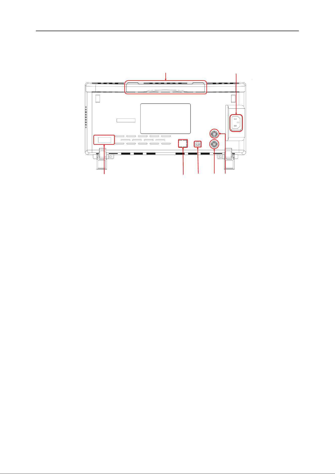
Rear panel overview
1
2
34
5
67
1. Handle
Pull the handle vertically to carry the oscilloscope conveniently. When not needed, just
press down on the handle.
2. AC power jack
AC power input. Please use the power cord provided to connect the oscilloscope to AC
power, and press the power button on the front panel to turn it on.
3. AUX port trigger output and pass / fail [optional]
Trigger output:
When the oscilloscope generates a trigger, a pulse can be output through this interface.
This pulse is the signal of the oscilloscope's current capture rate. Connect this signal to
the waveform display device and measure the frequency of the signal. The measure-
ment result is the same as the current capture rate.
Pass / Fail:
In the pass / fail test, when the oscilloscope detects a failure, it will output a pulse
through this connector. When no failure is detected, it will continuously output a low
level through this connector.
4. Signal source 3 source output [MPO6000EDU Series]
Signal source 3 output is only for the 3-channel signal source built into the oscilloscope.
When the oscilloscope signal source 3 is turned on, the signal source port outputs sig-
nals according to the current settings.
5. USB Device
This interface allows you to connect the oscilloscope to a computer or a printer. When
Loading ...
Loading ...
Loading ...