Loading ...
Loading ...
Loading ...
DPO6000, MPO6000 Series Digital Fluorescent Oscilloscope Product Manual V1.3
35
Note: "Coarse adjustment" and "Fine adjustment" can be selected not only through the
amplitude scale menu, but also by pressing the vertical voltage scale quickly.
Analog channel delay setting
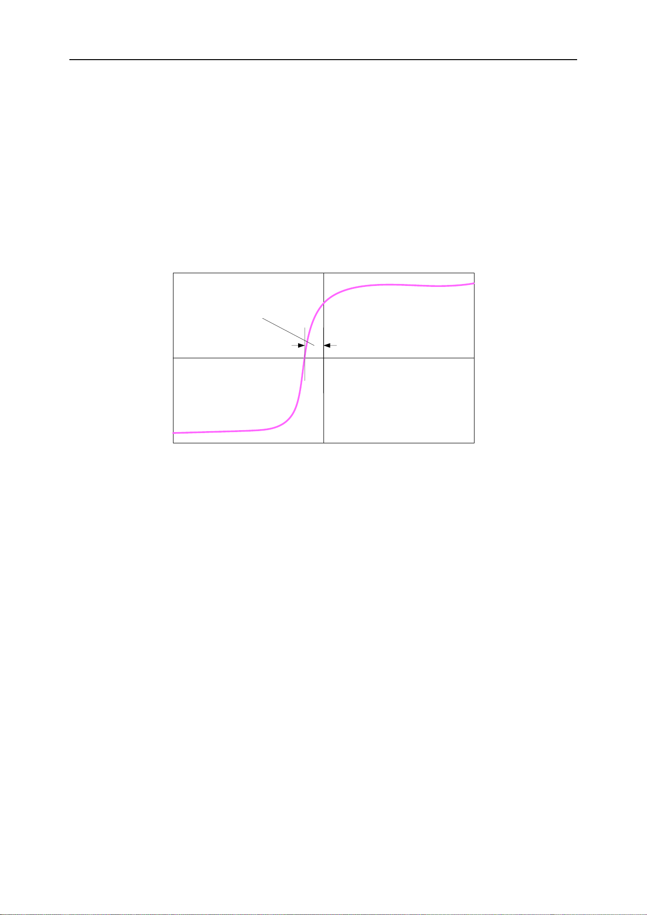
When using an oscilloscope for actual measurements, the propagation delay of the
probe cable may introduce large errors (zero drift). DPO6000 / MPO6000 series oscil-
loscopes allow users to set a delay time to correct the zero offset of the corresponding
channel. Zero offset is defined as the offset of the intersection of the waveform and the
trigger level line relative to the trigger position, as shown in the figure below.
Zero Offset
Delay correction. Turn the multi-function knob V0 to set the required delay correction
time. This parameter can be set from -100ns to 100ns. Press the multi-function knob to
restore the delay time to 0.00s.
Trigger system
Trigger can be understood as an event (or action); for example, the action of pressing
the shutter when taking a picture is a trigger, which is an event that starts the camera to
record an image. For an oscilloscope, the waveform (sampling data) will be recorded
after the trigger condition is met and displayed on the screen. When a digital oscillo-
scope is working, whether or not the instrument triggers steadily, it always acquires
waveforms continuously, but only stable triggers have a stable display. The trigger
module ensures that each time-based scan or acquisition starts from a user-defined
trigger condition, that is, each scan is synchronized with the acquisition, and the cap-
tured waveforms overlap to display a stable waveform.
The trigger setting should be based on the characteristics of the input signal, so the us-
er should have some knowledge of the signal under test in order to quickly capture the
required waveform. This oscilloscope provides a variety of trigger types, which is con-
venient for users to pay attention to the waveform details of interest.
The trigger determines when the oscilloscope starts acquiring data and displaying the
waveform. Once the trigger is set up properly, the oscilloscope can convert unstable
Loading ...
Loading ...
Loading ...