Loading ...
Loading ...
Loading ...
DPO6000, MPO6000 Series Digital Fluorescent Oscilloscope Product Manual V1.3
44
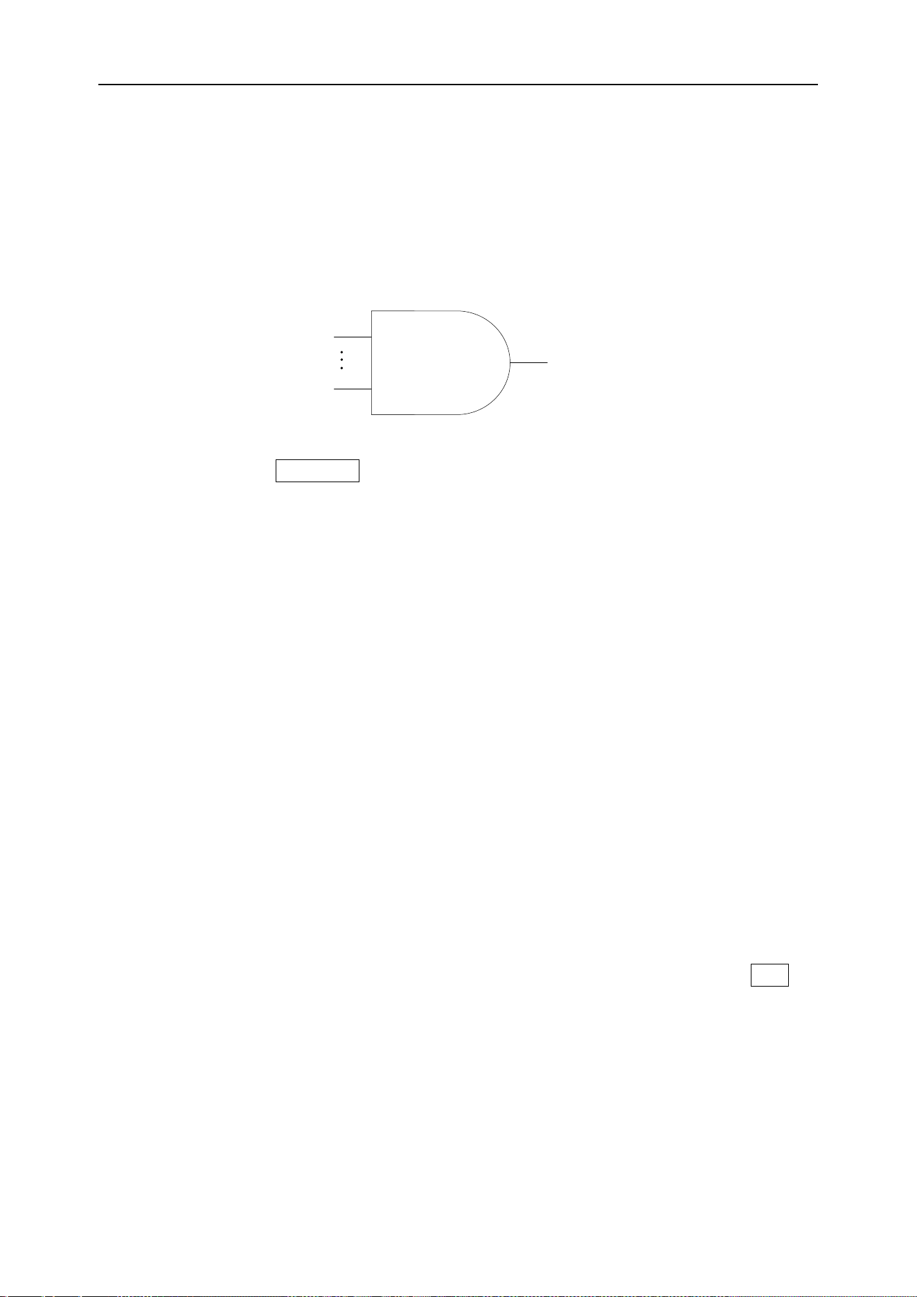
and OR combination between channels. Each channel can have a value of high (1),
low (0), or inactive (X). In the pattern trigger mode, the oscilloscope will compare the
actual pattern of the channel with the preset pattern, and trigger on the last channel
that is the same as the preset pattern (the pattern is true). If the pattern of each chan-
nel is fixed or the pattern of all channels is set to "Invalid", the oscilloscope will not trig-
ger.
CH1~CH4 & LA1~LA4
Logical value H,L,X
CH1
LA4.3
Pattern trigger output
Press the front panel Trig Menu button to open the trigger function menu.
[Type] Select the code type and press V0 to confirm.
[Data source] Select CH1~CH4 or LA as the trigger source.
Note: LA must be inserted when LA is used as the trigger source.
[Current channel pattern] Set the current channel pattern. Press V0 to confirm. The
preset pattern is displayed in the upper left corner of the screen.
1: Set the channel pattern to "H", that is, the level is higher than the trigger level of the
channel.
0: Set the channel pattern to "L", that is, the level is lower than the trigger level of the
channel.
X: Set the channel pattern to "X", that is, this channel is not used as part of the pattern.
[Mode] Select the acquisition mode (auto, normal) and press V0 to confirm.
[Holdoff] Set the holdoff time.
Trigger level knob: Press the channel button first and then move the trigger level knob
to modify the trigger level value of the corresponding channel. Trigger the mark and
move up and down with the knob. Turn the trigger level knob to adjust the trigger level
to obtain a stable trigger. For example, set the CH1 trigger level. Press soft key CH1 to
use the trigger level to modify the level.
Digital channel: You can change the trigger threshold of the digital channel by setting
the threshold voltage.
Interval trigger
Triggered when the interval between two consecutive rising edges (or falling edges)
Loading ...
Loading ...
Loading ...