Loading ...
Loading ...
Loading ...
DPO6000, MPO6000 Series Digital Fluorescent Oscilloscope Product Manual V1.3
42
[Time] Set slope time reference (8ns~10s), the slope time is the horizontal time interval
between the intersection of the high and low levels and the rising or falling edge of the
waveform.
[Mode] Select the acquisition mode [Auto, Normal] and press V0 to confirm.
[Holdoff] Set the hysteresis time.
Trigger level knob: The analog channel can modify the trigger level value. The trigger
mark moves up and down with the rotation of the knob. Turn the trigger level knob to
adjust the trigger level to obtain a stable trigger.
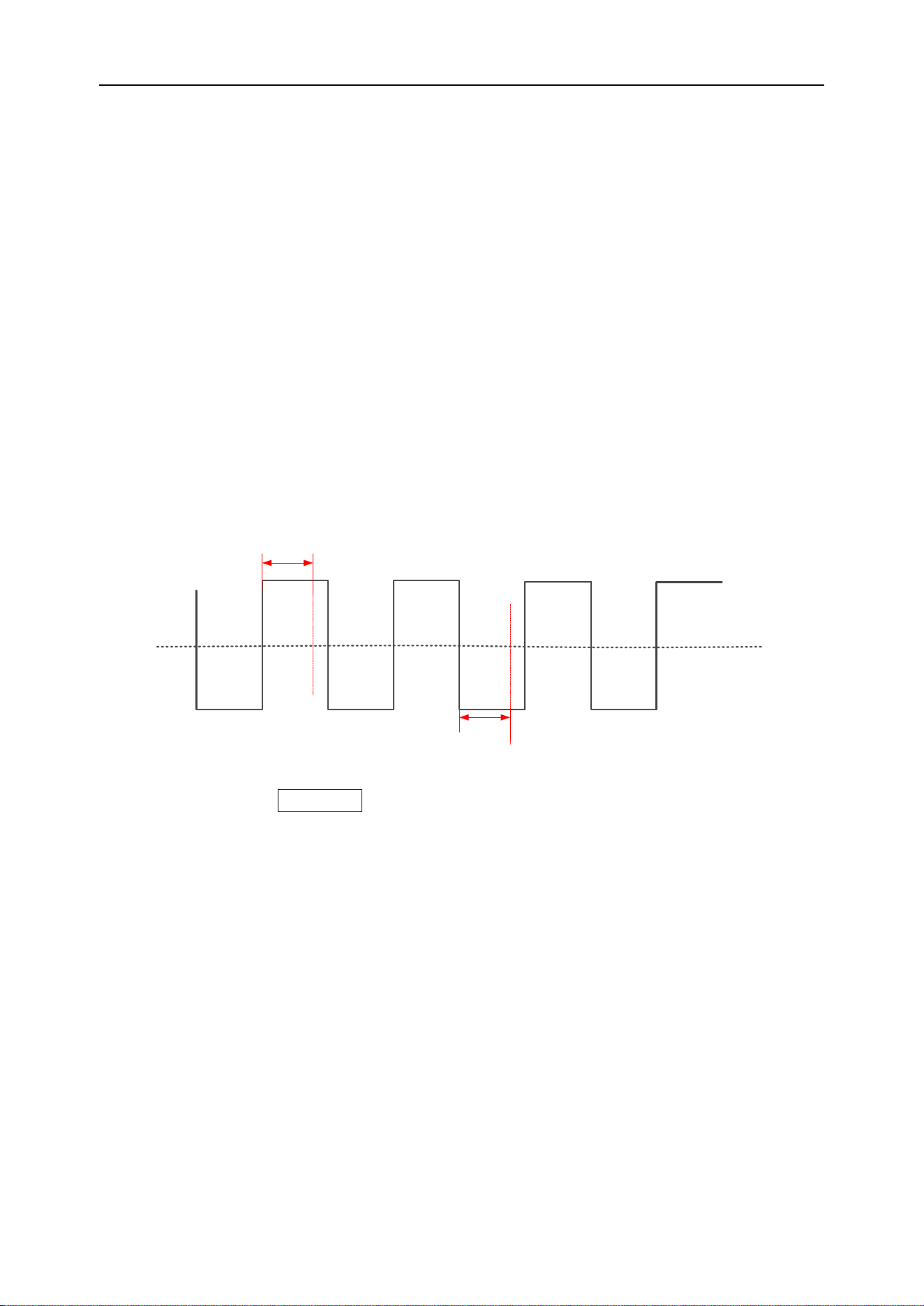
Overtime trigger
Trigger when the time interval (△T) from the rising edge (or falling edge) of the input
signal passes the trigger level to the end of the adjacent falling edge (or rising edge)
pass the trigger level is greater than the set overtime period. As shown below:
Trigger point
Trigger level
Overtime time
Overtime time
Trigger point
Press the front panel Trig Menu button to open the trigger function menu.
[Type] Select overtime and press V0 to confirm.
[Data source] Select CH1~CH4 or LA as the trigger source.
Note: LA must be inserted when LA is used as the trigger source.
[Polarity] Select the positive or negative polarity of the trigger.
[Time] Set the pulse width time (8ns~10s).
[50%] Set the trigger level to the vertical midpoint of the peak-to-peak value of the trig-
ger signal. The trigger level value is displayed in the upper right corner of the screen.
[Mode] Select the acquisition mode (auto, normal) and press V0 to confirm.
[Holdoff] Set the holdoff time.
Trigger level knob: The analog channel can modify the trigger level value. Trigger the
mark and move up and down with the knob. Turn the trigger level knob to adjust the
Loading ...
Loading ...
Loading ...