Loading ...
Loading ...
Loading ...
DPO6000, MPO6000 Series Digital Fluorescent Oscilloscope Product Manual V1.3
41
Trigger level knob: The analog channel can modify the trigger level value. The trigger
mark moves up and down with the rotation of the knob. Turn the trigger level knob to
adjust the trigger level to obtain a stable trigger.
Slope trigger
Slope trigger sets the positive or negative slope trigger of the oscilloscope from one
level to another within a specified time.
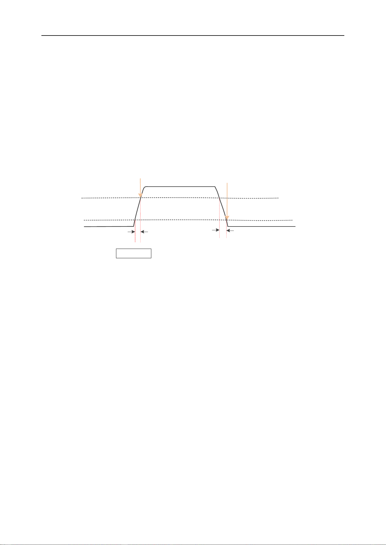
As shown in the figure below, we define the time difference between the two points
where the high and low trigger levels intersect with the rising (falling) edge of the wave-
form as the positive (negative) slope time.
Trigger point
Trigger level 1
Trigger level 2
Positive slope time
Trigger point
Negative slope time
Press the front panel Trig Menu button to open the trigger function menu.
[Type] Select the slope and press V0 to confirm.
[Data source] Select CH1~CH4 as the trigger source.
[Slope] Select the required triggering edge [rising edge or falling edge].
[Level] Select low level [V2] or high level [V1], then turn the trigger level knob to adjust
the vertical position of the high [low] level to obtain the required slope time T. The cor-
responding displacement information changes in real time and is displayed in the status
bar in the upper right corner of the screen.
[When] Set the trigger condition (>, <, =, ≠), press V0 to confirm.
> (Greater than the set time value): It can be triggered when the slope time of the ris-
ing or falling edge of the input signal is greater than the set slope time (pulse width er-
ror is 5%).
< (Smaller than the set time value): It can be triggered when the slope time of the ris-
ing or falling edge of the input signal is smaller than the set slope time (pulse width er-
ror is 5%).
= (Equal to the set time value): It can be triggered when the slope time of the rising or
falling edge of the input signal is equal to the set slope time (pulse width error is 5%).
≠(Not equal to the set time value): It can be triggered when the slope time of the rising
or falling edge of the input signal is not equal to the set slope time (pulse width error is
5%).
Loading ...
Loading ...
Loading ...