Loading ...
Loading ...
Loading ...
DPO6000, MPO6000 Series Digital Fluorescent Oscilloscope Product Manual V1.3
48
edges is equal to the set width (pulse width error is 5%).
≠ [Not equal to the set width value]: Trigger when the time difference between the set
edges is not equal to the set width (pulse width error is 5%).
[Width] Set the reference value of the time difference between the edges set by the
two data sources (8ns~10s).
[Mode] Select the acquisition mode (auto, normal) and press V0 to confirm.
[Holdoff] Set the holdoff time.
Trigger level knob: Press the channel button first and then move the trigger level knob
to modify the trigger level value of the corresponding channel. Trigger the mark and
move up and down with the knob. Turn the trigger level knob to adjust the trigger level
to obtain a stable trigger. For example, set the CH1 trigger level. Press soft key CH1 to
use the trigger level to modify the level.
Digital channel: You can change the trigger threshold of the digital channel by setting
the threshold voltage.
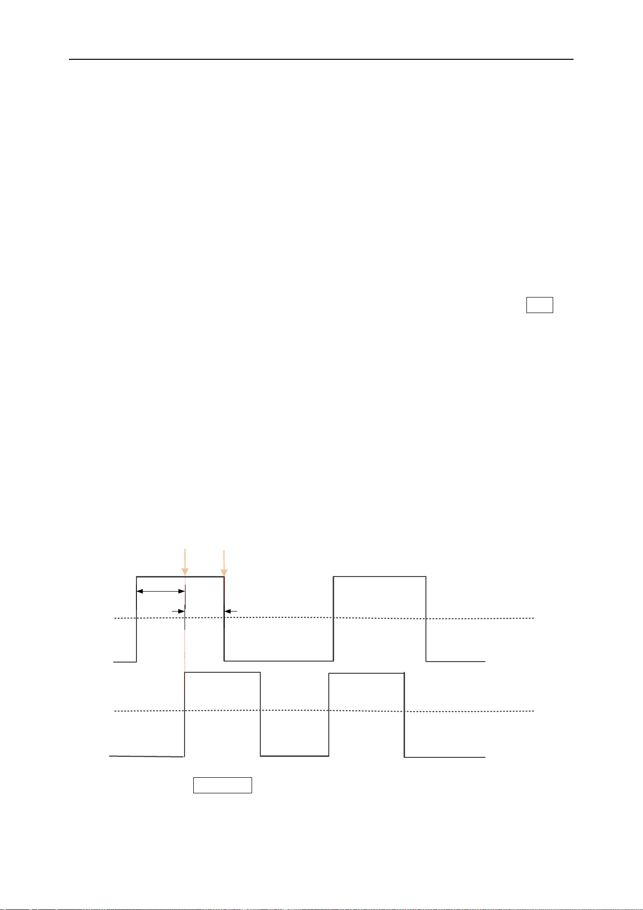
Setup/Hold trigger
Under the setup/hold trigger type, the user needs to set the data signal line and clock
signal line. The setup time starts when the data signal crosses the trigger level and
ends when the specified clock edge arrives; the hold time starts when the specified
clock edge arrives and ends when the data signal crosses the trigger level again (as
shown in the figure below). The oscilloscope will trigger when the setup time or hold
time is less than the preset time.
Data channel
Clock channel
Setup time trigger point
Hold time trigger point
Setup time
Hold time
Press the front panel Trig Menu button to open the trigger function menu.
[Type] Select Build Hold and press V0 to confirm.
Loading ...
Loading ...
Loading ...