Loading ...
Loading ...
Loading ...

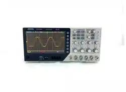
DPO6000, MPO6000 Series Digital Fluorescent Oscilloscope Product Manual V1.3
50
Note: LA must be inserted when LA is used as the trigger source.
[Baud rate] Select the baud rate.
DPO6000 / MPO6000 series machines provide users with common baud rates as fol-
lows:
110
300
600
1200
2400
4800
9600
14400
19200
38400
57600
115200
230400
380400
460400
Custom
If the user finds the required baud rate in the table above, you can select Custom and
set your own baud rate.
[Custom] Users set their own baud rate {only available if you choose to customize this
menu}
[When] Set UART trigger conditions:
Start bit: When the UART start bit appears, trigger in the middle of the bit.
Stop bit: When the UART stop bit appears, it triggers in the middle of the bit. Regard-
less of the stop position 1, 1.5, 2 of the device under test, the machine will process it
according to 1 bit.
Data: The normal reception of data is completed, and the received UART data and us-
er-set data are equal to trigger at the stop bit.
Parity error: The normal reception of data is completed. When a parity error occurs in
the data, it is triggered at the stop bit.
Data bit error: When the data is checked at the stop bit of the start bit, it is triggered
when an error occurs.
[Idle level] The level value (level / high level) when the UART is idle. The default set-
ting is high level.
[Parity check] Set whether the measured UART data is checked (odd check, even
check or none).
[Data bits] Set the length of the UART data to be measured (5, 6, 7, 8 bits can be se-
lected).
[Data] The trigger data set by the user (only available when the trigger type is data).
[Mode] Select the acquisition mode (auto, normal) and press V0 to confirm.
[Holdoff] Set the holdoff time.
Loading ...
Loading ...
Loading ...