Loading ...
Loading ...
Loading ...

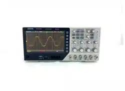
DPO6000, MPO6000 Series Digital Fluorescent Oscilloscope Product Manual V1.3
49
[Data] Select CH1~CH4 or LA as the trigger source.
Note: LA must be inserted when LA is used as the trigger source.
[Data type] Select high level or low level.
[Clock] Select CH1~CH4 or LA as the trigger source of the clock channel.
Note: LA must be inserted when LA is used as the trigger source.
[Slope] Select the required triggering edge (rising edge or falling edge).
[Polarity] Select the hold type (establish or hold).
Setup: The time when the data is stable before the clock edge arrives.
Hold: The time when the data is stable after the clock edge arrives.
[Width] Set the setup time and hold time separately.
[Mode] Select the acquisition mode (auto, normal) and press V0 to confirm.
[Holdoff] Set the holdoff time.
Trigger level knob: Press the channel button first and then move the trigger level knob
to modify the trigger level value of the corresponding channel. Trigger the mark and
move up and down with the knob. Turn the trigger level knob to adjust the trigger level
to obtain a stable trigger. For example, set the CH1 trigger level. Press soft key CH1 to
use the trigger level to modify the level.
Digital channel: You can change the trigger threshold of the digital channel by setting
the threshold voltage.
UART trigger [optional]
UART bus is a serial communication method used for data transfer between computers
or between computers and terminals. The UART serial protocol transmits a character
as a frame of data, and its frame structure is composed of a 1-bit start bit, 5-8 bits data
bit, 1-bit check bit, and 1--2 bit stop bit.
Free bit
1/0 1/0 ... 1/0
Check
bit
Start bit
Data bit:5~8bits
Stop bit:1~2bits
Check bit:0~1bit
Its format is shown above. DPO6000 / MPO6000 series oscilloscope can trigger when it
detects the frame start, stop bit, data, parity error or data bit error of the UART signal.
Press the Trig Menu button on the front panel to enter the trigger function menu.
[Type] Select UART and press V0 to confirm.
[Data source] Select CH1~CH4 or LA as the trigger source.
Loading ...
Loading ...
Loading ...
