Loading ...
Loading ...
Loading ...
DGS-3130 Series Layer 3 Stackable Managed Switch Web UI Reference Guide
383
Parameter Description
Alarm Time Enter the time period used to define the time from when a defect is detected on
the MEP to when a fault alarm will be sent. The range is from 250 to 1000
centiseconds. By default, this value is 250 centiseconds.
Alarm Reset Time
Enter the time period used to define the time from when all defects detected on
the MEP are removed to when the fault alarm mechanism will be reset. The
range is from 250 to 1000 centiseconds. By default, this value is 1000
centiseconds.
AIS State Select the enable or disable the AIS feature on this interface here.
AIS Period
Select the transmitting interval of the AIS PDU here. Options to choose from
are 1 Second and 1 Minute. The default period is 1 second.
AIS Client Level Select the client level ID to which the MEP sends the AIS PDUs here. The
default client MD level is that the most immediate client layer Maintenance
domain Intermediate Points (MIP) and MEPs exist on. The range is from 0 to 7.
LCK State Select the enable or disable the LCK feature on this interface here.
LCK Period Select the transmitting interval of the LCK PDU here. Options to choose from
are 1 Second and 1 Minute. The default period is 1 second.
LCK Client Level Select the client level ID to which the MEP sends the LCK PDU here. The
default client MD level is the MD level that the most immediate client layer MIPs
and MEPs exist on. The range is from 0 to 7.
Click the Apply button to accept the changes made.
Click the Back button to return to the previous window.
After clicking the Remote MEP button, the following page will appear.
Figure 10-8 CFM Settings (Add MA, Add MEP, Remote MEP) Window
Click the Back button to return to the previous window.
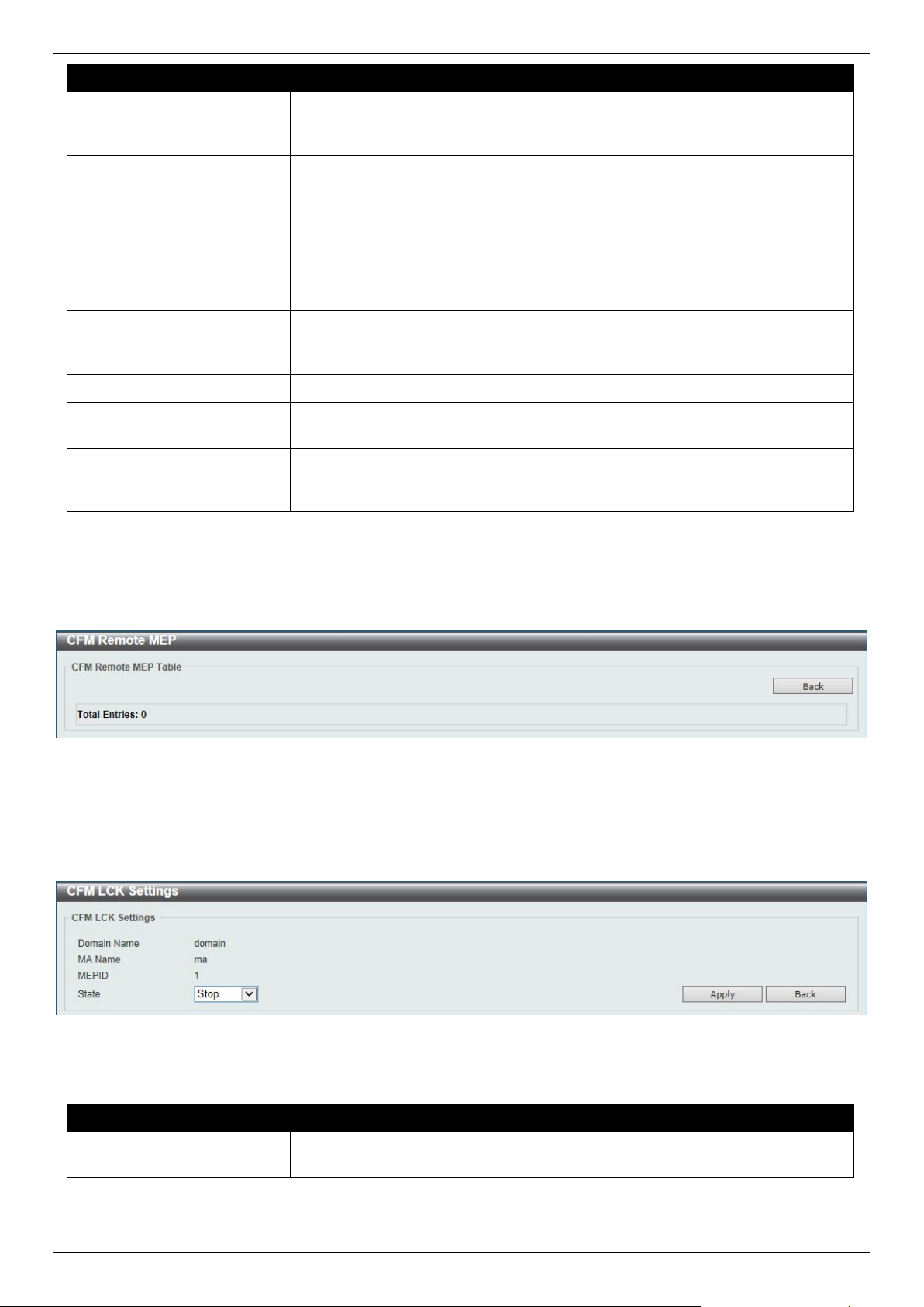
After clicking the Edit LCK button, the following page will appear.
Figure 10-9 CFM Settings (Add MA, Add MEP, Edit LCK) Window
The fields that can be configured are described below:
Parameter Description
State
Select to Start or Stop the administrative lock action here. This feature will
result in the MEP to send LCK PDUs to a client level MEP.
Click the Apply button to accept the changes made.
Click the Back button to return to the previous window.
Loading ...
Loading ...
Loading ...