
Loading ...
Loading ...
Loading ...
ELECTRICAL SYSTEM 16-71
Meter, Gauge, Indicator Unit
NOTICE
Do not drop the meter unit. Place the meter unit so
that it faces upward. If the meter assembly is left up-
side down or sideways for a long time or dropped,
it will malfunction. Do not short each terminals.
Liquid Crystal Display (LCD) Segments Check
•
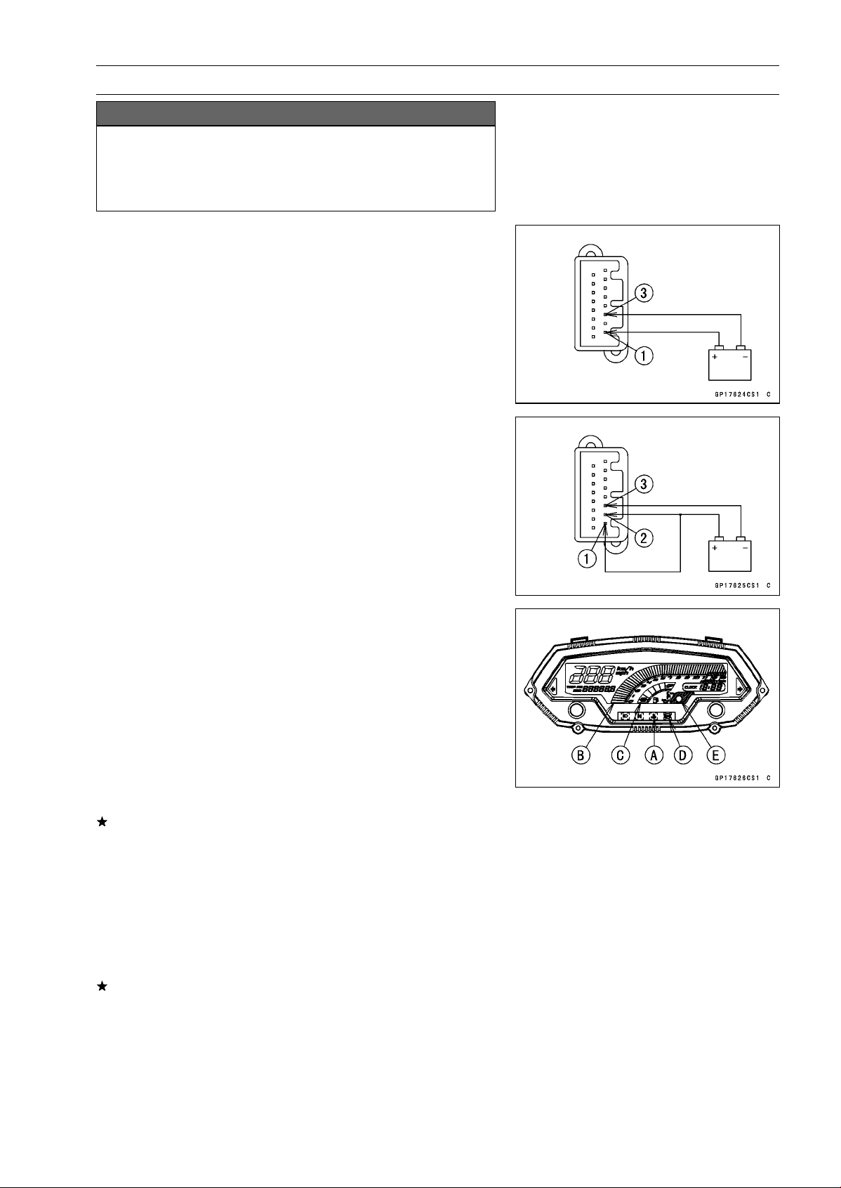
Using the insulated auxiliary leads, connect the 12 V bat-
tery to the meter unit connector as follows.
○
Connect the battery positive terminal to the terminal [1].
○
Connect the battery negative terminal to the terminal [3].
•
Connect the terminal [2] to the terminal [1].
•
When the terminals are connected, the meter unit dis-
plays the following.
○
The water temperature warning indicator light (LED) [A]
goes on for 2 seconds.
○
The tachometer [B] and the fuel level gauge [C] momen-
tarily goes from the minimum to the maximum, then goes
back from the maximum to the minimum reading.
○
The speedometer and the odometer segments appear
from left, then disappear from left.
○
After the above indicaiton, all the LCD segments appear
for about 0.5 second.
If the LCD segments do not appear, replace the meter
assembly.
○
For models equipped with an ABS, the ABS indicator light
(LED) [D] goes on.
•
Disconnect the terminal [2].
○
All the LCD segments disappear.
○
For models equipped with an immobilizer system, the
warning indicator light (LED) [E] starts flashing (see
A
bstract section in the Immobilizer System).
If the segments do not disappear, replace the meter as-
sembly.
Loading ...
Loading ...
Loading ...