
Loading ...
Loading ...
Loading ...
3-64 FUEL SYSTEM (DFI)
Speed Sensor (Service Code 24, 25)
Speed Sensor Removal/Installation
•
Refer to the Speed Sensor Removal/Installation in the
Electrical System chapter.
Speed Sensor Input Voltage Inspection
NOTE
○
Be sure the battery is fully charged.
•
Turn the ignition switch OFF.
•
Disconnect the speed sensor connector and connect the
harness adapter [A] between these connectors.
Special Tool - Speed Sensor Measuring Adapter: 57001
-1400
•
Connect a digital meter to the harness adapter leads.
Speed Sensor Input Voltage
Connections to Adapter:
Digital Meter (+) BL (sensor P) lead
Digital Meter (–) BK/BL (sensor BK) lead
•
Measure the input voltage with the engine stopped and
with the connector joined.
•
Turn the ignition switch ON.
Input Voltage
Standard: About DC 9
∼ 11 V
•
Turn the ignition switch OFF.
If the reading is within the standard, check the output volt-
age (see Speed Sensor Output Voltage Inspection).
If the reading is out of the standard, remove the ECU
and check the wiring for continuity between main harness
connectors.
○
Disconnect the ECU and sensor connectors.
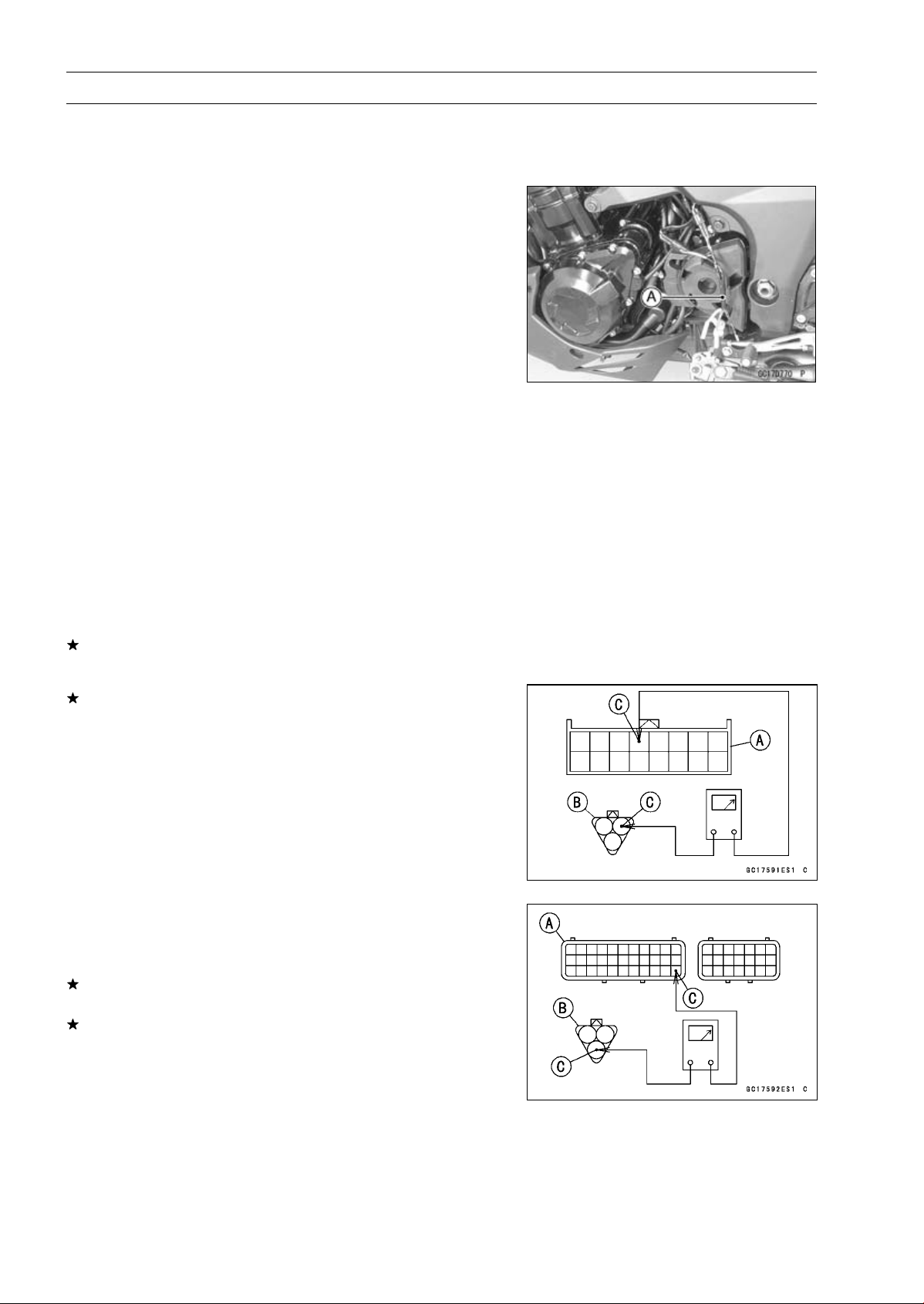
Wiring Inspection
Speed Meter Connector [A]
Speed Sensor Connector [B]
BL lead [C]
Speed Meter Connector [A]
Speed Sensor Connector [B]
BR/BK lead (ECU terminal 33) [C]
If the wiring is good, check the ECU for its ground and
power supply (see ECU Power Supply Inspection).
If the ground and power supply are good, replace the ECU
(see ECU Removal/Installation).
Loading ...
Loading ...
Loading ...