
Loading ...
Loading ...
Loading ...
12-36 BRAKES
Anti-Lock Brake System (Equipped Models)
Even when the ABS is operating normally, the ABS indi-
cator light (LED) may light up under the conditions listed be-
low. Turn the ignition switch OFF to stop the indicator light.
If the motorcycle runs without erasing the service code, the
light may light up again.
○
After continuous riding on a rough road.
○
When the engine is started with the stand raised and the
transmission engaged, and the rear wheel turns.
○
When accelerating so abruptly that the front wheel leaves
the ground.
○
When the ABS has been subjected to strong electrical
interference.
○
When tire pressure is abnormal. Adjust tire pressure.
○
When a tire different in size from the standard size is being
used. Replace with standard size.
○
When the wheel is deformed. Replace the wheel.
Much of the ABS troubleshooting work consists of con-
firming continuity of the wiring. The ABS parts are assem-
bled and adjusted by the manufacturer, so there is no need
to disassemble or repair them. Replace the ABS hydraulic
unit.
The basic troubleshooting procedures are listed below.
•
Carry out pre-diagnosis inspections as a preliminary in-
spection.
•
Determine the fault using the self-diagnosis function.
•
Check wiring and connections from the ABS hydraulic
unit connector to the suspected faulty ABS part, using the
hand tester.
Special Tool - Hand Tester: 57001-1394
•
Visually inspect the wiring for signs of burning or fraying.
If any wiring is poor, replace the damaged wiring.
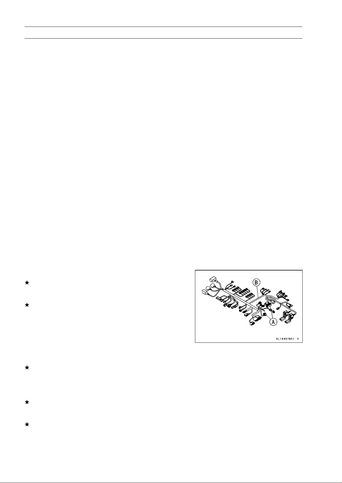
•
Pull each connector [A] apart and inspect it for corrosion,
dirt and damage.
If the connector is corroded or dirty, clean it carefully. If it
is damaged, replace it.
•
Check the wiring for continuity.
○
Use the wiring diagram to find the ends of the lead which
is suspected of being a problem.
○
Connect the hand tester between the ends of the leads.
Special Tool - Hand Tester: 57001-1394
○
Set the tester to the × 1 Ω range, and read the tester.
If the tester does not read 0 Ω, the lead is defective. Re-
place the main harness [B] if necessary.
•
Narrow down suspicious parts and close in on the faulty
ABS part by repeating the continuity tests.
If no abnormality is found in the wiring or connectors, the
ABS parts are the next likely suspects. Check each part
one by one.
If an abnormality is found, replace the affected ABS part.
Loading ...
Loading ...
Loading ...