
Loading ...
Loading ...
Loading ...
FUEL SYSTEM (DFI) 3-65
Speed Sensor (Service Code 24, 25)
Speed Sensor Output Voltage Inspection
•
Using the stand, raise the rear wheel off the ground.
•
Measure the output voltage at the speed sensor in the
same way as input voltage inspection, note the following.
○
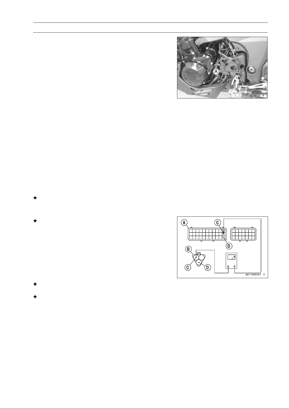
Disconnect the speed sensor connector and connect the
harness adapter [A] between these connectors.
Special Tool - Speed Sensor Measuring Adapter: 57001
-1400
Speed Sensor Output Voltage
Connections to Adapter:
Digital Meter (+) Y/W (sensor Y) lead
Digital Meter (–) BK/BL (sensor BK) lead
•
Measure the output voltage with the engine stopped and
with the connector joined.
•
Turn the ignition switch ON.
Output Voltage
Standard: Less than DC 0.6 V or over than 4.8 V at
ignition switch ON and 0 km/h
NOTE
○
Rotate the rear wheel by hand, confirm the output volt-
age will be raise or lower.
•
Turn the ignition switch OFF.
If the reading is out of the standard, check the speed sen-
sor (see Speed Sensor Inspection in the Electrical System
chapter).
If the reading is within the standard, remove the ECU and
check the wiring for continuity between main harness con-
nectors.
○
Disconnect the ECU and sensor connectors.
Wiring Inspection
ECU Connector [A]
Speed Sensor Connector [B]
P lead (ECU terminal 22) [C]
BR/BK lead (ECU terminal 33) [D]
If the wiring is good, check the ECU for its ground and
power supply (see ECU Power Supply Inspection).
If the ground and power supply are good, replace the ECU
(see ECU Removal/Installation).
Loading ...
Loading ...
Loading ...