Loading ...
Loading ...
Loading ...
Note
Make sure no persons are in the lane when powering on the
device.
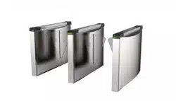
5.3 Switch to RS-485/RS-232 Mode
Take the Serial Port 4 and on the access control board as an
example. If the Jumper cap's posion is like the picture displayed
below. (The black part is the jumper cap.) The serial port is in
RS-485
communicaon mode.
Figure 5-2 Jumper Cap Status of RS-485 Interface
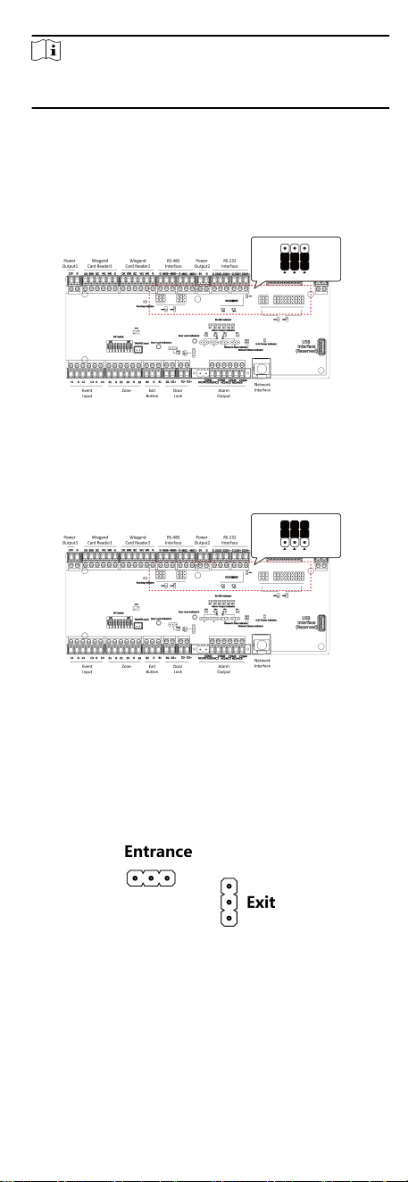
If the Jumper cap's posion is like the picture displayed below.
(The black part is the jumper cap.) The serial port is in RS-232
communicaon mode.
Figure 5-3 Jumper Cap Status of RS-232 Interface
5.4 Switch Relay Output Mode (NO/NC)
5.4.1 Barrier Control Relay Output Mode
The pins of the barrier control relay on the access control board is
as below:
Figure 5-4 Pin Appearance
The jumper cap's posion of barrier opening for entrance (NO) is
as below:
25
Loading ...
Loading ...
Loading ...