
Loading ...
Loading ...
Loading ...
●
Warning tags can be viewed on the side panel of each pedestal.
●
Safety Instrucons can be viewed on the middle panel inside
the pedestal.
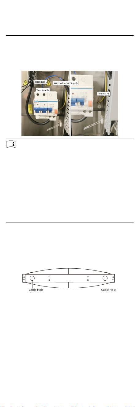
4.2 Wiring Electric Supply
Wire electric supply with the switch in the pedestal. Terminal L
and terminal N are on the switch, while terminal PE should
connect to a ground wire (yellow and green wire).
Note
●
The cable bare part should be no more than 8 mm. It is
suggested that you can immerse the bare part into the liquid
n. If possible, wear an insulaon cap at the end of the bare
cable. Make sure there’s no bare copper or cable aer the
wiring.
●
The Terminal L and the Terminal N cannot be wired reversely.
Do not wire the input and output terminal reversely.
●
To avoid people injury and device damage, when tesng, the
ground resistance of the
equipotenal points should not be
larger than 2 Ω。
●
Use the device in
conjuncon with an UPS.
4.3 Wire Interconnecng Cable
You should use interconnecng cables to connect the main lane
board and the sub lane board for components communicaon.
The picture displayed below describes the cable hole's posion
on the pedestals.
Figure 4-3 Cable Hole of Interconnecng Cable
Follow the instrucons below to connect the interconnecng
cable.
9
Loading ...
Loading ...
Loading ...