Loading ...
Loading ...
Loading ...
mode, pair the keyfob, inialize the hardware, switching between
RS-485 communicaon mode and RS-232 communicaon mode,
and view relay output NO/NC diagram by seng the DIP switch
on the access control board.
●
Normal Mode: The device will work properly.
●
Test Mode: Test mode is the same as the normal mode except
that the device cannot report the alarm, the event, or the
people
counng informaon to the center.
●
Passing Mode: There are 9 passing modes, including controlled
bi-direcon, controlled entrance and prohibited exit, controlled
entrance and free exit, free
bi-direcon, free entrance and
controlled exit, free entrance and prohibited exit, prohibited bi-
direcon, prohibited entrance and free exit.
●
Memory Mode: By default, the memory mode is enabled.
When mulple cards are presented and authencated, it
allows
mulple persons passing through the lane. When it
counts the passing people number is equal to the card
presented mes, or no person passing through the lane aer
the last person passing, the barriers will be closed.
Note
You can also set the DIP switch on the access control board to
control the entrance and exit controlling type, keyfob pairing, etc.
For details about the DIP switch value, see DIP Switch.
5.1 Pair Keyfob (Oponal)
Pair the remote control to the device through DIP switch to open/
close the barrier remotely.
Before You Start
Ask our technique supports or sales and purchase the keyfob.
Steps
Note
Up to 32 keyfobs can be added to the turnsle.
1. Power o the turnsle.
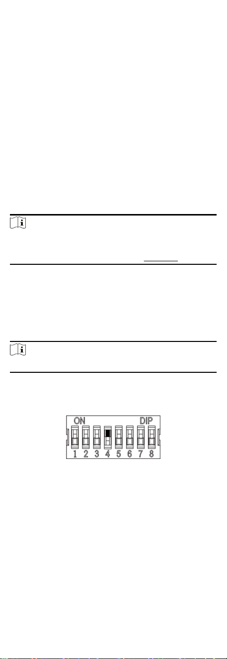
2. Set the No.4 switch of the DIP Switch on the access control
board to the ON side.
3. Power on the turnsle and it will enter the keyfob pairing
mode.
4. Hold the Close
buon for more than 10 seconds. Or pair
turnsle and keyfob in the client soware, see Manage Keyfob
User of the user manual for more details.
The keyfob's indicator of the will
ash twice if the pairing is
completed.
5. Set the No.4 switch to OFF, and reboot the turnsle to take
eect.
23
Loading ...
Loading ...
Loading ...