Loading ...
Loading ...
Loading ...
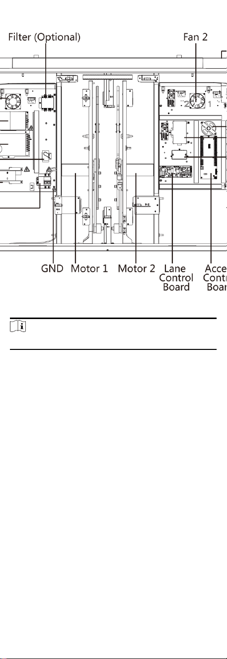
Figure 4-1 Components Diagram 1
Note
For details about wiring arrangement, refers to the actual device.
The picture displayed below describes the IR adapter and the IR
sending/receiving module and their corresponding number on
the pedestal.
7
Loading ...
Loading ...
Loading ...