Loading ...
Loading ...
Loading ...
System will cancel the passing permission if a person does not
pass through the lane within the valid passing duraon
●
Opens/closes barrier according to the schedule template
●
Up to 3000 visitor cards and up to 60,000 non-visitor cards can
be added
●
Up to 180,000 presenng card events can be recorded
●
Adjustable indicator light brightness
2 System Wiring
The
preparaon before installaon and general wiring.
Steps
1. Draw a central line on the installaon surface of the le or
right pedestal.
2. Draw other parallel lines for installing the other pedestals.
Note
The distance between the nearest two line is L+300 mm. L
represents the lane width.
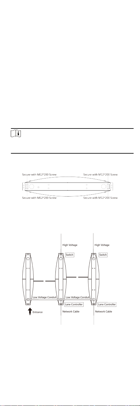
3. Slot on the installaon surface and dig installaon holes
according to the hole posion diagram.
Figure 2-1 Hole
Posion Diagram
4. Bury cables. Each lane buries 1 network cable and 1 high
voltage cable. For details, see the system wiring diagram below.
Figure 2-2 System Wiring Diagram (General Wiring)
2
Loading ...
Loading ...
Loading ...