
Loading ...
Loading ...
Loading ...
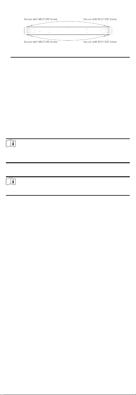
Figure 3-4 Installaon Footprint
6. Remove the auxiliary scks at the boom of the device aer
the device is fully installed. And then use the concrete to seal
the holes.
4 General Wiring
4.1 Components Introducon
By default, basic components of the turnsle are connected well.
The pedestals can communicate by wiring the
interconnecng
cables. And the turnsle supports wiring the AC electric supply
for the whole system's power supply.
Note
The voltage uctuaon of the electric supply is between 100 VAC
and 220 VAC, 50 to 60 Hz.
The picture displayed below describes each component's posion
on the turnsle.
Note
The diagram is for reference only.
6
Loading ...
Loading ...
Loading ...