
Loading ...
Loading ...
Loading ...
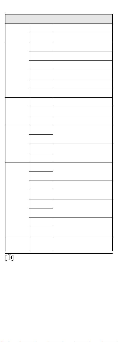
Access Control Board Terminal Descripon
Power
Input
+24 V 24 VDC Power Input
GND Grounding
Event
Input
C1 Event Alarm Input 4
GND Grounding
C2 Fire Input
C3 Event Alarm Input 2
GND Grounding
C4 Event Alarm Input 1
Exit
Buon
B2 Door 2 Signal Input
GND Grounding
B1 Door 1 Signal Input
Door Lock
(Relay)
D1-
Door 1 Relay Output (Dry
Contact)
D1+
D2-
Door 2 Relay Output (Dry
Contact)
D2+
Alarm
Output
NO/NC1
Alarm Output Relay 1 (Dry
Contact)
COM1
NO/NC2
Alarm Output Relay 2 (Dry
Contact)
COM2
NO/NC3
Alarm Output Relay 3 (Dry
Contact)
COM3
NO/NC4
Alarm Output Relay 4 (Dry
Contact)
COM4
Network
Interface
LAN Network Accessing
Note
●
The alarm input hardware interface is normally open by
default. So only the normally open signal is allowed. It can be
linked to the buzzer of the card reader and access controller,
and the alarm relay output and open door relay output.
●
The DIP of RS-485 card ID is set as 1 and 4 by default. 1 is for
entering, and 4 is for exing. If the user has congured visitor
card, you should connect two card readers on the exing side.
15
Loading ...
Loading ...
Loading ...