Loading ...
Loading ...
Loading ...
EC-692
[QR (WITHOUT EURO-OBD)]
DTC P0327, P0328 KS
Specification data are reference values and are measured between each terminal and ground.
CAUTION:
Do not use ECM ground terminals when measuring input/output voltage. Doing so may result in dam-
age to the ECM's transistor. Use a ground other than ECM terminals, such as the ground.
Diagnostic Procedure BBS001ON
1. CHECK KNOCK SENSOR INPUT SIGNAL CIRCUIT-I
1. Turn ignition switch OFF.
2. Disconnect ECM harness connector.
3. Check resistance between ECM terminal 15 and ground. Refer to Wiring Diagram.
NOTE:
It is necessary to use an ohmmeter which can measure more than 10 MΩ.
4. Also check harness for short to ground and short to power.
OK or NG
OK >> GO TO 4.
NG >> GO TO 2.
2. CHECK KNOCK SENSOR INPUT SIGNAL CIRCUIT-II
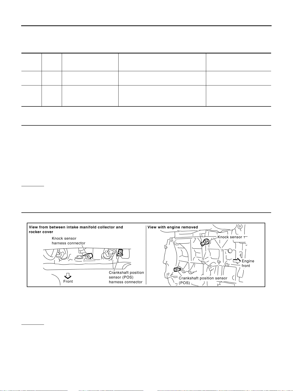
1. Disconnect knock sensor harness connector.
2. Check harness continuity between knock sensor terminal 1 and ECM terminal 15.
Refer to Wiring Diagram.
3. Also check harness for short to ground and short to power.
OK or NG
OK >> GO TO 3.
NG >> Repair open circuit or short to ground or short to power in harness or connectors.
TERMI-
NAL
NO.
WIRE
COLOR
ITEM CONDITION DATA (DC Voltage)
15 W Knock sensor
[Engine is running]
● Idle speed
Approximately 2.5V
54 —
Sensor ground
(Knock sensor)
[Engine is running]
● Warm-up condition
● Idle speed
Approximately 0V
Resistance: Approximately 530 - 590kΩ [at 20°C (68°F)]
Continuity should exist.
PBIB0512E
Loading ...
Loading ...
Loading ...