Loading ...
Loading ...
Loading ...
EC-250
[QR (WITH EURO-OBD)]
DTC P0327, P0328 KS
Specification data are reference values and are measured between each terminal and ground.
CAUTION:
Do not use ECM ground terminals when measuring input/output voltage. Doing so may result in dam-
age to the ECM's transistor. Use a ground other than ECM terminals, such as the ground.
Diagnostic Procedure BBS001DR
1. CHECK KNOCK SENSOR INPUT SIGNAL CIRCUIT-I
1. Turn ignition switch OFF.
2. Disconnect ECM harness connector.
3. Check resistance between ECM terminal 15 and ground. Refer to Wiring Diagram.
NOTE:
It is necessary to use an ohmmeter which can measure more than 10 MΩ.
4. Also check harness for short to ground and short to power.
OK or NG
OK >> GO TO 4.
NG >> GO TO 2.
2. CHECK KNOCK SENSOR INPUT SIGNAL CIRCUIT-II
1. Disconnect knock sensor harness connector.
2. Check harness continuity between ECM terminal 15 and knock sensor terminal 1.
Refer to Wiring Diagram.
3. Also check harness for short to ground and short to power.
OK or NG
OK >> GO TO 3.
NG >> Repair open circuit or short to ground or short to power in harness or connectors.
TERMI-
NAL
NO.
WIRE
COLOR
ITEM CONDITION DATA (DC Voltage)
15 W Knock sensor
[Engine is running]
● Idle speed
Approximately 2.5V
54 —
Sensor ground
(Knock sensor)
[Engine is running]
● Warm-up condition
● Idle speed
Approximately 0V
Resistance: Approximately 530 - 590kΩ [at 20°C (68°F)]
Continuity should exist.
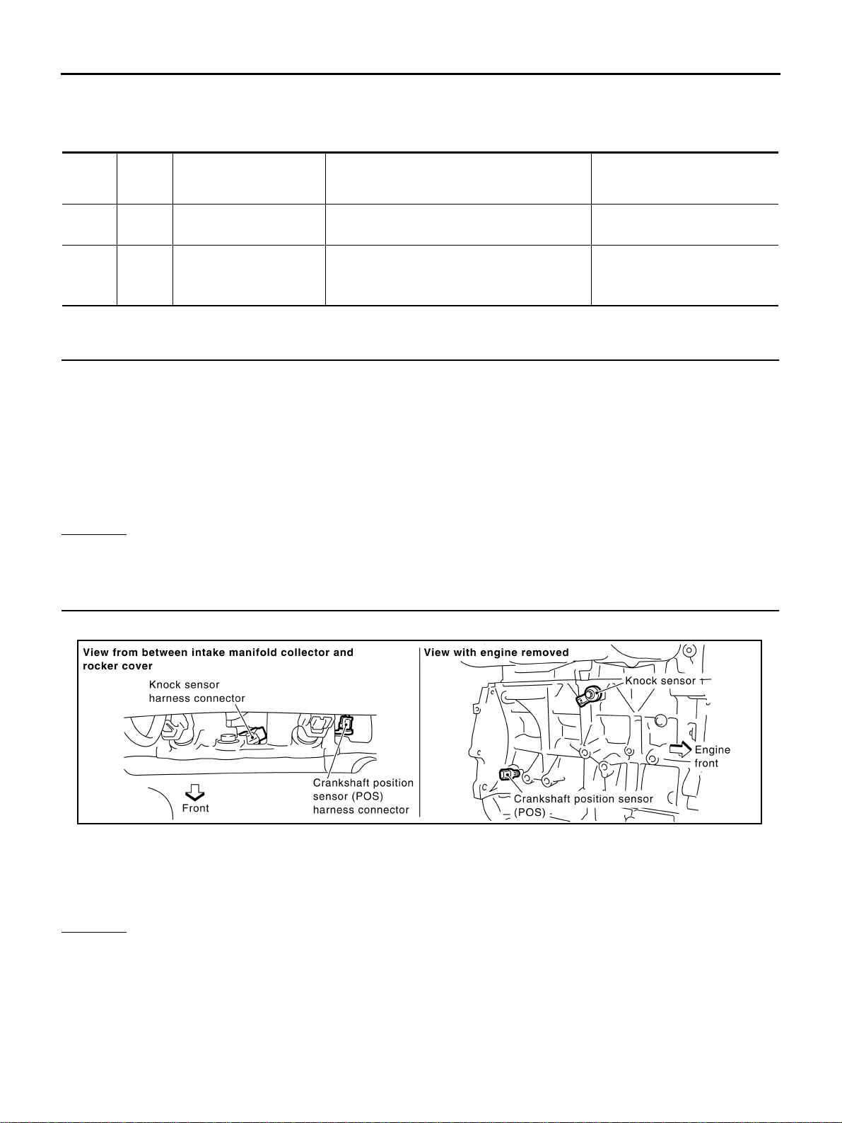
PBIB0512E
Loading ...
Loading ...
Loading ...