Loading ...
Loading ...
Loading ...
TROUBLE DIAGNOSIS
EC-115
[QR (WITH EURO-OBD)]
C
D
E
F
G
H
I
J
K
L
M
A
EC
SRT WORK SUPPORT Mode
This mode enables a technician to drive a vehicle to set the SRT while monitoring the SRT status.
DTC WORK SUPPORT Mode
REAL TIME DIAGNOSIS IN DATA MONITOR MODE (RECORDING VEHICLE DATA)
Description
CONSULT-II has two kinds of triggers and they can be selected by touching “SETTING” in “DATA MONITOR”
mode.
1. “AUTO TRIG” (Automatic trigger):
● The malfunction will be identified on the CONSULT-II screen
in real time.
In other words, DTC/1st trip DTC and malfunction item will be
displayed if the malfunction is detected by ECM.
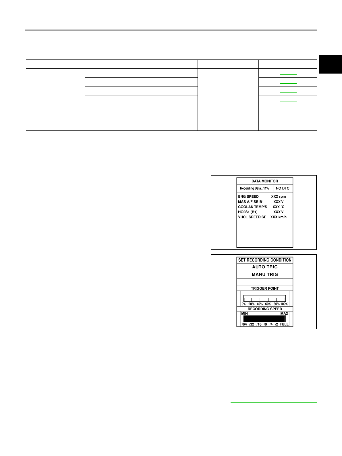
At the moment a malfunction is detected by ECM, “MONI-
TOR” in “DATA MONITOR” screen is changed to “Recording
Data ... xx%” as shown at right, and the data after the mal-
function detection is recorded. Then when the percentage
reached 100%, “REAL-TIME DIAG” screen is displayed. If
“STOP” is touched on the screen during “Recording Data ...
xx%”, “REAL-TIME DIAG” screen is also displayed.
The recording time after the malfunction detection and the
recording speed can be changed by “TRIGGER POINT” and
“Recording Speed”. Refer to CONSULT-II Operation Manual.
2. “MANU TRIG” (Manual trigger):
● DTC/1st trip DTC and malfunction item will not be displayed
automatically on CONSULT-II screen even though a malfunc-
tion is detected by ECM.
DATA MONITOR can be performed continuously even though
a malfunction is detected.
Operation
1. “AUTO TRIG”
● While trying to detect the DTC/1st trip DTC by performing the DTC Confirmation Procedure, be sure to
select to “DATA MONITOR (AUTO TRIG)” mode. You can confirm the malfunction at the moment it is
detected.
● While narrowing down the possible causes, CONSULT-II should be set in “DATA MONITOR (AUTO
TRIG)” mode, especially in case the incident is intermittent.
When you are inspecting the circuit by gently shaking (or twisting) the suspicious connectors, compo-
nents and harness in the “DTC Confirmation Procedure”, the moment a malfunction is found the DTC/
1st trip DTC will be displayed. (Refer to “Incident Simulation Tests” in GI-23, "
How to Perform Efficient
Diagnosis for an Electrical Incident" .)
2. “MANU TRIG”
Test mode Test item Condition Reference page
HO2S1
HO2S1 (B1) P0133
Refer to corresponding
trouble diagnosis for
DTC.
EC-189
HO2S1 (B1) P0134 EC-199
HO2S1 (B1) P1143 EC-325
HO2S1 (B1) P1144 EC-331
H02S2
HO2S2 (B1) P0139 EC-214
HO2S2 (B1) P1146 EC-337
HO2S2 (B1) P1147 EC-345
SEF705Y
SEF707X
Loading ...
Loading ...
Loading ...