Loading ...
Loading ...
Loading ...
DTC P0135 A/F SENSOR 1 HEATER
EC-1137
[YD (WITH EURO-OBD)]
C
D
E
F
G
H
I
J
K
L
M
A
EC
Specification data are reference values and are measured between each terminal and ground.
Pulse signal is measured by CONSULT-II.
CAUTION:
Do not use ECM ground terminals when measuring input/output voltage. Doing so may result in dam-
age to the ECM's transistor. Use a ground other than ECM terminals, such as the ground.
: Average voltage for pulse signal (Actual pulse signal can be confirmed by oscilloscope.)
Diagnostic Procedure BBS002JU
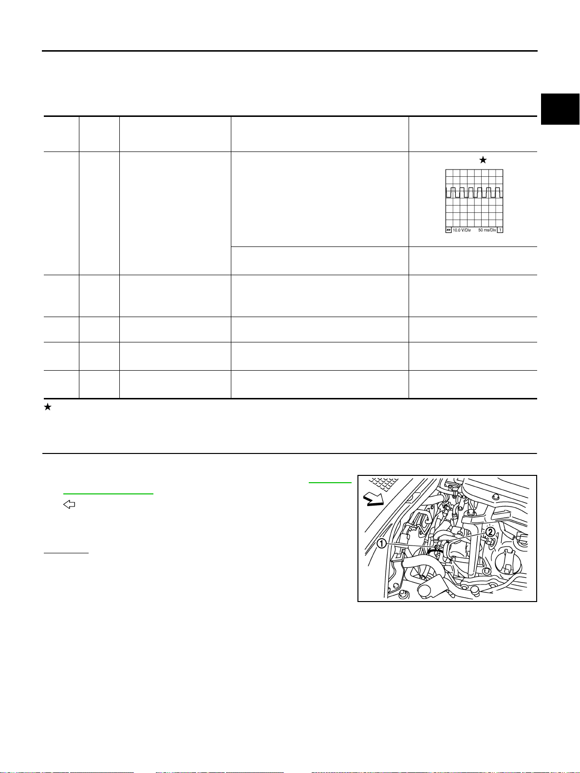
1. CHECK GROUND CONNECTIONS
1. Turn ignition switch OFF.
2. Loosen and retighten ground screws. Refer to EC-1067,
"Ground Inspection" .
– : Vehicle front
– Engine ground E25 (1)
– Engine ground E24 (2)
OK or NG
OK >> GO TO 2.
NG >> Repair or Replace ground connections.
TER-
MINAL
NO.
WIRE
COLOR
ITEM CONDITION DATA (DC Voltage)
34 L A/F sensor 1 heater
[Engine is running]
● After the vehicle is driven for 6 minutes
under the following conditions.
– Warm-up condition
– Vehicle speed: 80km/h (50MPH)
– Shift lever: Suitable gear position
Approximately 5V
[Ignition switch: ON]
● Engine: Stopped
BATTERY VOLTAGE
(11 - 14V)
35 B ECM ground
[Engine is running]
● Warm-up condition
● Idle speed
Approximately 0V
67 —
Sensor ground
(Sensor shield circuit)
[Ignition switch ON] Approximately 0.3V
85 W A/F sensor 1 (-)
[Engine is running]
● Idle speed
1.8 - 2.1V
93 OR A/F sensor 1 (+)
[Engine is running]
● Idle speed
2.2 - 2.5V
PBIB3207E
PBIB3179E
Loading ...
Loading ...
Loading ...