Loading ...
Loading ...
Loading ...
Instrument Functions
R&S
®
NGP800
89User Manual 5601.5610.02 ─ 04
●
Chapter 6.17.2, "Channel Adjustment", on page 92
► Press [Settings] key.
The R&S NGP800 displays the device/channel menu window.
6.17.1 Analog In Adjustment
The "Analog In Adjustment" adjusts the output channel voltage and current when a 0 V
to 5 V is applied at the analog input of the terminal block, see
"Digital I/O & analog
input connector (15)"
on page 26.
Depending on the instrument models, up to four analog input pins are adjusted inde-
pendently.
Table 6-5: Output channel voltage, current for different instrument models
Models Output channel voltage with 0 V to 5 V applied to
analog input pins (ANA IN1, ANA IN2, ANA IN3,
ANA IN4)
NGP802, NGP804, NGP814 (Ch 1, Ch 2) 0 V to 32 V, 0A - 20A
NGP822, NGP824, NGP814 (Ch 3, Ch 4) 0 V to 64 V, 0A - 10A
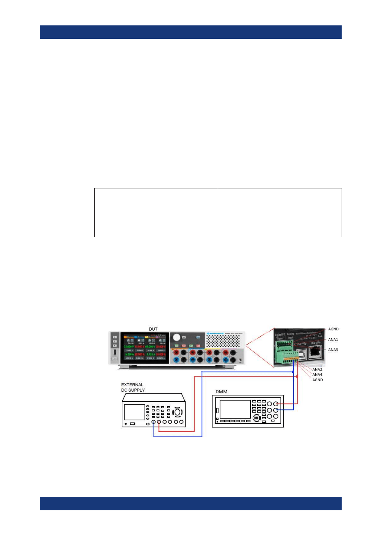
Analog input adjustment setup
Recommended instruments
●
Digital multimeter (DMM): 6 ½ digits
●
External DC power supply: 1 mV resolution, 0.05 % accuracy with < 500 uVrms rip-
ple
Connect the external DC power supply to the
analog input channel (e.g. ANA_IN1)
with respect to the analog ground (AND_GND). Monitor the voltage using digital
multimeter.
Figure 6-40: Analog input adjustment setup
Adjustment
Loading ...
Loading ...
Loading ...