Loading ...
Loading ...
Loading ...
Operating Basics
R&S
®
NGP800
34User Manual 5601.5610.02 ─ 04
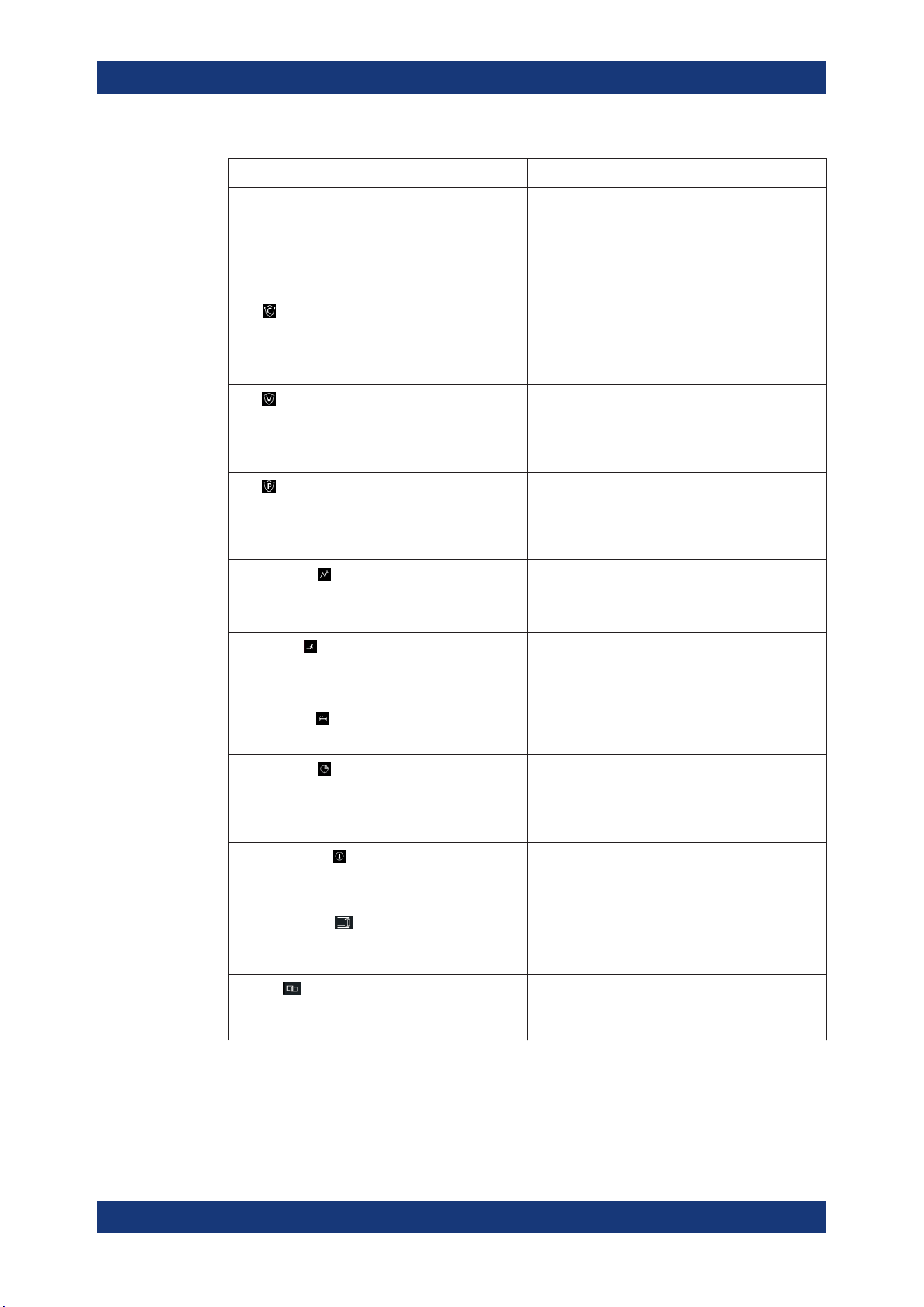
Function Description
Channel number Channel number indication.
Operation mode The R&S NGP800 has two operating modes:
●
CV: Constant voltage mode
●
CC: Constant current mode
See
Chapter 5.5, "Operation Modes", on page 45.
OCP
If enabled, the icon is highlighted in white.
If triggered, the icon blinks.
See Chapter 6.4.1, "Overcurrent Protection (OCP)",
on page 54.
OVP
If enabled, the icon is highlighted in white.
If triggered, the icon blinks.
See Chapter 6.4.2, "Overvoltage Protection (OVP)",
on page 54.
OPP
If enabled, the icon is highlighted in white.
If triggered, the icon blinks.
See Chapter 6.4.3, "Overpower Protection (OPP)",
on page 55.
Arbitrary mode
If enabled, the icon is highlighted in white.
If active, the icon blinks.
See Chapter 6.7.1, "QuickArb", on page 62.
Ramp mode
If enabled, the icon is highlighted in white.
If active, the icon blinks.
See Chapter 6.7.2, "EasyRamp", on page 65.
"Safety Limits"
If enabled, the icon is highlighted in white.
See Chapter 6.4.4, "Safety Limits", on page 56.
"Output Delay"
If enabled, the icon is highlighted in white.
The delay is the time between activation of the out-
put and applying voltage to the output.
See Chapter 6.2.1, "Output", on page 49.
Adjustment mode
If user adjustment is active, the icon is highlighted in
red.
See Chapter 6.17, "Adjustment", on page 88.
Sense connection
If sense connection is detected, the icon is highligh-
ted in white.
See Chapter 6.2.1, "Output", on page 49.
Tracking
If tracking is enabled, the icon is highlighted in
white.
See Chapter 6.5, "Tracking Function", on page 57.
Display Overview
Loading ...
Loading ...
Loading ...