Loading ...
Loading ...
Loading ...
Instrument Functions
R&S
®
NGP800
59User Manual 5601.5610.02 ─ 04
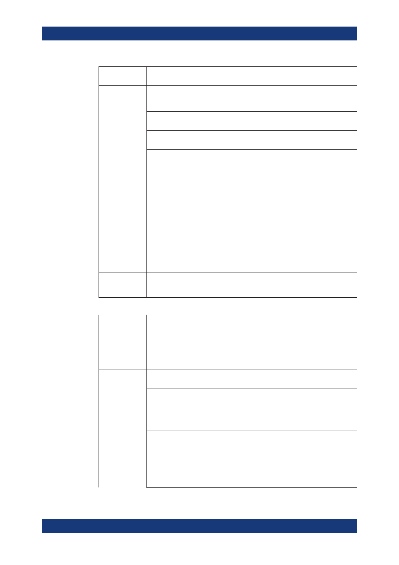
Trigger in
parameters
Trigger conditions Description
"Arb Step Group" Selected channel QuickArb function steps to
the next group when the selected logic level
is met.
"Ramp" Selected channel EasyRamp function is
enabled when the selected logic level is met.
"Logging" Selected channel logging function is enabled
when the selected logic level is met.
"Statistics" Selected channel statistics function is
enabled when the selected logic level is met.
"AnalogIn" Selected channel analog input is enabled
when the selected logic level is met.
"Inhibit" Selected channel output is inhibited when
the selected logic level is met.
If the selected channel output is put to inhibit
state, manual or remote operation on
selected channel output is no longer possi-
ble .
To reverse the inhibit state, remove the
source of the trigger signal. You can either
disable the affected DIO interface or remove
the source from the affected DIO interface at
the rear panel.
Active Level High Set the logic level of the trigger in signal.
Low
Table 6-2: Trigger out parameters and conditions
Trigger out
parameters
Trigger conditions Description
Channel "--", "Ch 1", "Ch 2", "Ch 3", "Ch 4" Output channel selected to monitor for trig-
ger conditions.
If "--" is selected, no channel is selected for
trigger response.
Mode Output Output the selected logic level when the out-
put is turned on at the selected channel.
Fuse Output the selected logic level when a fuse
tripped event occurs on the selected chan-
nel.
See Chapter 6.4.1, "Overcurrent Protection
(OCP)", on page 54 .
Operation mode
●
"CC": Output the selected logic level
when the selected channel operates in
the CC mode. See "CC mode"
on page 46.
●
"CV": Output the selected logic level
when the selected channel operates in
the CV mode. See
"CC mode"
on page 46.
Digital Trigger I/O
Loading ...
Loading ...
Loading ...