Loading ...
Loading ...
Loading ...
Instrument Functions
R&S
®
NGP800
60User Manual 5601.5610.02 ─ 04
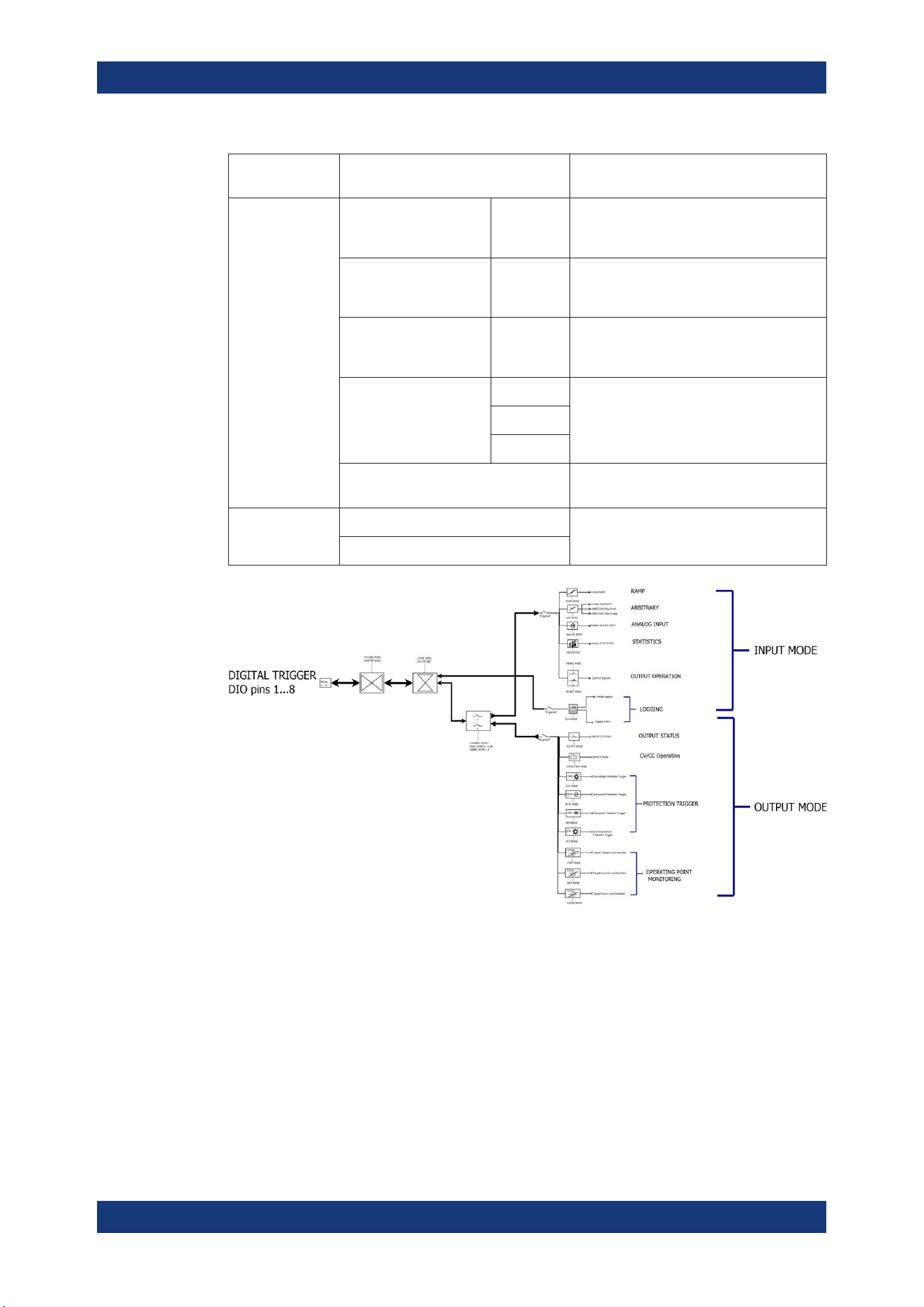
Trigger out
parameters
Trigger conditions Description
Voltage Level, "Vset" >= "set
value"
Output the selected logic level when the
voltage level of the selected channel is
greater or equal to the set voltage level.
Current Level, "Iset" >= "set
value"
Output the selected logic level when the cur-
rent level of the selected channel is greater
or equal to the set current level.
Power Level, "Plevel" >= "set
value"
Output the selected logic level when the
power level of the selected channel is
greater or equal to the set power level.
Critical event "OVP" Output the selected logic level when the
selected critical event ("OVP", "OPP",
"OTP") occurs on the selected channel. See
Chapter 6.4, "Protection", on page 53.
"OPP"
"OTP"
"Logging" Output the selected logic level when the log-
ging is enabled.
Active Level High Set the logic level of the trigger out signal.
Low
Figure 6-10: DIO trigger block diagram
1. Press [Settings] key.
The R&S NGP800 displays the device/channel menu window.
2. Select the device tab to configure digital I/O trigger.
The R&S NGP800 displays the "Digital Trigger Menu" dialog.
Digital Trigger I/O
Loading ...
Loading ...
Loading ...