Loading ...
Loading ...
Loading ...
Getting Started
R&S
®
NGP800
23User Manual 5601.5610.02 ─ 04
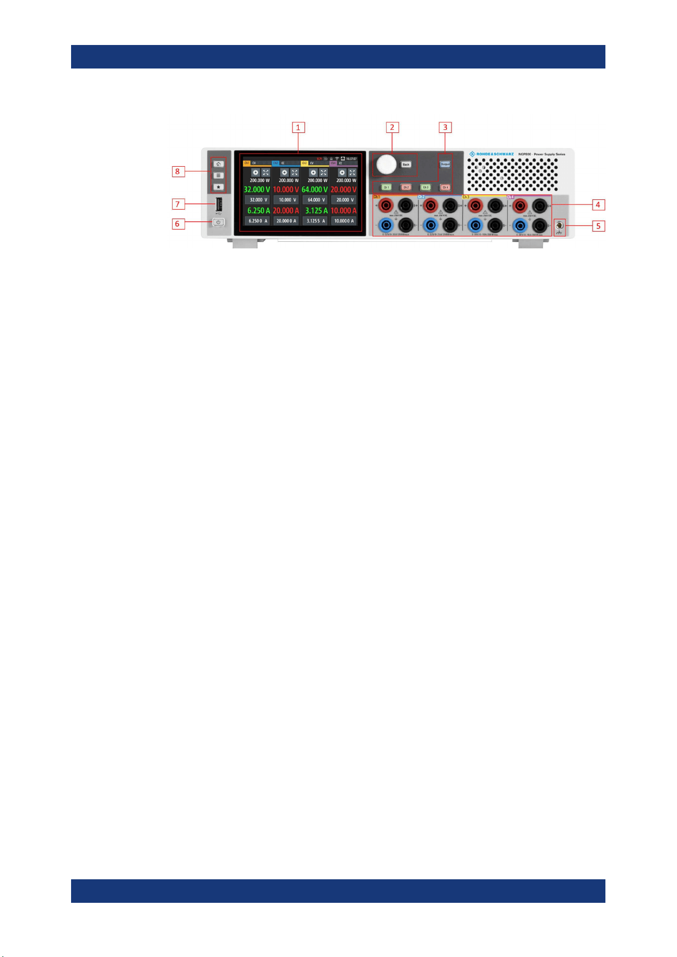
Figure 4-2: Front panel of R&S
NGP800 power supply
1 = Display with touch screen
2 = Rotary knob and back key
3 = Output and channel keys
4 = Output terminals (see
Table 4-2)
5 = Chassis ground terminal (4mm socket)
6 = Standby button
7 = USB connector
8 = Menu control keys
Display (1)
The display is a color TFT touch screen. Depending on the instrument models, up to
four channels are shown on the display. The respective measurement settings and
menu settings are displayed in the individual channel display area.
Two information status bars, providing the overall device operating mode and channel
settings of the instrument are located respectively at the device level (top-right hand
corner of the display area) and channel level (on top of individual channel display area)
of the instrument.
For a detailed description on-screen layout, see section "Display Overview" in the User
Manual.
Rotary knob and back key (2)
The rotary knob and back key are used for menu navigation and value adjustment in
the instrument.
For a detailed description on navigation, see section "Rotary Knob and Back Key" in
the User Manual.
Output and channel keys (3)
Depending on the instrument models, up to four channels and one output key are pro-
vided to select individual channel and enable/disable the output(s).
Output terminals (4)
Two-channel instruments: NGP802 and NGP822 are equipped with 8 terminals for out-
puts and remote sense connections. Four-channel instruments: NGP804, NGP814 and
NGP824 are equipped with 16 terminals for outputs and remote sense connections.
Instrument Tour
Loading ...
Loading ...
Loading ...