Loading ...
Loading ...
Loading ...
Getting Started
R&S
®
NGP800
26User Manual 5601.5610.02 ─ 04
The channel terminal blocks contain connections to both outputs (“+”,”-“) and remote
sense (“+Sense”,”-Sense”). Terminal block for channel 3 and channel 4 are only availa-
ble for a 4-channel instrument.
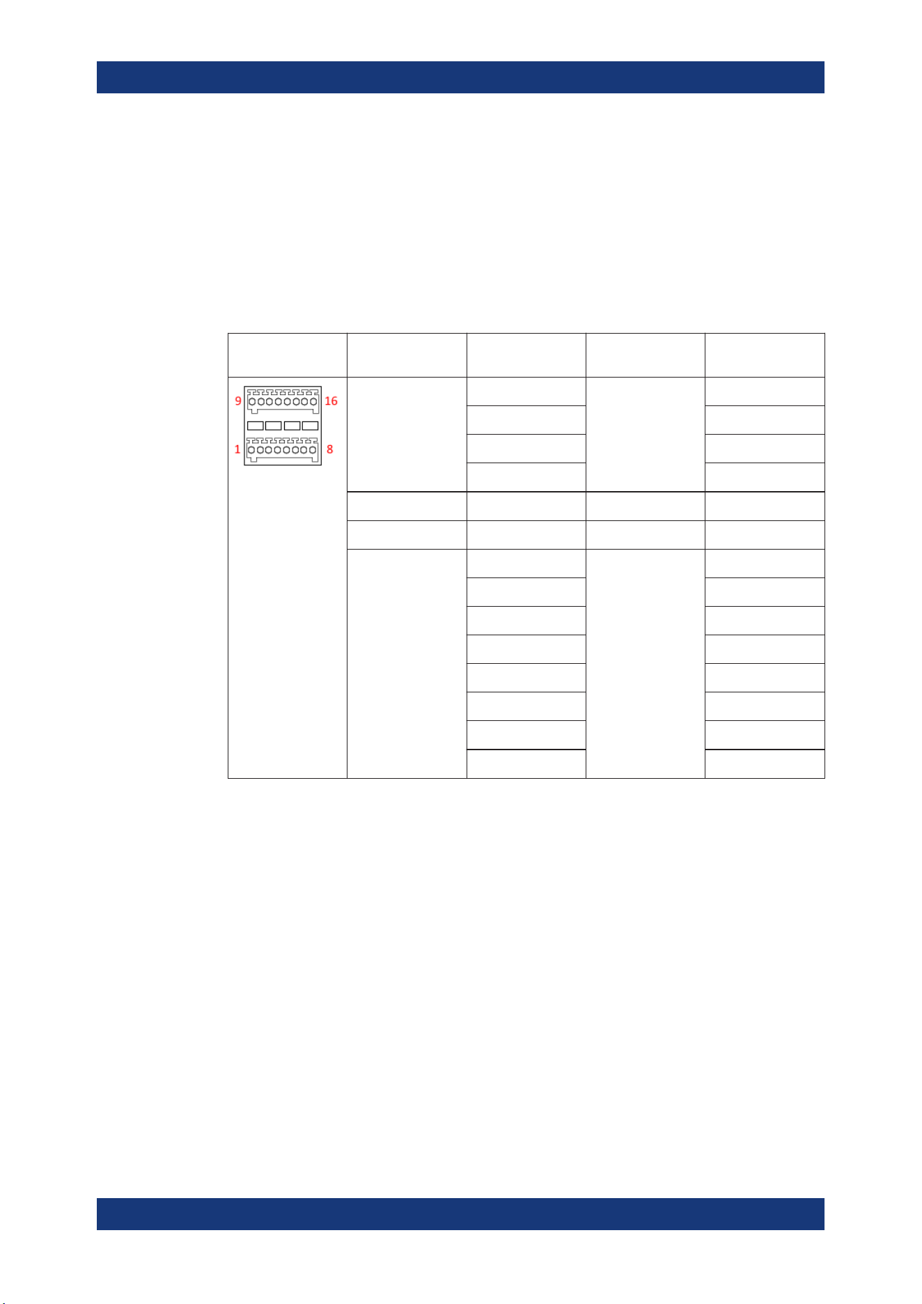
Digital I/O & analog input connector (15)
A 16-pin terminal block provides connection to both digital I/O (option NGP-K103) and
analog input (option NGP-K107). See
Table 4-3.
Table 4-3: Pin configurations
DIO & analog
input connector
Signal Logical name Value range Pin number
Analog input 1 to 4 ANA1 0 Vdc to 5 Vdc 16
ANA2 8
ANA3 15
ANA4 7
Analog ground GND 0 Vdc 6, 14
Digital ground GND 0 Vdc 5, 13
Digital trigger 1 to 8 DIO1 TTL 12
DIO2 4
DIO3 11
DIO4 3
DIO5 10
DIO6 2
DIO7 9
DIO8 1
USB connector (16)
USB Type-B connector provides remote control operation via USB.
Ethernet connector (17)
10/100 Ethernet port for remote control operation via the local area network.
4.2.2 Switching On the Instrument
Before switching on the instrument, check that all the instructions in the “Basic Safety
Instruction” brochure and safety measures in previous sections are observed.
To switch on instrument:
1. Connect the power cable to the AC power connector at the rear panel of the
R&S NGP800 power supply.
Instrument Tour
Loading ...
Loading ...
Loading ...