Loading ...
Loading ...
Loading ...
En
42
Setting the various parameters of LFO
Turn the parameter adjustment knobs to set the values of [SPEED],
[DEPTH], and [PAHSE OFFSET]. An explanation and the setting range of
each parameter are provided below.
SPEED
Turn the parameter 1 adjustment knob to set the frequency of LFO. The
setting range will vary as follows depending on whether the [SYNC] but-
ton is ON or OFF.
!
SYNC When OFF: 0 to 127
! SYNC When ON: 1/2, ,1, 2, 3, 4, 8, 12, 16, 32, 48, 64, 128 (unit: STEP)
DEPTH
Turn the parameter 2 adjustment knob to set the application amount to
apply to the parameter selected in [DESTINATION]. The range is -64 to
0 to 63.
!
When the DEPTH value is a minus value, the top and bottom of the
waveform will be inverted.
! A waveform is displayed in the LFO waveform display section in
accordance with the DEPTH value.
PHASE OFFSET
Turn the parameter 3 adjustment knob to set the initial position of LFO.
The range is 0% to 99%.
! The initial position of LFO at 99% will be delayed by about 1 cycle.
! A waveform is displayed in the LFO waveform display section in
accordance with the PHASE OFFSET value.
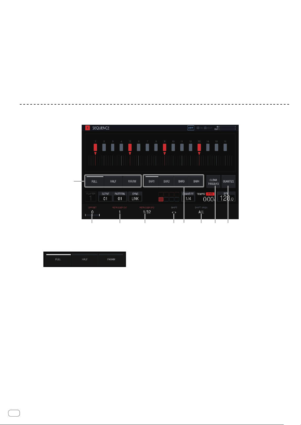
Adjusting various trigger sequences (SEQUENCE)
The trigger sequence of each track can be offset and otherwise adjusted with a unit smaller than steps.
2 3 4 5
7 8 9
1
6
1 Trigger type selection
Selects the type of triggers to input.
The default is [Full].
1 Full trigger (Full)
SAMPLE, ENVELOPE, and all modulated parameters are
triggered.
2
Half trigger (HALF)
ENVELOPE and modulated parameters are triggered.
3 Parameter trigger (PARAM)
Only modulated parameters are triggered.
2 OFFSET
A trigger can be finely adjusted forward or backward. It can be
adjusted up to ±1 step (indicating line is directly below the adjacent
step).
Move the trigger position [b] on the touch display a very small
amount by operating this parameter.
!
The default is 0.
3 RETRIGGER CNT
Sets the number of times to input triggers repeatedly over a short
period.
!
The default is 1.
! When [RETRIGGER CNT] is two or more, the [b] mark on the
screen is changed to the mark for indicating repeated input (two
[b] marks arranged vertically).
4 RETRIGGER SPD
Sets the speed for re-triggering.
!
The default is 1/32 (BAR).
! When [RETRIGGER CNT] is two or more, the [b] mark on the
screen is changed to the mark for indicating repeated input (two
[b] marks arranged vertically).
5 SHIFT
An input trigger can be offset by step (circle shift) within the range
set in [SHIFT AREA].
6 BAR
This is linked to the bar selection button and the bar to be displayed
can be selected. It also indicates the bar currently displayed.
7 SHIFT AREA
Sets the range to apply [SHIFT].
This can be selected from the two types, [BAR] and [ALL].
! Specify the operation target step with the hardware buttons.
When no step has been specified, all steps become targets. For
example, all steps are uniformly offset in the case of an offset.
When an individual step is selected by pressing a step key, the
corresponding vertically long [g] and [b] on the touch display
flash.
8 CLEAR TRIGGERS
Clears all of the triggers input to the currently selected pattern.
9 QUANTIZE
Snaps the triggers input to the currently selected pattern on a 1/16
level.
Loading ...
Loading ...
Loading ...