Loading ...
Loading ...
Loading ...
Instrument Functions
R&S
®
NGL200/NGM200
66User Manual 1178.8736.02 ─ 09
4. Select "Enable" and set it "On" to enable the trigger-in setting.
5.
Select "Back"
to go back to "Device" menu.
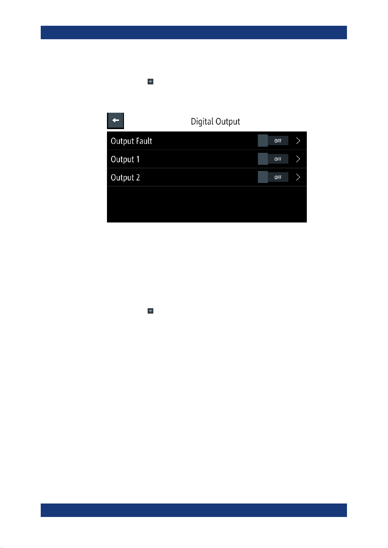
6. Select "Digital Output" to configure the trigger-out parameter.
The R&S NGL/NGM displays the "Digital Output" dialog.
Figure 6-21: Digital Out dialog
7. Depending on your requirements, select the digital output accordingly.
The two Digital I/O output pins OUT1 and OUT2 can be set directly by the SCPI
commands. See
DIO:OUTPut[:STATe] on page 158.
See also
Figure 6-18 for details of the trigger-out parameters.
8. Select the respective "Digital Output" menu items and set "On" to enable the trig-
ger-out parameters.
9.
Select "Back"
to go back to "Device" menu.
10. If "User Button" is set as a trigger-in signal, select "User Button" menu item.
The R&S NGL/NGM displays the "User Button" dialog.
See also
Chapter 6.8, "User Key", on page 71.
11. Select "User Button Action" and set as "Trigger".
The R&S NGL/NGM generates a trigger-in signal when user button key is pressed.
12. If "Logging" is set as a trigger-out signal, select "Logging" menu item.
The R&S NGL/NGM displays the "Logging" dialog.
See also
Chapter 6.10, "Data Logging", on page 73.
13. Select "Triggered" and set as "On".
The R&S NGL/NGM starts the data logging of the instrument when a trigger is
detected.
14. If "Arbitrary" is set as a trigger-out signal, select "Arbitrary" menu item from the
respective channel menu.
The R&S NGL/NGM displays the "Arbitrary" dialog.
See also
Chapter 6.7.1, "Arbitrary", on page 67.
Trigger / Digital I/O
Loading ...
Loading ...
Loading ...