Loading ...
Loading ...
Loading ...
Instrument Functions
R&S
®
NGL200/NGM200
63User Manual 1178.8736.02 ─ 09
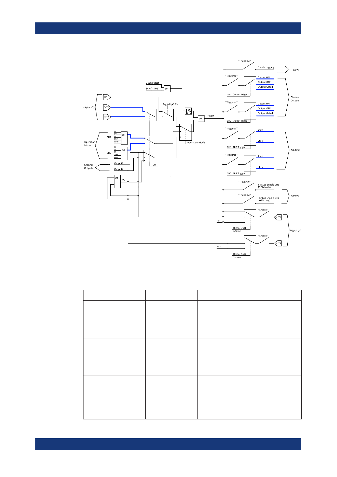
Figure 6-18: Overview of trigger IO system
Table 6-3: Trigger-in signals
Trigger-in parameters Source Descriptions
Ext. Trigger Ch1
Ext. Trigger Ch2
Digital In, pin 2 of Digi-
tal I/O connector
Digital In, pin 10 of Dig-
ital I/O connector
If detected, corresponding trigger-out parameters
are triggered.
The external trigger signal is low active (inverted
logic).
See Figure 6-18.
Digital I/O In1 Digital In, pin 3 of Digi-
tal I/O connector
If detected, corresponding trigger-out parameters
are triggered.
The Digital I/O In1 signal is low active (inverted
logic).
See Figure 6-18.
Output channel 1
Output channel 2
Any of the channels
Output If respective channel output is turned on, corre-
sponding trigger-out parameters are triggered.
If "Any" is selected, the corresponding trigger-out
parameters are triggered if any of the available
channels meet the condition.
See Figure 6-18.
Trigger / Digital I/O
Loading ...
Loading ...
Loading ...