Loading ...
Loading ...
Loading ...
Instrument Functions
R&S
®
NGL200/NGM200
55User Manual 1178.8736.02 ─ 09
Table 6-2: Battery simulator parameters
Battery simulator parameters Descriptions
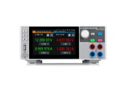
The battery symbol represents the state of charge.
The light blue bar indicates the open circuit voltage
and the dark blue bar indicates the terminal voltage.
The differences between both bars show the voltage
drops on internal resistance.
Scale: the maximum of both bars are the maximum
defined voltage in the battery model and the mini-
mum is the minimal defined voltage.
See Figure 6-13.
SoC State of charge represents the current battery
capacity, e.g. 85% SoC represents that 15% of bat-
tery capacity is used.
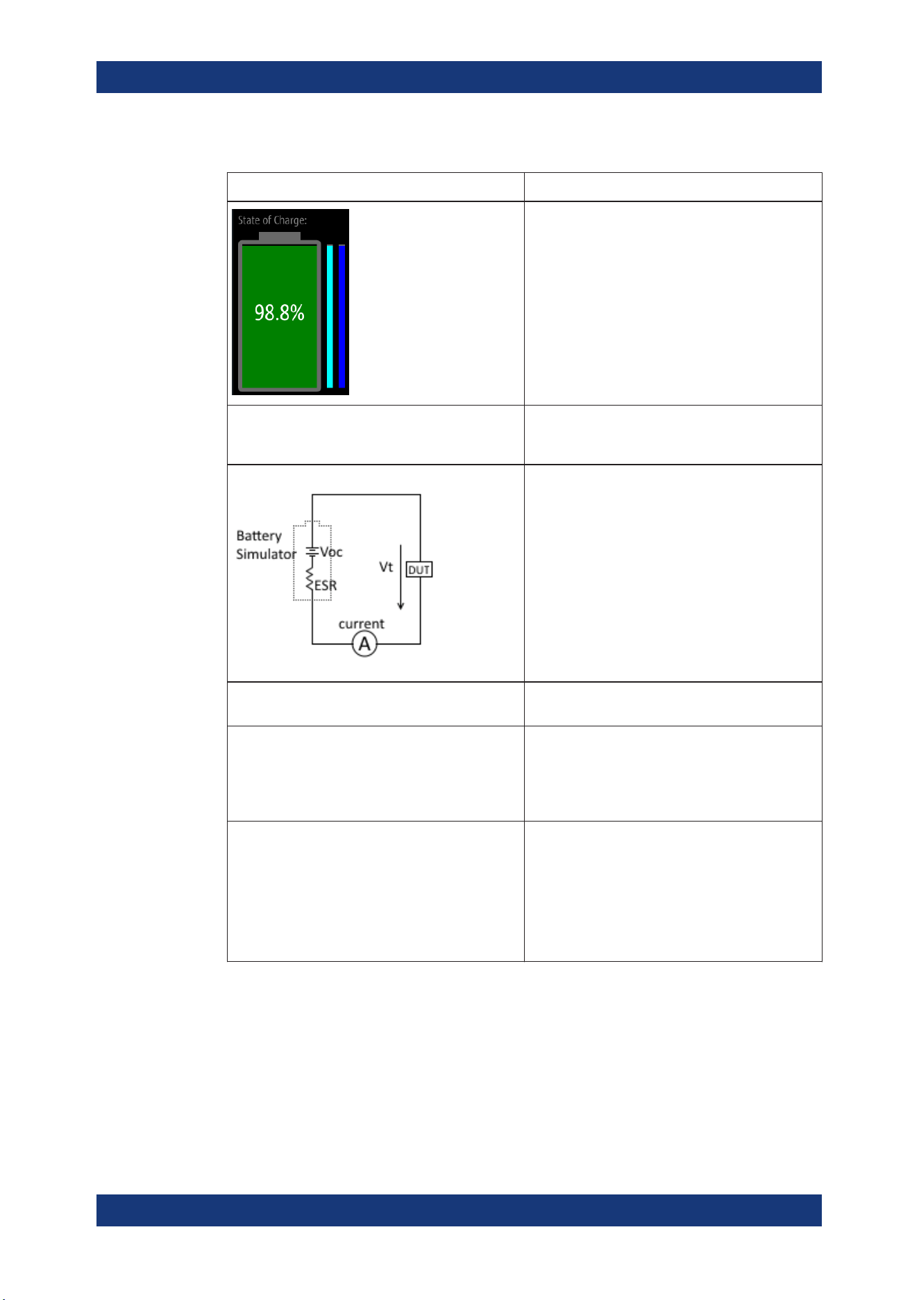
The open circuit voltage, Voc is the voltage between
the battery terminals with no load applied. The Voc
depends on the loaded battery model and the cur-
rent SoC.
The internal resistance, ESR (also known as Equiv-
alent Series Resistance) depends on the loaded
battery model and current SoC.
The terminal voltage, Vt is the voltage between the
battery terminals with applied voltage drop over the
ESR. Terminal voltage varies with charge or dis-
charge current.
Model The loaded battery model applied in the battery sim-
ulator.
Battery capacity The storage capacity for the battery:
●
Minimum value: 1 µAh
●
Maximum value: 100 kAh
Editing a new value here overwrites the current
value loaded from the
battery model editor.
Current limit In addition to the resistance of the battery model,
current flow can be limited to protect possibly sensi-
tive equipment connected to the device.
There are three current limit settings available:
●
SoC < 0 % (the battery is empty)
●
SoC 0 % to 100 % (the battery is in normal
operation mode)
●
SoC > 100 % (the battery is fully loaded)
1. Press [Settings] key.
The R&S NGM displays the device/channel menu window.
2. Select the required channel tab to configure the battery simulator function.
The R&S NGM displays the selected channel menu.
3. Select the "Battery Simulator" menu item from the menu.
The R&S NGM displays the "Battery Simulator" dialog.
Battery Simulator
Loading ...
Loading ...
Loading ...