R&S
®
NGL200/NGM200
Power Supply Series
User Manual
1178873602
Version 09
(;ÜåT2)

This manual describes the following R&S
®
NGL/NGM models with firmware version 1.00 or higher:
●
R&S
®
NGL201 Single-channel power supply 60W (3638.3376.02)
●
R&S
®
NGL202 Two-channel power supply 120W (3638.3376.03)
●
R&S
®
NGM201 Single-channel power supply 60W (3638.4472.02)
●
R&S
®
NGM202 Two-channel power supply 120W (3638.4472.03)
In addition to the base unit, the following options are described:
●
R&S
®
NGL-B105 Option IEEE-488 (GPIB) Interface (3652.6356.02)
●
R&S
®
NGL-K102 Option Wireless LAN Remote Control (3652.6362.02)
●
R&S
®
NGL-K103 Option Digital I/O (3652.6385.02)
●
R&S
®
NGM-B105 Option IEEE-488 (GPIB) interface (3641.6220.02)
●
R&S
®
NGM-K102 Option Wireless LAN Remote Control (3644.6367.02)
●
R&S
®
NGM-K103 Option Digital I/O (3643.9904.02)
●
R&S
®
NGM-K104 Option Digital Voltmeter (3643.9927.02)
●
R&S
®
NGM-K106 Option Battery Simulation (3636.6626.02)
© 2020 Rohde & Schwarz GmbH & Co. KG
Mühldorfstr. 15, 81671 München, Germany
Phone: +49 89 41 29 - 0
Email:
Internet: www.rohde-schwarz.com
Subject to change – data without tolerance limits is not binding.
R&S
®
is a registered trademark of Rohde & Schwarz GmbH & Co. KG.
Trade names are trademarks of the owners.
1178.8736.02 | Version 09 | R&S
®
NGL200/NGM200
Throughout this manual, products from Rohde & Schwarz are indicated without the
®
symbol, e.g. R&S
®
NGL200, R&S
®
NGM200 are
indicated as R&S NGL/NGM.

1171.1307.42 - 05
1
Safety Instructions
Instrucciones de seguridad
Sicherheitshinweise
Consignes de sécurité
Risk of injury and instrument damage
The instrument must be used in an appropriate manner to prevent
electric shock, fire,
personal injury or instrument damage.
●
Do not open the instrument casing.
●
Read and observe the "Basic Safety Instructions" delivered as
printed brochure with the instrument.
●
Read and observe the safety instructions in the following sections.
Note that the data sheet may specify additional operating conditions.
●
Keep the "Basic Safety Instructions" and the product documentation
in a safe place and pass them on to the subsequent users.
Riesgo de lesiones y daños en el instrumento
El instrumento se debe usar de manera adecuada para p
revenir
descargas eléctricas, incendios, lesiones o daños materiales.
●
No abrir la carcasa del instrumento.
●
Lea y cumpla las "Instrucciones de seguridad elementales"
suministradas con el instrumento como folleto impreso.
●
Lea y cumpla las instrucciones de seguridad incluidas en las
siguientes secciones. Se debe tener en cuenta que las
especificaciones técnicas pueden contener condiciones adicionales
para su uso.
●
Guarde bien las instrucciones de seguridad elementales, así como
la documentación del producto, y entréguelas a usuarios
posteriores.

1171.1307.42 - 05
2
Gefahr von Verletzungen und Schäden am Gerät
Betreiben Sie das Gerät immer ordnungsgemäß, um elektrischen
Schlag, Brand, Verletzungen von Personen oder Geräteschäden zu
verhindern.
●
Öffnen Sie das Gerätegehäuse nicht.
●
Lesen und beachten Sie die "Grundlegenden Sicherheitshinweise",
die als gedruckte Broschüre dem Gerät beiliegen.
●
Lesen und beachten Sie die Sicherheitshinweise in den folgenden
Abschnitten; möglicherweise enthält das Datenblatt weitere
Hinweise zu speziellen Betriebsbedingungen.
●
Bewahren Sie die "Grundlegenden Sicherheitshinweise" und die
Produktdokumentation gut auf und geben Sie diese an weitere
Benutzer des Produkts weiter.
Risque de blessures et d'endommagement de l'appareil
L'ap
pareil doit être utilisé conformément aux prescriptions afin d'éviter
les électrocutions, incendies, dommages corporels et matériels.
●
N'ouvrez pas le boîtier de l'appareil.
●
Lisez et respectez les "consignes de sécurité fondamentales"
fournies avec l’appareil sous forme de brochure imprimée.
●
Lisez et respectez les instructions de sécurité dans les sections
suivantes. Il ne faut pas oublier que la fiche technique peut indiquer
des conditions d’exploitation supplémentaires.
●
Gardez les consignes de sécurité fondamentales et la
documentation produit dans un lieu sûr et transmettez ces
documents aux autres utilisateurs.

Contents
R&S
®
NGL200/NGM200
3User Manual 1178.8736.02 ─ 09
Contents
1 Documentation Overview......................................................................9
1.1 Manuals..........................................................................................................................9
1.2 Data Sheet....................................................................................................................10
1.3 Release Notes, Open Source Acknowledgment...................................................... 10
1.4 Application Notes, Application Cards, Videos......................................................... 10
2 Welcome to R&S NGL/NGM.................................................................11
3 Important Notes....................................................................................12
3.1 Symbols....................................................................................................................... 12
3.2 Ambient Conditions.................................................................................................... 12
3.3 Measurement Categories........................................................................................... 13
3.4 Mains Voltage.............................................................................................................. 13
3.5 Limits............................................................................................................................14
4 Getting Started..................................................................................... 15
4.1 Putting into Operation................................................................................................ 15
4.1.1 Safety............................................................................................................................ 16
4.1.2 Intended Operation....................................................................................................... 17
4.1.3 Unpacking and Checking the Instrument...................................................................... 19
4.1.4 Setting Up the Instrument............................................................................................. 19
4.1.4.1 Bench Operation........................................................................................................... 19
4.1.4.2 Rack Mounting.............................................................................................................. 20
4.2 Instrument Tour........................................................................................................... 20
4.2.1 Overview of Controls.....................................................................................................20
4.2.1.1 Front Panel....................................................................................................................20
4.2.1.2 Rear Panel.................................................................................................................... 22
4.2.2 Switching On the Instrument......................................................................................... 24
4.3 Trying Out the Instrument.......................................................................................... 25
4.3.1 Setting the Output Voltage and Current........................................................................ 26
4.3.2 Activating the Channels Output.....................................................................................26
4.4 Maintenance and Support.......................................................................................... 27
4.4.1 Maintenance..................................................................................................................27

Contents
R&S
®
NGL200/NGM200
4User Manual 1178.8736.02 ─ 09
4.4.2 Contacting Customer Support.......................................................................................28
5 Operating Basics..................................................................................29
5.1 Display Overview........................................................................................................ 29
5.1.1 Status Bar Information.................................................................................................. 29
5.1.2 Channel Display Area................................................................................................... 32
5.2 Using the Touchscreen...............................................................................................33
5.2.1 Using Gestures............................................................................................................. 33
5.2.2 Accessing Functionality in the Home Window.............................................................. 33
5.2.2.1 Settings Button..............................................................................................................34
5.2.2.2 Voltage and Current Inputs........................................................................................... 35
5.2.2.3 Expand/Collapse Button................................................................................................35
5.2.3 Input Data......................................................................................................................36
5.3 Front Panel Keys.........................................................................................................37
5.3.1 Menu Controls...............................................................................................................37
5.3.1.1 Home Key..................................................................................................................... 37
5.3.1.2 Settings Key.................................................................................................................. 37
5.3.1.3 User Key....................................................................................................................... 40
5.3.2 Navigation Controls.......................................................................................................40
5.3.3 Output and Channel Controls........................................................................................41
5.4 Power Derating............................................................................................................41
5.5 Operation Modes.........................................................................................................42
6 Instrument Functions.......................................................................... 44
6.1 Setting the Channels Voltage and Current............................................................... 44
6.2 Activating the Channels Output................................................................................ 45
6.2.1 Set Constant Resistance...............................................................................................46
6.2.2 Fast Transient Response.............................................................................................. 47
6.2.3 Output........................................................................................................................... 48
6.2.3.1 Impedance.................................................................................................................... 48
6.2.3.2 Delay............................................................................................................................. 49
6.2.3.3 Trigger Events............................................................................................................... 50
6.2.3.4 Output Mode................................................................................................................. 51
6.3 Ranges / Digital Voltmeter (DVM)...............................................................................52
6.4 Battery Simulator........................................................................................................ 54

Contents
R&S
®
NGL200/NGM200
5User Manual 1178.8736.02 ─ 09
6.5 Protection.................................................................................................................... 58
6.5.1 Overcurrent Protection (OCP).......................................................................................58
6.5.2 Overvoltage Protection (OVP).......................................................................................59
6.5.3 Overpower Protection (OPP)........................................................................................ 60
6.5.4 Safety Limits..................................................................................................................61
6.6 Trigger / Digital I/O...................................................................................................... 62
6.7 Advanced Features..................................................................................................... 67
6.7.1 Arbitrary.........................................................................................................................67
6.7.2 Ramp.............................................................................................................................70
6.8 User Key.......................................................................................................................71
6.9 Screenshot...................................................................................................................72
6.10 Data Logging............................................................................................................... 73
6.11 FastLog........................................................................................................................ 75
6.12 CSV Settings................................................................................................................76
6.13 Graphical View Window..............................................................................................78
6.14 File Manager................................................................................................................ 80
6.15 Store and Recall ......................................................................................................... 81
6.16 Interfaces..................................................................................................................... 83
6.16.1 Network Connection......................................................................................................84
6.16.1.1 LAN Connection............................................................................................................ 85
6.16.1.2 Wireless LAN Connection............................................................................................. 87
6.16.2 USB Connection............................................................................................................88
6.16.3 GPIB Address............................................................................................................... 89
6.17 General Instrument Settings...................................................................................... 90
6.17.1 Licenses Management.................................................................................................. 90
6.17.2 Appearance Settings.....................................................................................................92
6.17.3 Sound Settings..............................................................................................................92
6.17.4 Date and Time...............................................................................................................93
6.17.5 Device Information........................................................................................................ 94
6.17.6 Update Device...............................................................................................................94
6.18 Device Documentation............................................................................................... 95
7 Remote Control Commands................................................................96
7.1 Common Setting Commands.....................................................................................96

Contents
R&S
®
NGL200/NGM200
6User Manual 1178.8736.02 ─ 09
7.2 System Settings Commands......................................................................................99
7.3 Display Commands...................................................................................................101
7.4 Trigger Commands................................................................................................... 102
7.5 Configuration Commands........................................................................................ 105
7.5.1 Channel Selection....................................................................................................... 106
7.5.2 Safety Limit Setting..................................................................................................... 107
7.5.3 Voltage Setting.............................................................................................................111
7.5.4 Current Setting............................................................................................................ 114
7.5.5 Resistance Setting.......................................................................................................117
7.5.6 Combined Setting of Voltage and Current Setting.......................................................119
7.5.7 Output Setting............................................................................................................. 120
7.5.8 Range/DVM Setting.................................................................................................... 126
7.5.9 OCP Setting................................................................................................................ 129
7.5.10 OVP Setting................................................................................................................ 136
7.5.11 OPP Setting................................................................................................................ 139
7.5.12 USB Class Setting.......................................................................................................142
7.6 Measurement Commands........................................................................................ 142
7.7 Advanced Operating Commands............................................................................ 149
7.7.1 Arbitrary.......................................................................................................................149
7.7.2 Ramp...........................................................................................................................155
7.7.3 Digital I/O.................................................................................................................... 156
7.7.4 Battery Simulation....................................................................................................... 159
7.8 Data and File Management Commands.................................................................. 166
7.9 Status Reporting Commands...................................................................................175
7.9.1 STATus:OPERation Registers.....................................................................................175
7.9.2 STATus:QUEStionable Registers................................................................................177
Annex.................................................................................................. 180
A Additional Basics on Remote Control..............................................180
A.1 Messages and Command Structure........................................................................ 180
A.1.1 Messages....................................................................................................................180
A.1.2 SCPI Command Structure...........................................................................................181
A.2 Command Sequence and Synchronization............................................................ 185
A.2.1 Preventing Overlapping Execution..............................................................................186

Contents
R&S
®
NGL200/NGM200
7User Manual 1178.8736.02 ─ 09
A.3 Status Reporting System......................................................................................... 186
A.3.1 Structure of a SCPI Status Register............................................................................186
List of Commands..............................................................................192
Index....................................................................................................197

Contents
R&S
®
NGL200/NGM200
8User Manual 1178.8736.02 ─ 09

Documentation Overview
R&S
®
NGL200/NGM200
9User Manual 1178.8736.02 ─ 09
1 Documentation Overview
This section provides an overview of the R&S NGL/NGM user documentation.
1.1 Manuals
You find the documents on the R&S NGL/NGM product page at:
www.rohde-schwarz.com/product/ngl200
www.rohde-schwarz.com/product/ngm200
Getting Started
Introduces the R&S NGL/NGM power supply series and describes how to set up and
start working with the instrument. The printed document is delivered with the instru-
ment.
User manual
Contains the description of all instrument modes and functions. It also provides an
introduction to remote control, a complete description of the remote control commands
with programming examples, and information on maintenance and instrument interfa-
ces. Includes the contents of the getting started manual.
The online version of the user manual provides the complete contents for immediate
display on the internet.
Basic safety instructions
Contains safety instructions, operating conditions and further important information.
The printed document is delivered with the instrument.
Instrument security procedures manual
Deals with security issues when working with the R&S NGL/NGM in secure areas.
Service manual
Describes the performance test for checking the rated specifications, module replace-
ment and repair, firmware update, troubleshooting and fault elimination, and contains
mechanical drawings and spare part lists. The service manual is available for regis-
tered users on the global Rohde & Schwarz information system (GLORIS,
https://
gloris.rohde-schwarz.com
).
Manuals

Documentation Overview
R&S
®
NGL200/NGM200
10User Manual 1178.8736.02 ─ 09
1.2 Data Sheet
The datasheet contains the technical specifications of the R&S NGL/NGM power sup-
ply series. It also lists all options with their order numbers and accessories.
See
www.rohde-schwarz.com/brochure-datasheet/ngl200
See www.rohde-schwarz.com/brochure-datasheet/ngm200
1.3 Release Notes, Open Source Acknowledgment
The release notes list new features, improvements and known issues of the current
firmware version, and describe the firmware installation. The open source acknowledg-
ment document provides verbatim license texts of the used open source software. It
can also be read directly on the instrument.
See
www.rohde-schwarz.com/firmware/ngl200.
See
www.rohde-schwarz.com/firmware/ngm200.
1.4 Application Notes, Application Cards, Videos
These documents contain information about possible applications and background
information on various topics,
See
www.rohde-schwarz.com/appnotes/ngl.
See
www.rohde-schwarz.com/appnotes/ngm.
Application Notes, Application Cards, Videos

Welcome to R&S NGL/NGM
R&S
®
NGL200/NGM200
11User Manual 1178.8736.02 ─ 09
2 Welcome to R&S NGL/NGM
The one or two-channel power supply series are based on a classical transformer con-
cept with linear regulators. This concept allows the instrument to achieve highest accu-
racy and lowest residual ripple.
The R&S NGL/NGM power supply series feature galvanically isolated, floating over-
load and short-circuit proof outputs. When multiple channels are connected in parallel,
higher currents can be achieved. When connected in serial, higher voltages are ach-
ievable.
Multi-purpose protection functions are available for each channel which you can set
separately, such as overcurrent protection (OCP), overvoltage protection (OVP) and
overpower protection (OPP). If such a limit is reached, the affected output channel is
automatically turned off and an indicator icon (
, , ) blinks on the display. In the
case of two-channel power supply (NGL202, NGM202), the overcurrent protection can
be linked to the other channel. In this case, the linked channel is turned off when the
other channel reaches a limit.
Additionally, the R&S NGL/NGM is protected with overtemperature protection (OTP).
This safety feature protects the R&S NGL/NGM from overheating. When the tempera-
ture in the power supply exceeds the OTP limit, the channel outputs are automatically
cut off.
The Arbitrary function allows a freely definable voltage and current sequences with a
timeframe as short as 1 ms. It allows varying the voltage or current during a test
sequence, for example to simulate different charging conditions of a battery. With
"Ramp" function, the R&S NGL/NGM provides the operating condition to ramp up the
supply voltage within a defined timeframe of 10 ms to 10 s.
All R&S NGL/NGM power supplies are equipped with a color TFT display (800 pixels x
480 pixels) and enhanced with touch input capability. The R&S NGL/NGM comes with
a USB and LAN (LXI) interface. Equipped with a wireless LAN (WLAN) option, you can
establish a network connection wirelessly.
The digital I/O interface installed at the rear panel is activated with an option, it allows a
single trigger-in signal to control multi trigger-out signals on the power supply, providing
many possibilities to control outputs and associated devices in the event when a trigger
occurs.
The user manual contains description of the functionalities that the instrument pro-
vides. The latest version is available for download at the product homepage (
http://
www.rohde-schwarz.com/product/ngl200
for R&S NGL and http://www.rohde-
schwarz.com/product/ngm200
for R&S NGM) .
Important Notes
R&S
®
NGL200/NGM200
12User Manual 1178.8736.02 ─ 09
3 Important Notes
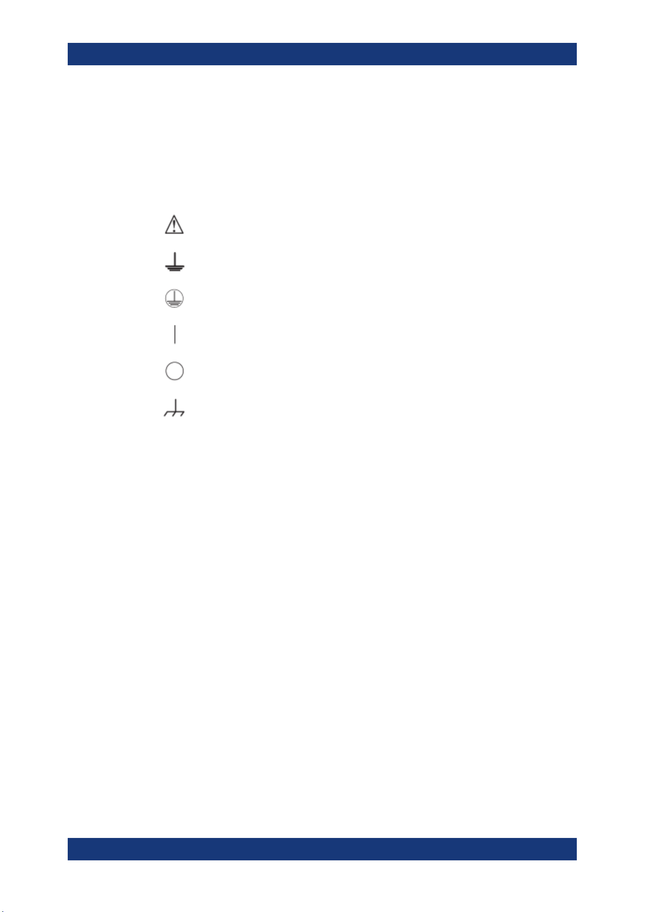
3.1 Symbols
Caution, general danger zone
Ground
PE terminal
ON (supply voltage)
OFF (supply voltage)
Ground terminal
3.2 Ambient Conditions
The allowed operating temperature ranges from +5 °C to +40 °C (pollution category 2).
The maximum relative humidity (without condensation) is at 80 %.
During storage and transport, the temperature must be between -40 °C and +70 °C. In
case of condensation during transportation or storage, the instrument requires approxi-
mately two hours to dry and reach the appropriate temperature prior to operation. The
instrument is designed for use in a clean and dry indoor environment. Do not operate
with high dust and humidity levels, if danger of explosion exists or with aggressive
chemical agents.
Any operating position may be used; however adequate air circulation must be main-
tained. For continuous operation, a horizontal or inclined position (integrated stand) is
preferable.
Specifications with tolerance data apply after a warm-up period of at least 30 minutes
at a temperature of 23 °C (tolerance -3 °C / + 7 °C).
The heat produced inside the instrument is guided to the exterior via temperature-con-
trolled fan. Each channel has multiple temperature sensors which check the heat gen-
eration in the instrument and control the fan speed.
It is necessary to ensure that there is sufficient space around the instrument sides for
heat exchange. If the temperature inside the instrument increases more than the
Ambient Conditions

Important Notes
R&S
®
NGL200/NGM200
13User Manual 1178.8736.02 ─ 09
allowed limit, overtemperature protection is triggered and the affected outputs are
switched off automatically.
Air circulation
Do not obstruct the ventilation holes!
3.3 Measurement Categories
This instrument is designed for supplying power-on circuits that are only indirectly con-
nected to the low voltage mains or not connected at all. The instrument is not intended
for measurements within the measurement categories II, III or IV; the maximum poten-
tial against earth generated by the user must not exceed 250 V peak in this application.
The following information refers solely to user safety. Other aspects, such as the maxi-
mum voltage, are described in the technical data and must also be observed.
The measurement categories refer to transients that are superimposed on the mains
voltage. Transients are short, very fast (steep) current and voltage variations which
may occur periodically and non-periodically. The level of potential transients increases
as the distance to the source of the low voltage installation decreases.
●
Measurement CAT IV: Measurements at the source of the low voltage installations
(e.g. meters)
●
Measurement CAT III: Measurements in building installations (e.g. power distribu-
tion installations, power switches, firmly installed sockets, firmly installed engines
etc.)
●
Measurement CAT II: Measurements on circuits electronically directly connected to
the mains (e.g. household appliances, power tools, etc.)
●
0 (instruments without measured measurement category): Other circuits that are
not connected directly to the mains
3.4 Mains Voltage
The instrument uses 50 Hz / 60 Hz mains voltages ranging from 100 VAC, 115 VAC or
230 VAC (tolerance ± 10 %). Mains voltage must be set correctly by removing the fuse
holder and rotating until the correct voltage appears through the window and reinstal-
ling the fuse holder. The input line fuse is accessible externally. Power socket and fuse
holder form a single unit.
You need to first disconnect the power cord from the connector before you can safely
replace the fuse (as long as the fuse holder is undamaged). Next, the fuse holder must
be pried out using a screwdriver. The starting point is a slot next to the contacts. The
fuse can then be forced out of its mounting and must be replaced with an identical fuse
(see information about the fuse type on the rear panel). The fuse holder is inserted
Mains Voltage
Important Notes
R&S
®
NGL200/NGM200
14User Manual 1178.8736.02 ─ 09
against the spring pressure until it locks into place. The use of mended fuses or short
circuiting the fuse holder is prohibited. Resulting damages are not covered by the war-
ranty.
Safe operation
If the instrument is not in use, it must be switched off at the mains switch for safety rea-
sons.
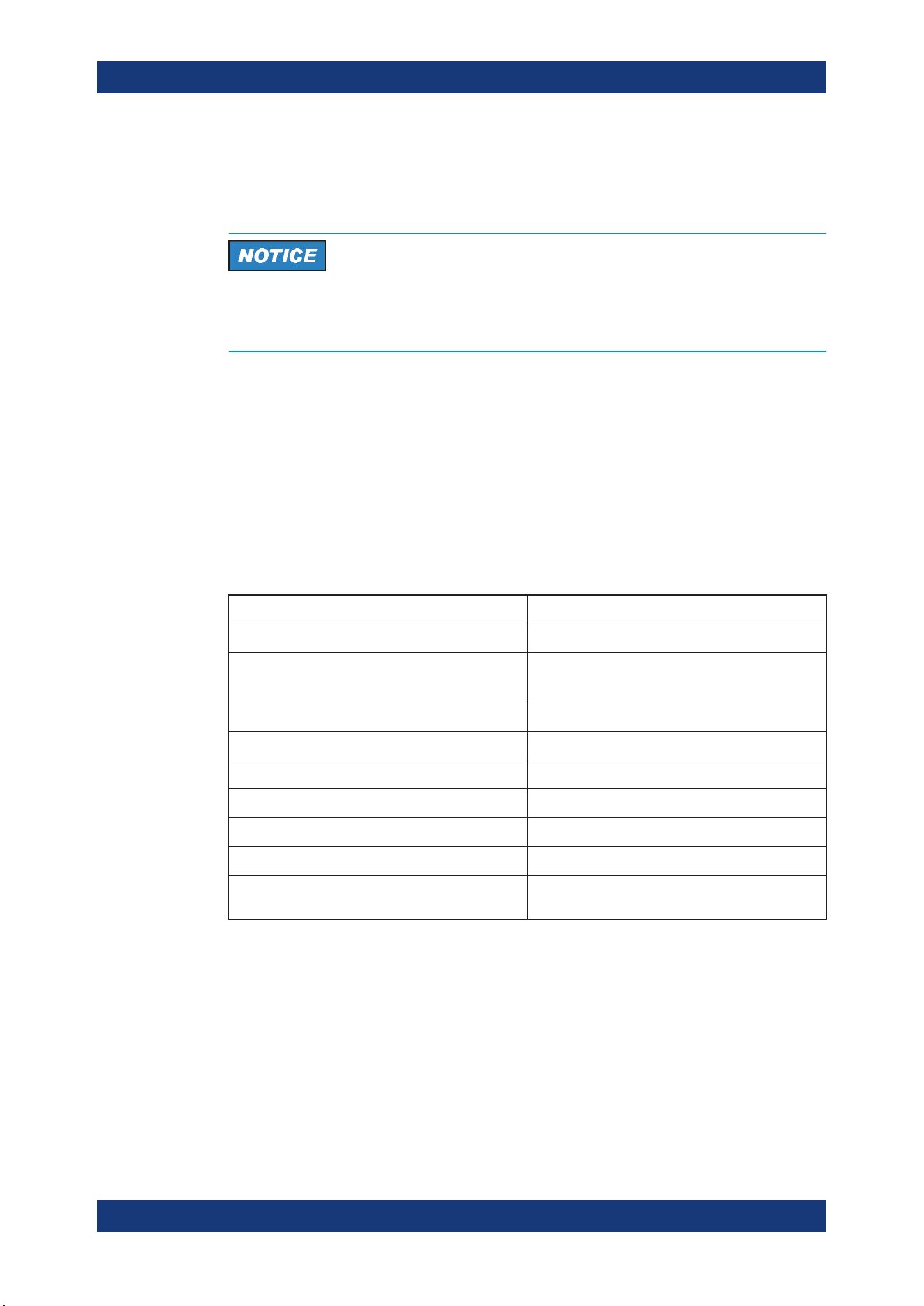
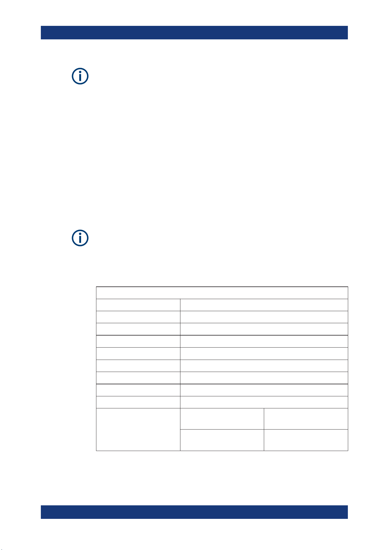
3.5 Limits
The R&S NGL/NGM is equipped with a protective overload feature. The protective
overload feature prevents damage to the instrument and is intended to protect against
a possible electrical shock. The maximum values for the instrument must not be excee-
ded. The protection limits are listed on the front panel of the R&S NGL/NGM to ensure
the safe operation of the instrument.
These protection limits must be adhered to:
Specification Limits
Maximum output voltage 20.05 VDC
Maximum output current 6.01 A (<= 6 V)
3.01 A (> 6 V)
Maximum voltage against earth 250 V peak
Maximum counter-voltage (same polarity) 22 V
Maximum reverse voltage (opposite polarity) 0.5 V
Maximum reverse current sink current 3.01 A
Power supply 100 VAC, 115 VAC or 230 VAC (tolerance ± 10 %)
Frequency 50 Hz / 60 Hz
Maximum power output 120 W (NGL202, NGM202), 60 W (NGL201,
NGM201)
Limits
Getting Started
R&S
®
NGL200/NGM200
15User Manual 1178.8736.02 ─ 09
4 Getting Started
4.1 Putting into Operation
This chapter describes how to set up the R&S NGL/NGM power supply series for the
first time.
Risk of injury due to disregarding safety information
Observe the information on appropriate operating conditions provided in the data sheet
to prevent personal injury or damage to the instrument. Read and observe the basic
safety instructions provided with the instrument, in addition to the safety instructions in
the following sections. In particular:
●
Do not open the instrument casing.
Risk of instrument damage due to inappropriate operating conditions
Specific operating conditions are required to ensure accurate measurements and to
avoid damage to the instrument. Observe the information on appropriate operating
conditions provided in the basic safety instructions and the instrument's data sheet.
Instrument damage caused by electrostatic discharge
Electrostatic discharge (ESD) can damage the electronic components of the instrument
and the device under test (DUT). Electrostatic discharge is most likely to occur when
you connect or disconnect a DUT or test fixture to the instrument's test ports. To pre-
vent electrostatic discharge, use a wrist strap and cord and connect yourself to the
ground, or use a conductive floor mat and heel strap combination.
Risk of radio interference
This instrument is compliant with Class A of CISPR 32. In a residential environment,
this instrument may cause radio interference.
Putting into Operation
Getting Started
R&S
®
NGL200/NGM200
16User Manual 1178.8736.02 ─ 09
Risk of instrument damage during operation
An unsuitable operating site or test setup can cause damage to the instrument and the
connected devices. Ensure the following operating conditions before you switch on the
instrument:
●
The instrument is dry and shows no sign of condensation
●
The instrument is positioned as described in
Chapter 4.1.4.1, "Bench Operation",
on page 19
●
The ambient temperature does not exceed the range specified in the data sheet
●
Signal levels at the input connectors are all within the specified ranges
●
Signal outputs are correctly connected and not overloaded
EMI impact on measurement results
Electromagnetic interference (EMI) may affect the measurement results.
To suppress generated electromagnetic interference (EMI):
●
Use suitable shielded cables of high quality. For example, use double-shielded RF
and LAN cables.
●
Always terminate open cable ends.
●
Note the EMC classification in the data sheet.
4.1.1 Safety
Recommendations on secure operation
The R&S NGL/NGM is designed to operate at local workplaces or in secured networks
(LAN). It should not be accessible from the internet, because of a potential security
risk, e.g. attackers could misuse or damage your device.
Please always install the latest firmware.
It is highly recommended that you work closely with your IT department or system
administrator to ensure compliance with your company policies when connecting devi-
ces to your company's network.
This instrument was built in compliance with DIN EN 61010-1, safety regulations for
electrical instruments, control units and Iaboratory equipment.
It has been tested and shipped from the plant in safe condition. It is also in compliance
with the regulations of the European standard EN 61010-1 and the international stan-
dard IEC 61010-1.
To maintain this condition and ensure safe operation, you must observe all instructions
and warnings given in this user manual. Casing, chassis and all measuring ports are
Putting into Operation

Getting Started
R&S
®
NGL200/NGM200
17User Manual 1178.8736.02 ─ 09
connected to a protective earth conductor. The instrument is designed in compliance
with the regulations of protection class I.
For safety reasons, the instrument may only be operated with authorized safety sock-
ets. The power cable must be plugged in before signal circuits may be connected.
Never use the product if the power cable is damaged. Check regularly if the power
cables are in perfect condition. Choose suitable protective measures and installation
types to ensure that the power cable cannot be damaged and that no harm is caused
by tripping hazards or from electric shock, for instance.
Risk of electric shock
It is prohibited to disconnect the earthed protective connection inside or outside of the
instrument!
If it is assumed that a safe operation is no longer possible, the instrument must be shut
down and secured against any unintended operation.
Safe operation can no longer be assumed when:
●
Instrument shows visible damage
●
Instrument includes loose parts
●
Instrument no longer functions properly
– After an extended period of storage under unfavorable conditions (e.g. out-
doors or in damp rooms)
– After rough handling during transport (e.g. packaging that does not meet the
minimum requirements by post office, railway or forwarding agency)
Exceeding the low voltage protection
Use insulated wires and not bare wires for the terminal connection.
It is assumed that only qualified and trained personnel service the power supplies and
the connected loads.
Before switching on the product, it must be ensured that the nominal voltage setting on
the product matches the nominal voltage of the AC supply network.
4.1.2 Intended Operation
The instrument is intended only for use by personnel familiar with the potential risks of
measuring electrical quantities.
For safety reasons, the instrument may only be connected to properly installed wall
outlets. Separating the ground is prohibited.
The power cable must be inserted before signal circuits may be connected.
Putting into Operation
Getting Started
R&S
®
NGL200/NGM200
18User Manual 1178.8736.02 ─ 09
Use only the power cable included in the delivery package. See "Delivery package"
on page 19.
Before each measurement, measuring cables must be inspected for damage and
replaced if necessary. Damaged or worn components can damage the instrument or
cause injury.
The instrument may be operated only under the operating conditions and in the posi-
tions specified by the manufacturer, without the product's ventilation being obstructed.
If the manufacturer’s specifications are not observed, this can result in electric shock,
fire and/or serious personal injury, and in some cases, death.
Applicable local or national safety regulations and rules for the prevention of accidents
must be observed in all work performed.
The instrument is designed for use in the following sectors: Industrial, residential, busi-
ness and commercial areas and small businesses.
The instrument is designed for indoor use only. Before each measurement, you need
to verify at a known source if the instrument functions properly.
To disconnect from the mains, unplug the IEC socket on the back panel.
See
Table 4-1 for the general data on the instrument specification. For more informa-
tion, see the instrument datasheet (P/N: 5216.1057.32).
Table 4-1: General data on instrument specification
General data
Mains nominal voltage AC 100 V / 115 V / 230 V (±10 %) 50 Hz to 60 Hz
Maximum power consumption 400 W
Mains fuses 2 x IEC T4.0H 250 V
Operating temperature range +5 °C to +40 °C
Storage temperature range -20 °C to +70 °C
Humidity noncondensing 5 % to 95 %
Display TFT 5" 800 pixels x 480 pixels WVGA Touch
Rack installation R&S HZN96 rack adapter 2U (P/N: 3638.7813.02)
Dimensions (W x H x D) 222 mm x 97 mm x 436 mm (8.74" x 3.82" x 17.17")
Weight R&S NGL201
R&S NGM201
7.1 kg (15.65 lb)
7.2 kg (15.87 lb)
R&S NGL202
R&S NGM202
7.3 kg (16.09 lb)
7.4 kg (16.31 lb)
Putting into Operation
Getting Started
R&S
®
NGL200/NGM200
19User Manual 1178.8736.02 ─ 09
4.1.3 Unpacking and Checking the Instrument
Unpack the R&S NGL/NGM power supply carefully and check the content of the pack-
age.
●
Check the equipment for completeness using the delivery note and package con-
tents list for the various items.
●
Check the instrument for any damage and loose parts. If there is any damage,
immediately contact the carrier who delivered the instrument.
Packing material
Retain the original packing material. If the instrument needs to be transported or ship-
ped later, you can use the material to protect the control elements and connectors.
Risk of damage during transportation and shipment
Insufficient protection against mechanical and electrostatic effects during transportation
and shipment can damage the instrument.
●
Always ensure that sufficient mechanical and electrostatic protections are provided
●
When shipping an instrument, the original packaging should be used. If you do not
have the original packaging, use sufficient padding to prevent the instrument from
moving around inside the box. Pack the instrument in antistatic wrap to protect it
from electrostatic charging
●
Secure the instrument to prevent any movement and other mechanical effects dur-
ing transportation
Delivery package
The package contents contain the following items:
●
R&S NGL power supply or R&S NGM power supply
●
Four power cables
●
One printed Getting Started manual
●
One document folder containing a printed Basic Safety Instructions guide
4.1.4 Setting Up the Instrument
The R&S NGL/NGM is designed for benchtop and rackmount operation.
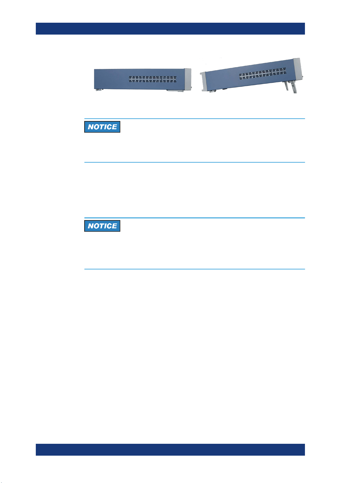
4.1.4.1 Bench Operation
On a benchtop, the R&S NGL/NGM power supply can either lie flat or stand on its feet.
As shown in
Figure 4-1, feet on the bottom can be folded out to set the instrument in
an inclined position.
Putting into Operation
Getting Started
R&S
®
NGL200/NGM200
20User Manual 1178.8736.02 ─ 09
Figure 4-1: Operating positions
Positioning of instrument
The instrument must be positioned in a manner that allows you to disconnect the unit
from the mains at any time and without restrictions.
4.1.4.2 Rack Mounting
The instrument can be installed in a 19" rack using the rack adapter R&S HZN96 (P/N
3638.7813.02). Proceed according to the installation instructions supplied with the rack
adapter.
Ambient temperature
Place the R&S NGL/NGM power supply in an area where the ambient temperature is
within +5 °C to +40 °C. The R&S NGL/NGM power supply is fan-cooled and must be
installed with sufficient space along the sides to ensure free flow of air.
4.2 Instrument Tour
This chapter provides an overview of all the controls available in the R&S NGL/NGM
models and steps to switch on the instrument for the first time.
●
Overview of Controls...............................................................................................20
●
Switching On the Instrument...................................................................................24
4.2.1 Overview of Controls
4.2.1.1 Front Panel
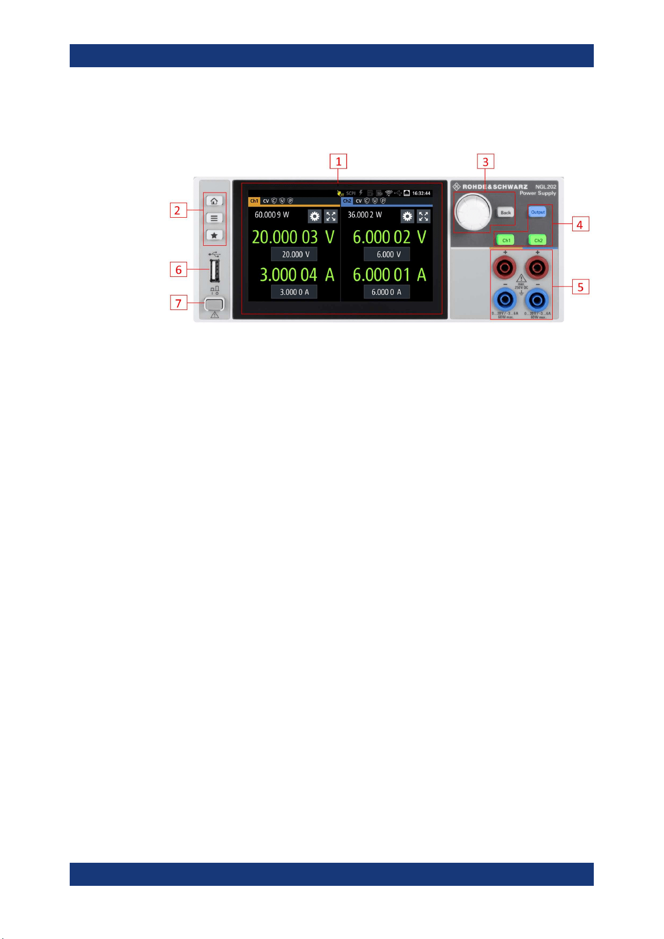
The front panel of the R&S NGL/NGM is as shown in Figure 4-2. The function keys and
navigation controls are located beside the display. The various connectors are located
at the right side of the display.
Instrument Tour
Getting Started
R&S
®
NGL200/NGM200
21User Manual 1178.8736.02 ─ 09
The R&S NGL/NGM has one output channel for NGL201, NGM201 models and two
output channels for NGL202, NGM202 models.
Figure 4-2: Front panel of R&S
NGL/NGM with 2 channels
1 = Display with touch screen
2 = Menu control keys
3 = Rotary knob and back key
4 = Output and channel keys
5 = Output terminals (one channel with sense for NGL201, NGM201; two channels for NGL202, NGM202)
6 = USB connector
7 = Power key
Display (1)
The display is a color TFT touch screen. Depending on the instrument model, up to two
channels are shown on the display. The respective measurement settings and func-
tions are displayed in the individual channel display area. There is a status bar in the
device level and channel level, showing the device operating mode and respective
channel settings of the instrument.
For a detailed description on-screen layout, see
Chapter 5.1, "Display Overview",
on page 29.
Menu control keys (2)
The menu control keys allow you to access the home window, device/channel menu
window and user key in the instrument.
For a detailed description on menu control keys, see
Chapter 5.3.1, "Menu Controls",
on page 37.
Rotary knob and back key (3)
The rotary knob and back key are used for menu navigation and value adjustment in
the instrument.
For a detailed description on rotary knob and back key, see section Chapter 5.3.2,
"Navigation Controls"
, on page 40.
Instrument Tour
Getting Started
R&S
®
NGL200/NGM200
22User Manual 1178.8736.02 ─ 09
Output and channel keys (4)
The channel key allows you to select the power supply channel to source or sink
power. The output key allows you to enable or disable the output power on the channel
key.
Refer to datasheet for the channel voltage/current limits in the source and sink mode.
Output terminals (5)
Depending on the instrument type, one or two output channels are available to source
or sink power.
Both instrument models are equipped with 4 terminals. The NGL201, NGM201 models
provide both the output plus the sense connectors at the front panel while the NGL202,
NGM202 models provide only output terminals for both channels.
USB connector (6)
The USB connector is a Type-A connector. You can connect a USB flash drive to this
connector to perform a firmware update, store logging data or screen shots.
Power key (7)
The [Power] key switches the instrument on and off.
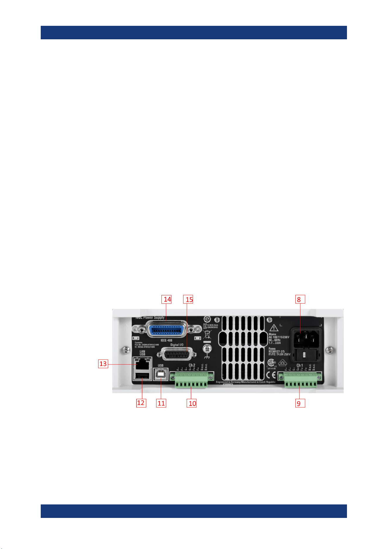
4.2.1.2 Rear Panel
Figure 4-3 shows the rear panel of the R&S NGL/NGM with its connectors.
Figure 4-3: Rear panel of R&S
NGL/NGM with 2 channels
8 = AC inlet with fuse holder and voltage selector
9 = Channel 1 rear panel connector for NGL202, NGM202 models. The two D.n.c. labels for NGM201 are
labeled as DVM+ and DVM-
10 = Channel 2 rear panel connector for NGL202, NGM202 models. The two D.n.c. labels for NGM202 are
labeled as DVM+ and DVM-
11 = USB connector (device)
12 = USB connector (host)
Instrument Tour
Getting Started
R&S
®
NGL200/NGM200
23User Manual 1178.8736.02 ─ 09
13 = Ethernet (LAN) connector
14 = Optional IEEE-488 (GPIB) interface
15 = Digital I/O connector
AC inlet with fuse holder and voltage selector (8)
Main supply cord
Do not use detachable mains supply cord with inadequate rating.
The power cable must be plugged in before signal circuits can be connected. Do not
use the product if the power cable is damaged. See Chapter 4.2.2, "Switching On the
Instrument"
, on page 24 for more information.
The built-in voltage selector selects the mains voltage between 100 V, 115 V and 230
V. All voltage settings are using the same fuse rating.
Channel connectors (9, 10)
Output terminals
Either the output terminals at the front panel or those at the back panel can be used.
Using both terminals at the same time can cause instrument malfunction.
Digital voltmeter (DVM)
The DVM+ and DVM- pins on the channel connector are available only with R&S NGM
power supply series equipped with option R&S NGM-K104 (P/N: 3643.9927.02).
The channel connectors contain both output ("F+", "F-") and sense ("S+", "S-") connec-
tions. Connector for "Ch2" is only available in the NGL202, NGM202 models.
USB connectors (11, 12)
The USB host connector (Type-A) can be used for mass storage devices or an external
mouse like the USB connector at the front panel.
The USB device connector is a Type-B connector for remote control operation.
Ethernet connector (13)
10/100 Ethernet port for remote control operation via the local area network.
For a detailed description on the connection setup, see
Chapter 6.16.1.1, "LAN Con-
nection"
, on page 85.
Option IEEE-488 (GPIB) interface (14)
An IEEE-488 (GPIB) interface can be ordered (NGL-B105 or NGM-B105). This inter-
face is not user installable.
Instrument Tour
Getting Started
R&S
®
NGL200/NGM200
24User Manual 1178.8736.02 ─ 09
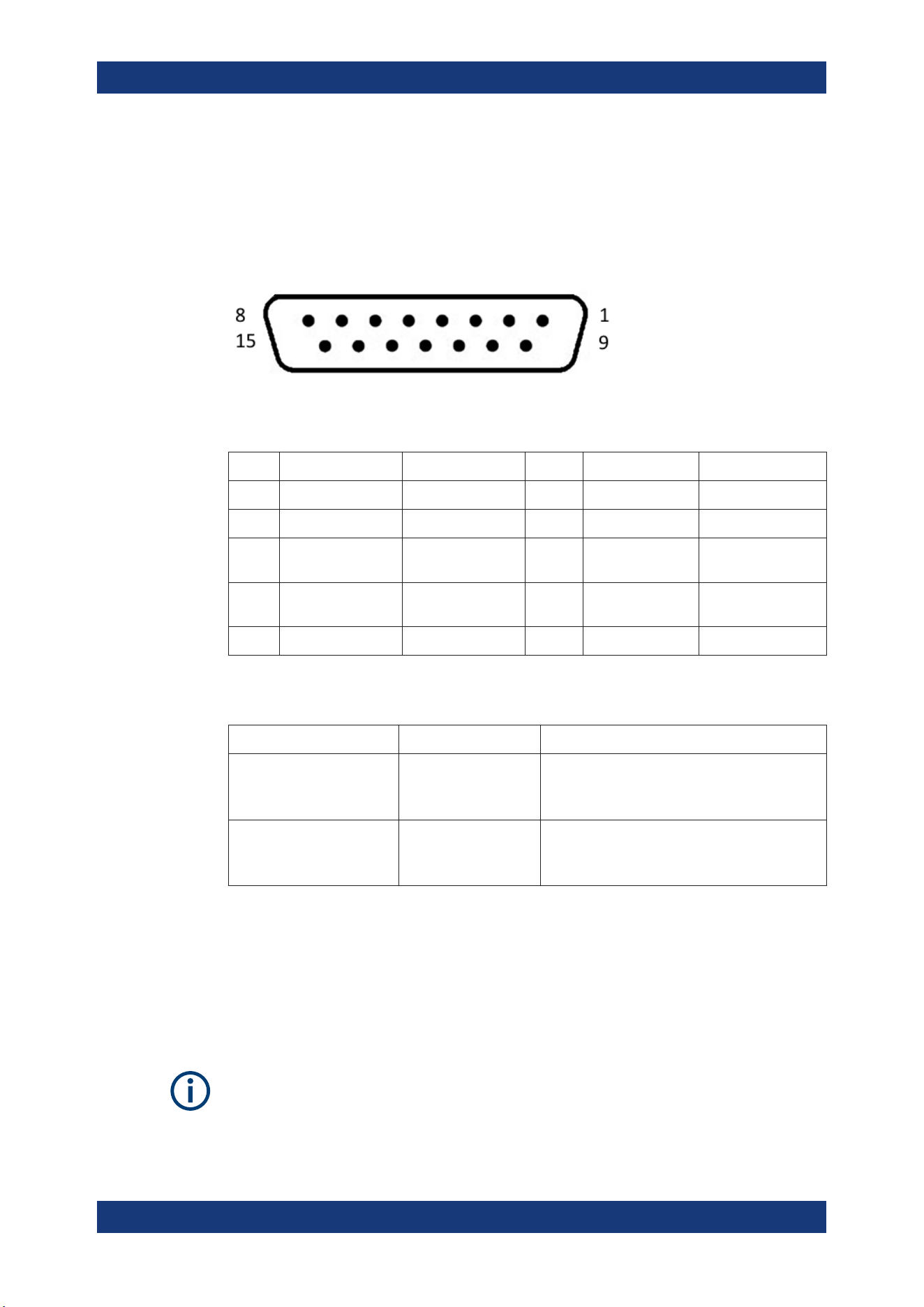
Digital I/O connector (15)
The Digital I/O option (R&S NGL-K103 or R&S NGM-K103) must be installed for this
function to be available in the instrument.
The specified voltages are 0 V to 24 V for all output pins and 0 V to 15 V for all input
pins.
Figure 4-4: Digital I/O connector (female socket front view)
Table 4-2: Digital I/O pin layout
Pin Signal Direction Pin Signal Direction
1 *Inhibit Ch1 IN 9 *Inhibit Ch2 IN
2 Ext. Trigger Ch1 IN 10 Ext. Trigger Ch2 IN
3 Digital In1 IN 11 Digital Output
Fault
OUT
4 Digital Output Out1 OUT 12 Digital Output
Out2
OUT
5 - 8 Gnd - 13 - 15 Gnd -
* The inhibit signals can be used to turn off the outputs by a digital hardware signal.
Table 4-3: Inhibit signals
Signal name Pin Descriptions
Inhibit Ch1 Pin 1 of Digital I/O con-
nector
If the inhibit signal goes active, channel 1 output
is turned off.
The inhibit signal is low active (inverted logic).
Inhibit Ch2 Pin 9 of Digital I/O con-
nector
If the inhibit signal goes active, channel 2 output
is turned off
The inhibit signal is low active (inverted logic).
4.2.2 Switching On the Instrument
Before switching on the instrument, check that all the instructions in the “Basic Safety
Instruction” brochure and safety measures in previous sections are observed. Also,
check if the value on the voltage selector corresponds to the mains voltage (100 V, 115
V or 230 V).
Fuse rating
The R&S NGL/NGM uses the same fuse ratings for all mains voltages.
Instrument Tour

Getting Started
R&S
®
NGL200/NGM200
25User Manual 1178.8736.02 ─ 09
To change power fuse / mains voltage setting:
1. Peel off the yellow label sticker on the AC inlet.
2. Release the latch of the fuse holder which is located at both side of the socket and
pull it out.
3. Pull out the removable part of the fuse holder.
4. Turn this removable part until the correct voltage label (100, 115 or 230) is dis-
played in the window of the holder.
5. Return the fuse holder to its position in the panel.
To switch on instrument:
1. Connect the power cable to the AC power connector on the rear panel of the
R&S NGL/NGM.
2. Connect the power cable to the socket outlet.
3. Press [Power] key on the front panel.
The instrument performs a system check, boots the operating system, and starts
the R&S NGL/NGM firmware.
By default, all output channels are turned off when the instrument is switched on to
prevent connected loads from being damaged unintentionally.
During startup, the R&S NGL/NGM is loaded with the last saved instrument settings
from internal memory. See
Chapter 6.15, "Store and Recall ", on page 81.
To switch off instrument:
1. Press [Power] key.
All current settings are saved to internal memory and the firmware shuts down.
2. Disconnect the AC power cable from the instrument.
4.3 Trying Out the Instrument
This chapter describes some basic functions that you can perform with the R&S NGL/
NGM.
Trying Out the Instrument

Getting Started
R&S
®
NGL200/NGM200
26User Manual 1178.8736.02 ─ 09
Source and sink current
The R&S NGL/NGM power supply series are 2 quadrant power supplies which may
both source and sink current. When the voltage across the output terminal exceeds the
set voltage, current flows into the instrument. The default behavior "Auto" can be con-
figured in output menu, see
Chapter 6.2.3.4, "Output Mode", on page 51.
On the display, sink mode is shown as negative current. See also "CR mode"
on page 26.
4.3.1 Setting the Output Voltage and Current
1. Press [Home] key.
The R&S NGL/NGM displays the home window.
2. Select voltage or current parameter in the home window.
The R&S NGL/NGM displays an on-screen keypad to set the value.
3. Enter the required value.
4. Confirm value with the unit key (V/mV or A/mA).
See
"Source and sink current" on page 26 for more information on the operating
modes supported in different models.
4.3.2 Activating the Channels Output
The output voltages can be switched on or off regardless of the instrument's operating
mode.
To switch on or off channel output.
1. For the two-channel models, select desired channel key ([Ch1] or [Ch2]) on the
front panel.
2. Press [Output] key.
The R&S NGL/NGM outputs the set voltage level on the output channel terminal.
Depending on the operating mode which the channels are operated in, the following
are observed:
CR mode
CR mode is a special case of sink mode in which the instrument behaves like a con-
stant resistor. Only in this mode, the respective channel keys and display font color in
the home window turns cyan.
In "normal" sink mode, the colors are the same as in source mode: green if the current
flowing into the R&S NGL/NGM is below the set current and red if the current is limited
to the set value. The only visible indication of sink mode is the change of sign of the
current readout to "Minus".
Trying Out the Instrument
Getting Started
R&S
®
NGL200/NGM200
27User Manual 1178.8736.02 ─ 09
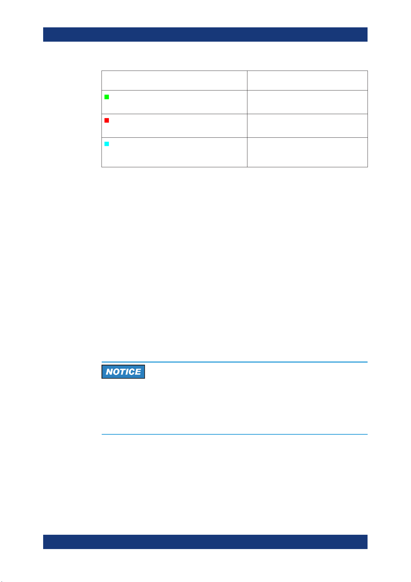
Color illuminated on front panel keys and display
font color of voltage and current in home window
Operating mode
Green
Constant voltage mode (CV)
Red
Constant current mode (CC)
Cyan
Constant resistance mode (CR)
Note: Instrument is operated in sink mode and
"Constant Resistance" is activated.
Also, the operating symbol mode (CV, CC or CR) is displayed at the channel status bar
of the respective channel.
4.4 Maintenance and Support
4.4.1 Maintenance
Regular maintenance improves the life span of the instrument, the following chapter
provides information on instrument maintenance.
Cleaning
Before cleaning the instrument, ensure that it has been switched off and the power
cable is disconnected.
Clean the outer case of the instrument at regular intervals, using a soft, lint-free dust
cloth.
Instrument damage caused by cleaning agents
Use a dry, lint-free cloth to clean the product. When cleaning, keep in mind that the
casing is not waterproof. Do not use any liquids for cleaning.
Cleaning agents, solvents (thinners, acetone), acids and bases can damage the front
panel labeling, plastic parts and display.
The display may only be cleaned with an appropriate glass cleaner. Rub the display
with a dry, clean and lint-free cloth. Do not allow cleaning fluid to enter the instrument.
Maintenance and Support

Getting Started
R&S
®
NGL200/NGM200
28User Manual 1178.8736.02 ─ 09
4.4.2 Contacting Customer Support
Technical support – where and when you need it
For quick, expert help with any Rohde & Schwarz product, contact our customer sup-
port center. A team of highly qualified engineers provides support and works with you
to find a solution to your query on any aspect of the operation, programming or applica-
tions of Rohde & Schwarz products.
Contact information
Contact our customer support center at
www.rohde-schwarz.com/support, or follow this
QR code:
Figure 4-5: QR code to the Rohde
&
Schwarz support page
Maintenance and Support
Operating Basics
R&S
®
NGL200/NGM200
29User Manual 1178.8736.02 ─ 09
5 Operating Basics
5.1 Display Overview
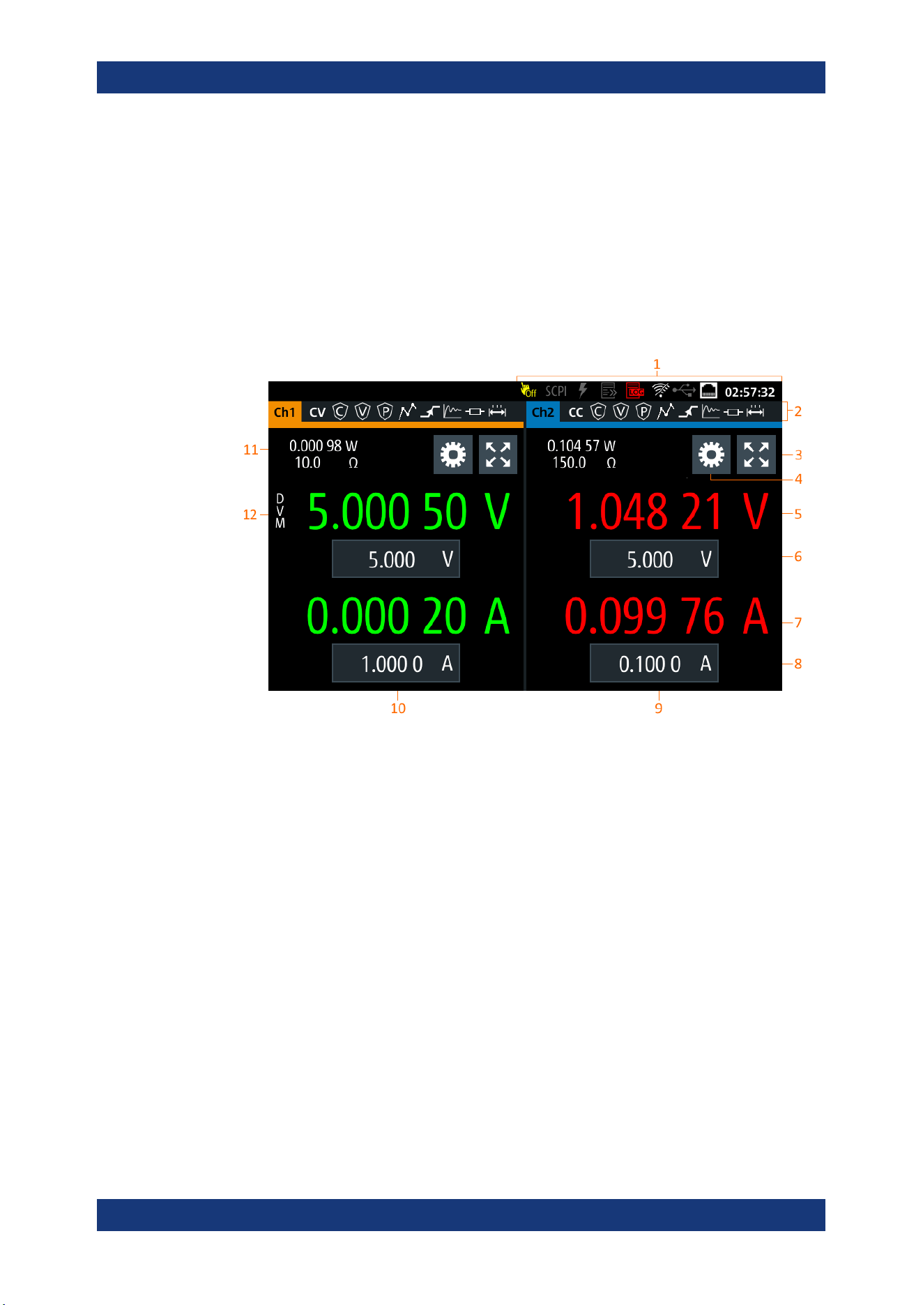
The following displays the home window of R&S NGL/NGM. It shows the output volt-
age and current level, status bar information and control settings of the instrument.
Figure 5-1: Home window of R&S
NGL/NGM with 2 channels
1 = Device status bar
2 = Channel status bar
3 = "Expand/Collapse" channel button
4 = "Settings" button
5 = Measured output voltage
6 = Set output voltage
7 = Measured output current
8 = Set output current limit
9 = Channel display area of Ch2
10 = Channel display area of Ch1
11 = Measured output power and source output resistance/emulated internal impedance
12 =
DVM function (available only with R&S NGM power supply series)
5.1.1 Status Bar Information
There are two types of status bar. One shows device status information and the other
shows the individual channel status information.
Display Overview
Operating Basics
R&S
®
NGL200/NGM200
30User Manual 1178.8736.02 ─ 09
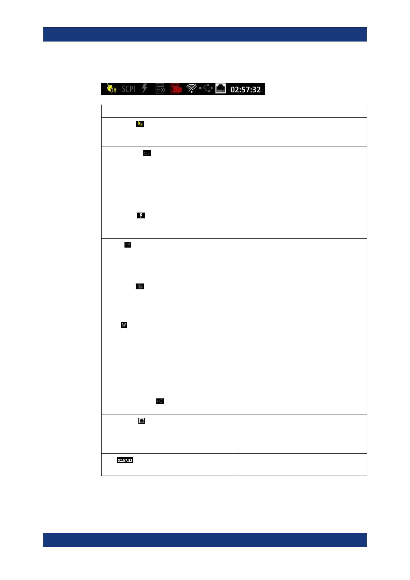
Device status bar
Function Description
Touchscreen
If touch input is disabled, the icon is displayed and
highlighted in yellow.
See Chapter 5.3.1.3, "User Key", on page 40.
SCPI command
If a SCPI command is received successfully, the
icon blinks once in white.
If an error is in the SCPI error queue, the icon is
highlighted in red.
If no activity, icon is displayed in gray.
See Chapter 7, "Remote Control Commands",
on page 96.
Trigger event
Icon blinks once in white when a trigger event
occurs.
See Figure 6-18.
Fast log
Fast logging is only visible with NGM models.
If active, icon is highlighted in white.
If disabled, icon is highlighted in gray.
See Chapter 6.11, "FastLog", on page 75.
Data logging
If data logging is present, the icon is highlighted in
white.
If an error is present, the icon is highlighted in red.
See Chapter 6.10, "Data Logging", on page 73.
WLAN
Only visible if software option Wireless LAN is
active.
If connection is present, the icon is highlighted in
white. If both WLAN and LAN connection are pres-
ent, the icon is highlighted with a line cross over.
If no connection or WLAN is disabled, the icon is
highlighted in gray.
See Chapter 6.16.1.2, "Wireless LAN Connection",
on page 87.
USB device interface
If a host command is received in USB interface, the
icon is highlighted in white.
LAN interface
If connected, the icon is highlighted in white.
If no connection or an error is present in connection,
the icon is highlighted in red.
See Chapter 6.16, "Interfaces", on page 83.
Time
Time displays in hh:mm:ss format.
See Chapter 6.17.4, "Date and Time", on page 93.
Display Overview
Operating Basics
R&S
®
NGL200/NGM200
31User Manual 1178.8736.02 ─ 09
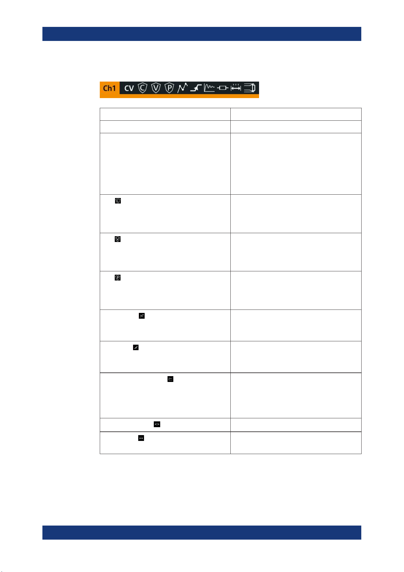
Channel status bar
Function Description
Channel number Channel number indication.
Operation mode The R&S NGL/NGM has three operating modes:
●
CV: Constant voltage mode
●
CC: Constant current mode
●
CR: Constant resistance mode. The
R&S NGL/NGM goes into this mode when
operates in sink mode and the "Constant
Resistance" mode is activated.
See
Chapter 5.5, "Operation Modes", on page 42.
OCP
If enabled, the icon is highlighted in white.
If triggered, the icon blinks.
See Chapter 6.5.1, "Overcurrent Protection (OCP)",
on page 58.
OVP
If enabled, the icon is highlighted in white.
If triggered, the icon blinks.
See Chapter 6.5.2, "Overvoltage Protection (OVP)",
on page 59.
OPP
If enabled, the icon is highlighted in white.
If triggered, the icon blinks.
See Chapter 6.5.3, "Overpower Protection (OPP)",
on page 60.
Arbitrary mode
If enabled, the icon is highlighted in white.
If active, the icon blinks.
See Chapter 6.7.1, "Arbitrary", on page 67.
Ramp mode
If enabled, the icon is highlighted in white.
If active, the icon blinks.
See Chapter 6.7.2, "Ramp", on page 70.
"Fast Transient Response"
If enabled, the icon is highlighted in white.
The time taken for voltage recovery (<=20 mV)
switches between 30 µs and 100 µs.
See
Chapter 6.2.2, "Fast Transient Response",
on page 47.
"Internal Impedance"
If enabled, the icon is highlighted in white.
"Safety Limits"
If enabled, the icon is highlighted in white.
See Chapter 6.5.4, "Safety Limits", on page 61.
Display Overview
Operating Basics
R&S
®
NGL200/NGM200
32User Manual 1178.8736.02 ─ 09
Function Description
"Output Delay"
If enabled, the icon is highlighted in white.
The delay is the time between activation of the out-
put and applying voltage to the output.
See Chapter 6.2.3, "Output", on page 48.
Sense connection
If sense connection is detected, the icon is highligh-
ted in white.
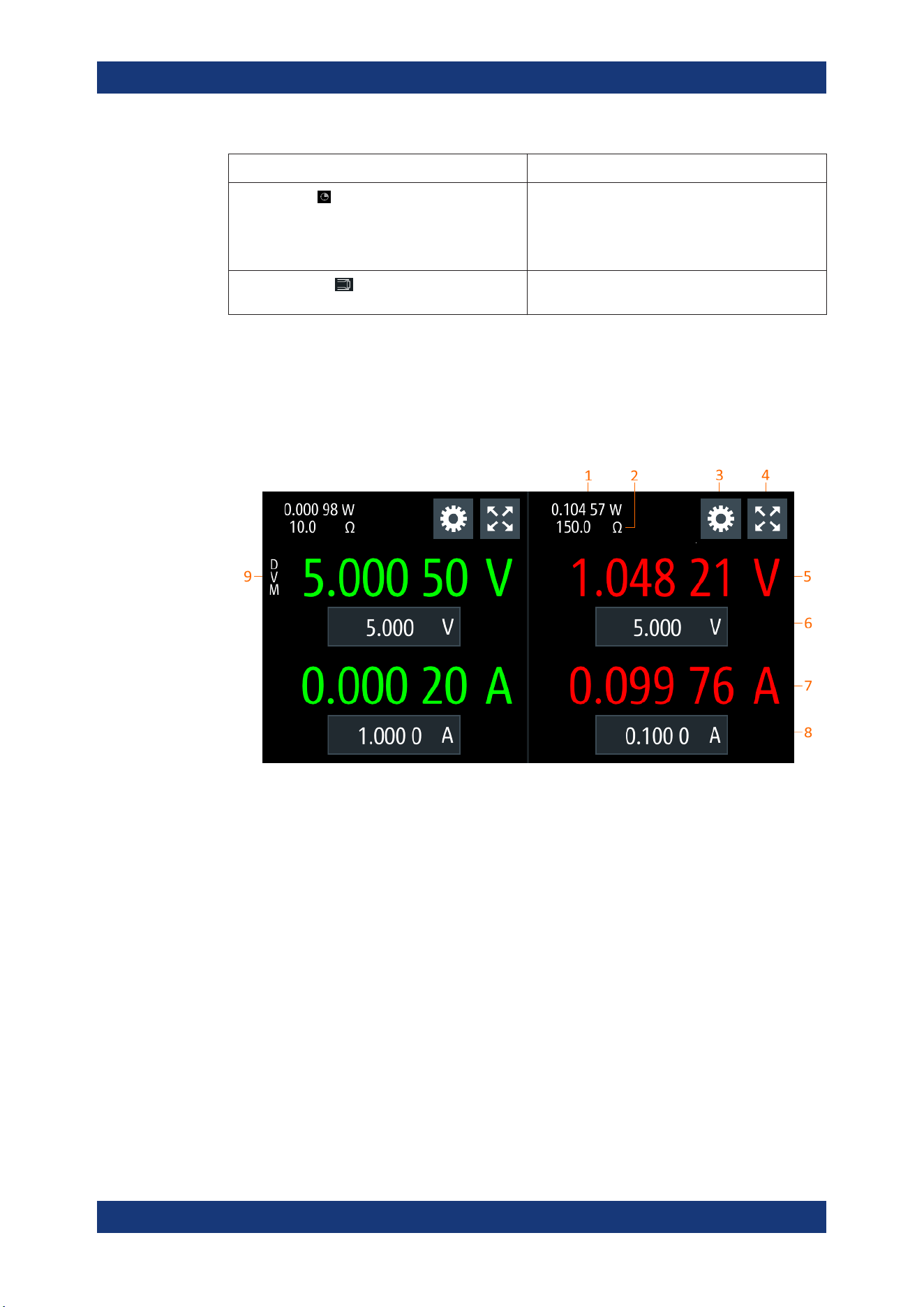
5.1.2 Channel Display Area
The R&S NGL/NGM displays two channels display area (Ch1, Ch2) for NGL202,
NGM202 and a single channel display area (Ch1) for NGL201, NGM201. The respec-
tive channel settings and functions are displayed for each channel.
Figure 5-2: Channel display area for 2-channel model
1 = Output power displays in watt
2 = Source output resistance/emulated internal impedance displays in ohms
3 = "Settings" button opens instrument device/channel menu window. Long-press on the button opens the
graphical view window for measurements
4 = "Expand/Collapse" button toggles between home window and channel overview window
5 = Output voltage displays in volt with display resolution of five decimal points
6 = Set voltage level with level limit defined in Safety Limits
7 = Output current displays in ampere with display resolution of five decimal points
8 = Set current level with level limit defined in Safety Limits
9 = DVM function (available only with R&S NGM power supply series)
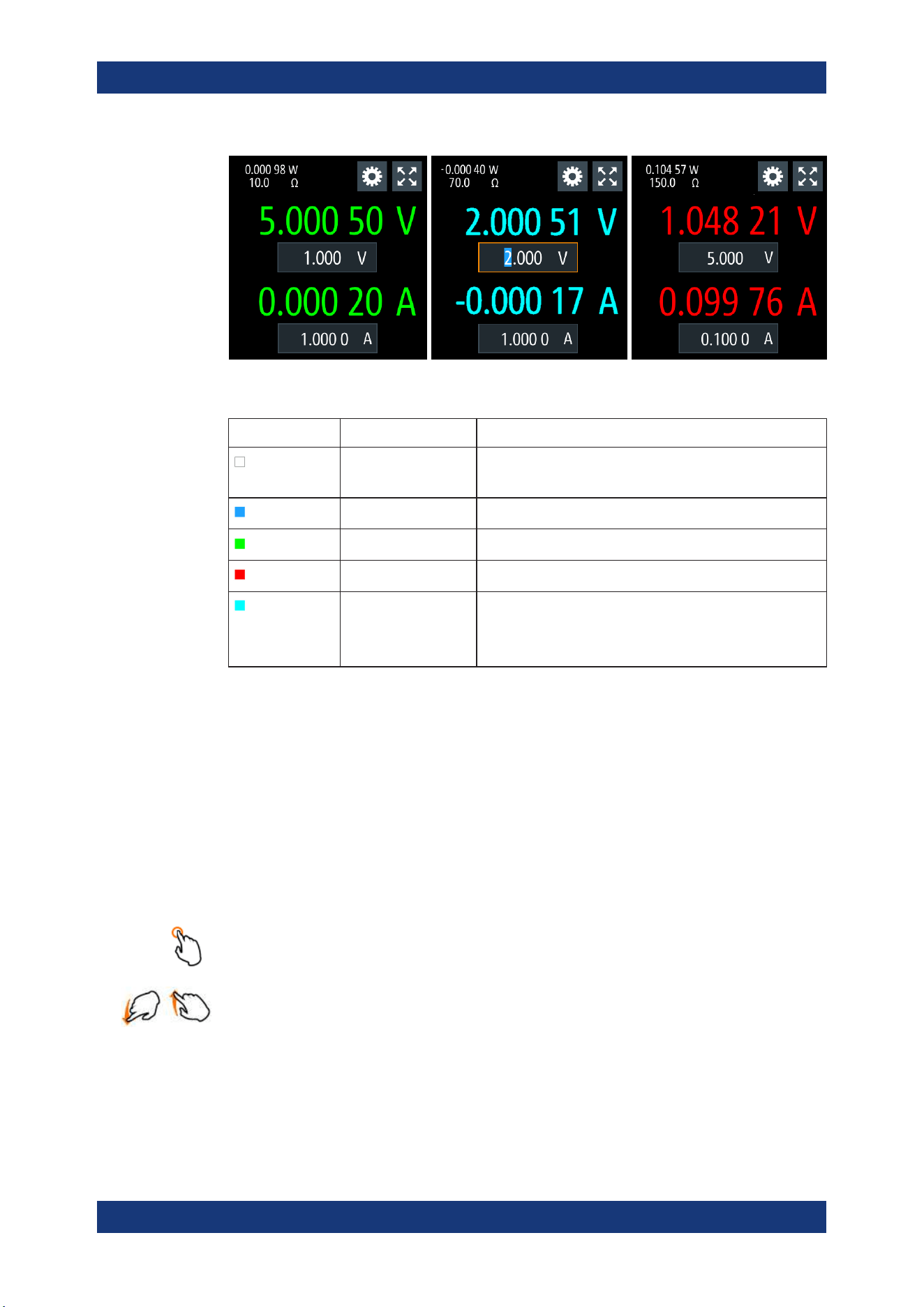
Operating mode
Different font colors on the screen are used to differentiate the various output status
and operating conditions of the instrument. It is easy to know and confirm the different
output status and operating conditions of the instrument by looking at the colors.
Display Overview
Operating Basics
R&S
®
NGL200/NGM200
33User Manual 1178.8736.02 ─ 09
Figure 5-3: Color coding of difference operating conditions
Color Operating mode Description
DVM mode Available only with NGM models.
Display DVM measurement.
Editing mode A solid blue cursor is shown when an item is selected.
CV mode Active outputs are operated in a constant voltage mode.
CC mode Active outputs are operated in a constant current mode.
CR mode Active outputs are operated in a constant resistance mode.
This condition occurs if the set voltage is below the voltage
applied externally at the output connectors (sink mode) and
constant resistor is switched on in channel menu.
5.2 Using the Touchscreen
The R&S NGL/NGM provides a touch-sensitive screen. Touch can be disabled (see
Chapter 6.8, "User Key", on page 71) in the instrument settings. The following illus-
trates the touchscreen gestures and highlight the different touchscreen features that
can be performed on the instrument.
5.2.1 Using Gestures
Tap
Tap on the screen to select or toggle the value.
Swipe up and down
Swipe up to scroll down, swipe down to scroll up in the menu.
5.2.2 Accessing Functionality in the Home Window
The following illustrates various ways of accessing functions in the home window.
Using the Touchscreen
Operating Basics
R&S
®
NGL200/NGM200
34User Manual 1178.8736.02 ─ 09
5.2.2.1 Settings Button
The "Settings" button navigates to the device/channel menu window where you can set
device or individual channel settings on the instrument.
Long-press on the "Settings" button brings you to the
graphical view window for mea-
surements. For more information, see
Chapter 6.13, "Graphical View Window",
on page 78.
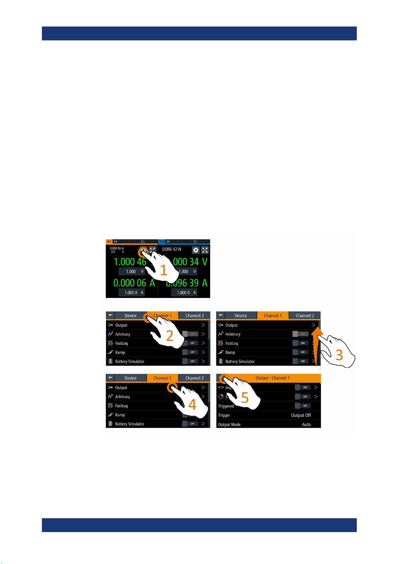
1. Select the "Settings" button.
The R&S NGL/NGM displays device/channel menu window.
2. Select "Device" or respective channel tab ("Channel 1" or "Channel 2") to open the
menu.
3. Swipe up or down for the available items in the menu.
4. Select the required items to configure the settings.
5. Select the back arrow key or press [Back] key to close the menu.
Figure 5-4: Navigation on home window > device/channel menu window
Using the Touchscreen
Operating Basics
R&S
®
NGL200/NGM200
35User Manual 1178.8736.02 ─ 09
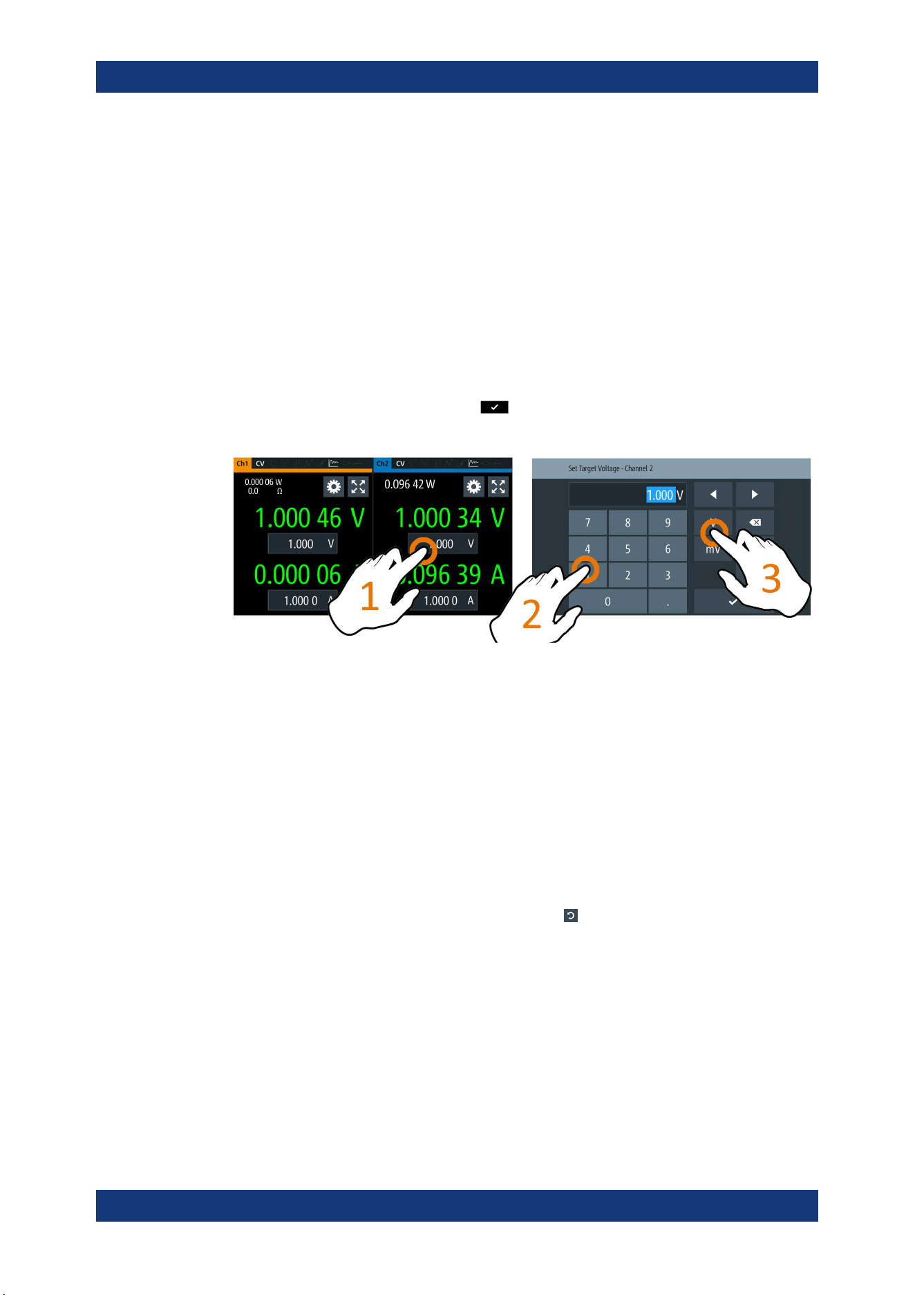
5.2.2.2 Voltage and Current Inputs
You can directly change the voltage and current level in the respective channel display
area.
1. Select the voltage or current field in the channel display area to set value.
The R&S NGL/NGM displays the on-screen keypad to enter value.
2. Set the required value.
See
Chapter 5.2.3, "Input Data", on page 36.
Note: The value is set within the value configured in the "Safety Limits" dialog.
3. Confirm value by selecting a unit key.
Alternatively, select the enter key
to confirm your value.
Figure 5-5: Set voltage and current in home window
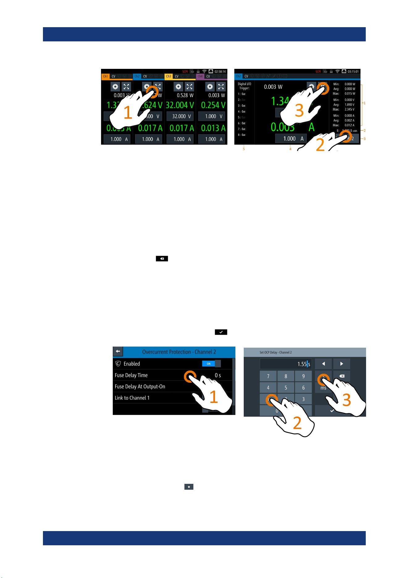
5.2.2.3 Expand/Collapse Button
You can expand the selected channel window by using the "Expand/Collapse" button.
The "Expand/Collapse" icon changed when toggled.
1. Select the "Expand/Collapse" button.
The R&S NGL/NGM expands the selected channel to a full screen displaying the
statistics ("Min", "Avg" and "Max" values of power, voltage and current readings,
energy calculation and count of samples recorded).
2.
To reset the statistics, select the reset button,
.
The statistics values are reset to zero.
Note: The statistics provides valid data for up to 365 days of continuous operation,
after which the statistics will be reset to zero.
3. Select the "Expand/Collapse" button to revert to the home window.
Using the Touchscreen
Operating Basics
R&S
®
NGL200/NGM200
36User Manual 1178.8736.02 ─ 09
Figure 5-6: Display of channel overview window
1 = Minimum, maximum and average values for power, voltage and current
2 = Calculation of energy result
3 = Count of samples collected
4 = Channel display area of selected channel
5 = Digital I/O trigger of selected channel
5.2.3 Input Data
The R&S NGL/NGM provides an on-screen keypad for you to enter numerical values.
Use the back key
on the on-screen keypad to cancel input of the numerical
entries.
1. Select a menu item to enter the numeric value.
The R&S NGL/NGM displays the on-screen keypad.
2. Enter the required value.
3. Confirm value with the unit key.
Alternatively, select the enter key
to confirm your value.
Figure 5-7: Enter numerical value and unit
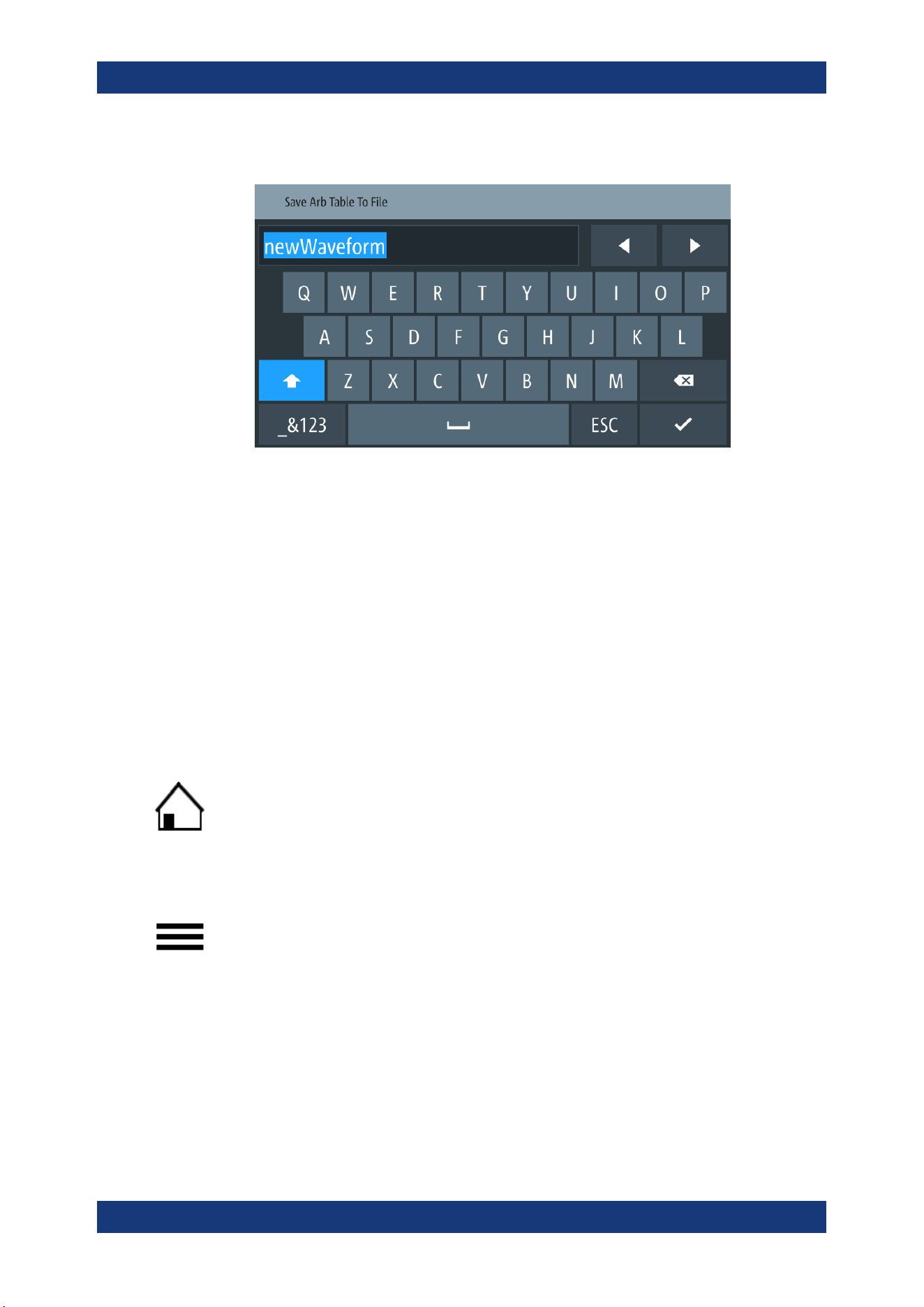
For alphanumeric input, the on-screen keypad works the same way.
1.
Select the "Caps Lock"
key to switch between capital letters and small letters.
The "Caps Lock" key is highlighted in blue.
Using the Touchscreen
Operating Basics
R&S
®
NGL200/NGM200
37User Manual 1178.8736.02 ─ 09
2. Select "&123" or "ABC" key to switch between alphabet and numeric input data.
Figure 5-8: Alphanumeric input data
5.3 Front Panel Keys
For an overview of the front panel keys, see Figure 4-2.
5.3.1 Menu Controls
The menu controls keys provide navigation on the available menus in the instrument.
5.3.1.1 Home Key
The [Home] key navigates to the instrument home window. See the display of the
home window in
Figure 5-1.
5.3.1.2 Settings Key
The [Settings] key navigates to the device/channel menu window which consists of the
"Device" menu and up to two channels ("Channel 1", "Channel 2") menu.
Long-press on the [Settings] key also navigates to the graphical view window. For
more information, see
Chapter 6.13, "Graphical View Window", on page 78.
Device menu
The "Device" menu provides access to general instrument settings, file arrangement
and user key configuration. You can also obtain the instrument information via the
menu.
1. Press [Home] key.
Front Panel Keys
Operating Basics
R&S
®
NGL200/NGM200
38User Manual 1178.8736.02 ─ 09
The R&S NGL/NGM displays the home window.
2. Select the "Settings" button on the required channel display area.
Alternatively, press [Settings] key.
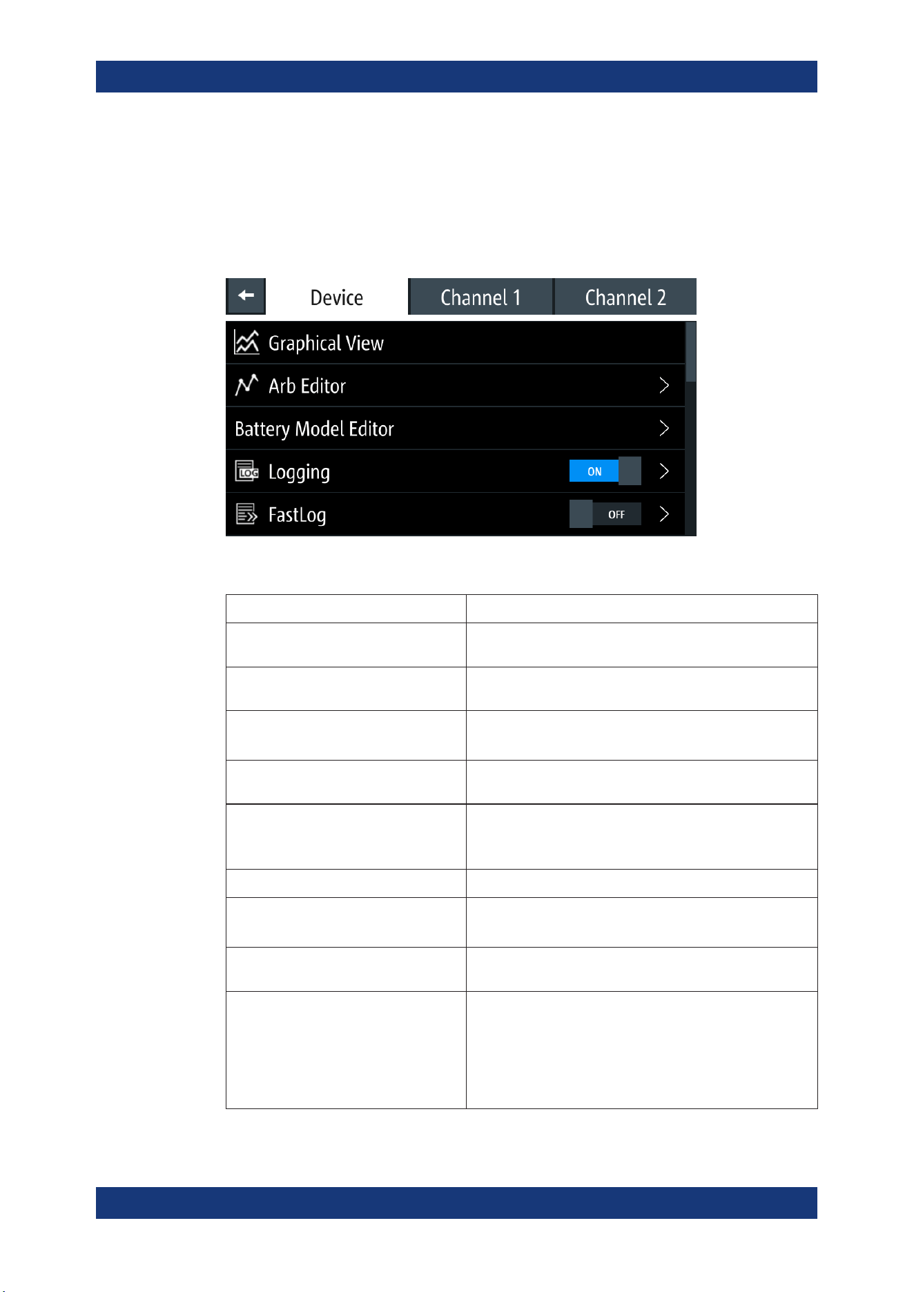
3. Select the "Device" tab to access the device menu.
Figure 5-9: Device menu
Menu Description
"Graphical View" Graphical display of available data source (e.g. voltage, cur-
rent, etc.)
"Arb Editor" Programs the waveform of voltage and current settings for the
channel output.
"Battery Model Editor" Available only with option R&S NGM-K106.
Edit new or existing battery model data.
"Logging" Data logging on the instrument timestamp, voltage, current
and power.
"FastLog" Available only with R&S NGM power supply series.
Fast data logging on the instrument timestamp, voltage and
current.
"Trigger" Activates the trigger source for SCPI command (*TRG).
"Digital Output" Available only with option R&S NGL-K103 or R&S NGM-K103.
Configures the output fault, output 1 and output 2.
"File Manager" File transfer function between instrument internal memory and
USB stick.
"Interfaces" Wireless LAN is available only with option R&S NGL-K102 or
R&S NGM-K102.
IEEE-488 (GPIB) interface is available only with option R&S
NGL-K105 or R&S NGM-K105.
Configures the network (WLAN, Wireless LAN), USB interface
and GPIB address
Front Panel Keys
Operating Basics
R&S
®
NGL200/NGM200
39User Manual 1178.8736.02 ─ 09
Menu Description
"User Button" Configures the shortcut key action (e.g. screenshot, trigger,
toggle logging, reset statistics, toggle touch).
"Screenshot" Captures screen image of the instrument.
"CSV Settings" Configures the file formatting for CSV file.
"Data & Time" Configures date, time and clock format of the instrument.
"Appearance" Configures brightness level for screen display and frontpanel
keys.
"Sound" Enables or disables beeper for trigger events (e.g. error, fuse
tripped, cc-mode continuous).
"Licenses" Displays license information and install license options.
"Device Information" Displays instrument information.
"Update Device" Performs firmware update on the instrument.
"Save/Recall Device Settings" File management on the instrument settings.
Resets instrument settings with factory default.
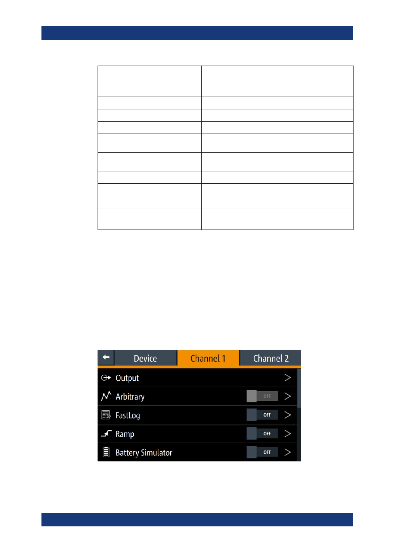
Channel menu
The "Channel 1" or "Channel 2" menu provides access to settings on channel output,
channel trigger conditions and output limit settings.
1. Press [Home] key.
The R&S NGL/NGM displays the home window.
2. Select the "Settings" button on the selected channel display area.
Alternatively, press [Settings] key to access the required channel menu.
3. Select the "Settings" button on the channel display area.
Alternatively, press [Settings] key to access the channel menu.
Figure 5-10: Channel 1 menu
Front Panel Keys

Operating Basics
R&S
®
NGL200/NGM200
40User Manual 1178.8736.02 ─ 09
Menus Description
"Output" Configures the output impedance, output delay time, trigger
actions and output mode (sink/source) of the output.
"Arbitrary" Configures the arbitrary sequence, sequence repeatability
response and the sequence ending behavior.
"Ramp" Configures the ramping time applied on the channel output.
"Battery Simulator" Available only with option R&S NGM-K106.
Activation of the "Battery Simulator" function and edit new bat-
tery model data.
"Overcurrent Protection (OCP)" Configures OCP protection settings ("Blowing Delay", "Initial
Delay" and linking channel) for the instrument.
"Overvoltage Protection (OVP)" Configures OVP protection settings (OVP level) for the instru-
ment.
"Overpower Protection (OPP)" Configures OPP protection settings (OPP power) for the
instrument.
"Ranges / DVM" The "Ranges" function provides the voltage and current mea-
surement range settings. With correct range settings, it increa-
ses the accuracy of measurements.
The DVM is available only with option R&S NGM-K104. It pro-
vides an independent digital voltmeter to measure input volt-
age.
"Constant Resistance" Configures the resistance used in the sink mode.
"Fast Transient Response" Enables/Disables the "Fast Transient Response" function on
the channel output.
"Safety Limits" Configures the voltage and current limit of the channel output.
5.3.1.3 User Key
The [*] key provides a shortcut function to one of the followings:
●
screenshot
●
trigger
●
data logging
●
reset statistics
●
toggle touchscreen input
The shortcut key is configurable in the "Device" > "User Button" menu. See
Chap-
ter 6.8, "User Key"
, on page 71.
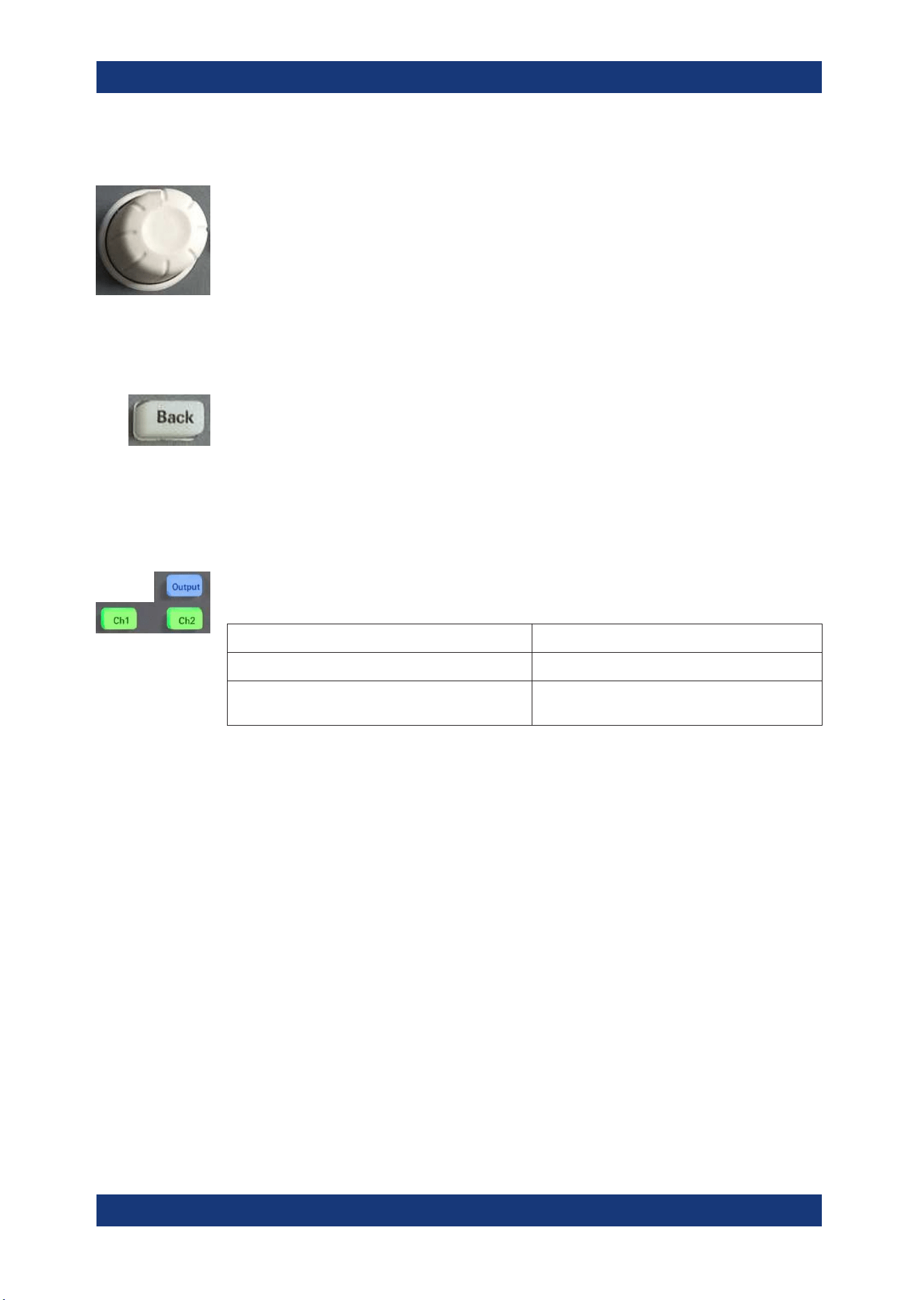
5.3.2 Navigation Controls
Navigation in the menu and setting of values can be done via rotary knob and [Back]
key.
Front Panel Keys
Operating Basics
R&S
®
NGL200/NGM200
41User Manual 1178.8736.02 ─ 09
Rotary knob
The rotary knob has several functions:
●
Increments (clockwise direction) or decrements (counter-clockwise direction) any
kind of numeric value when in editing mode
●
Navigates up (clockwise direction) or down (counterclock-wise direction) the menu
or menu items when rotated
●
When pressed and rotated, the rotary knob navigates along the set voltage or cur-
rent position in the home window
[Back] key
Using the [Back] key, you can do several things:
●
Navigate to the previous menu window
●
Close or discard changes made on the on-screen keypad
●
Close the instrument pop-up messages
5.3.3 Output and Channel Controls
Applicable only for 2-channel models (NGL202, NGM202), these keys control the
channel output settings of the instrument.
Function keys Description
[Ch1], [Ch2] Selects the respective channel for output.
[Output] Master output switch - it turns output for all
selected channels on or off.
5.4 Power Derating
The NGL202, NGM202 models include two identical channels with a continuous volt-
age range of 0 V to 20.05 V. The instrument provides a source of up to 6.01 A for volt-
age below 6 V and 3.01 A for voltage range from 6 V to 20 V.
Similar to NGL202, NGM202, the NGL201, NGM201 models provide a single channel
with an output power of up to 60 W.
Combination of the set voltage and current limit results in the following output perfor-
mance graph.
Power Derating
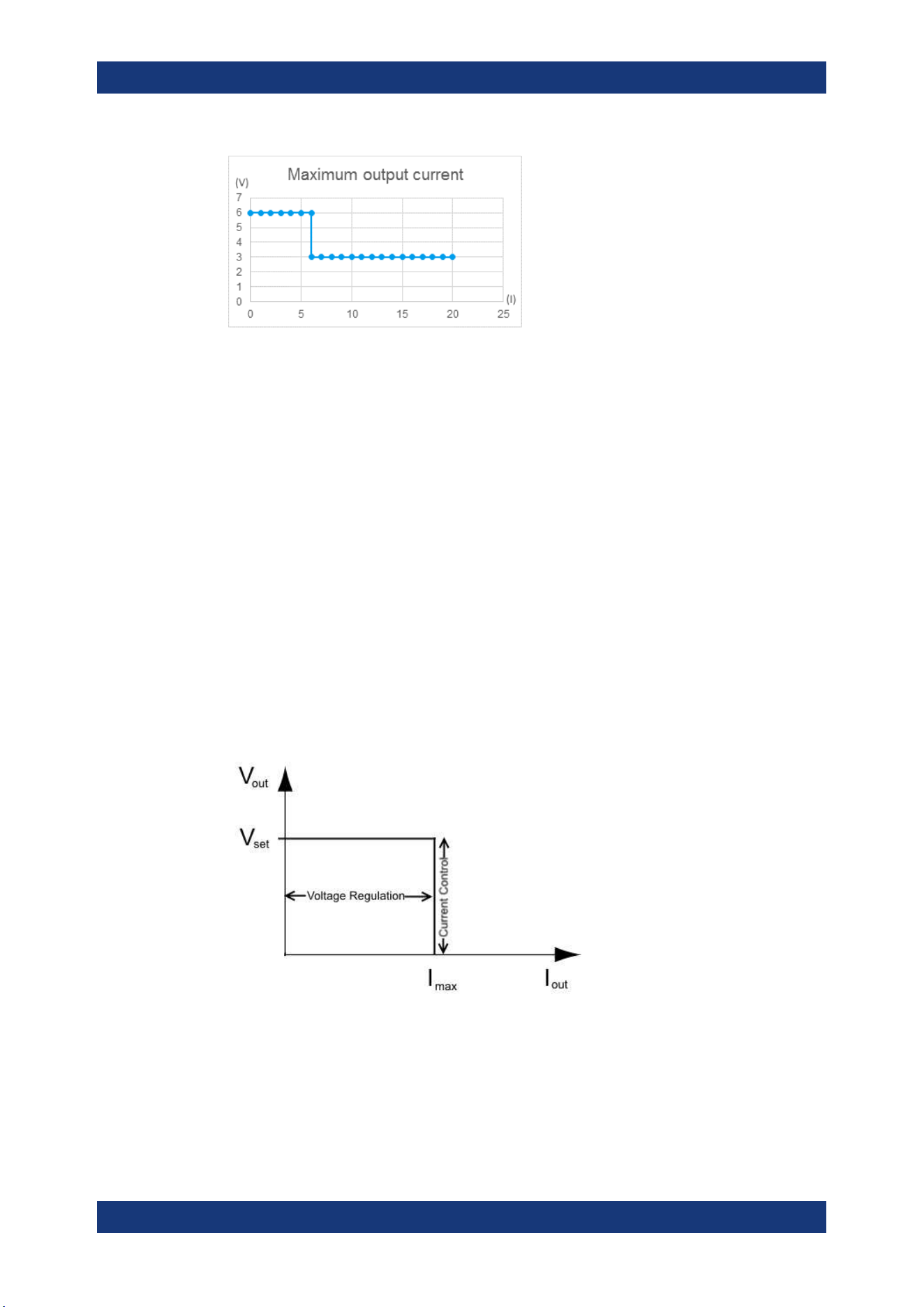
Operating Basics
R&S
®
NGL200/NGM200
42User Manual 1178.8736.02 ─ 09
Figure 5-11: Output performance graph
5.5 Operation Modes
The R&S NGL/NGM operates in three different modes, i.e. the constant voltage (CV),
constant current (CC) and constant resistance (CR). The instrument switches automat-
ically between CV and CC depending on the connected load. When CR is
configured,
the instrument is not switched to CR mode automatically, it will operate in CR mode
when sinking but source in CV or CC mode.
CV mode
Figure 5-12 shows that if the instrument is in the range of voltage regulation, the output
voltage V
out
remains constant while the current may increase to its maximum value I
max
when the connected load is increasing. In CV mode, the font text in the channel display
area changes to green.
See
Figure 5-3.
Figure 5-12: Current limit
CC mode
The current I
max
corresponds to the current setting adjustable in the instrument.
Operation Modes

Operating Basics
R&S
®
NGL200/NGM200
43User Manual 1178.8736.02 ─ 09
If I
out
reaches I
max
, the instrument switches to CC mode, i.e. the output current remains
constant and limited to I
max
even if the load increases. Instead, the output voltage V
out
decreases to almost zero with a short circuit. In CC mode, the font text in the channel
display area changes to red.
See Figure 5-3.
CR mode
To go into CR mode, the R&S NGL/NGM must operate in sink mode where current
flows into the instrument and "Constant Resistance" is enabled.
With "Constant Resistance" enabled and configured, the R&S NGL/NGM can set the
resistance in sink mode, this allows the R&S NGL/NGM to behave like an electronic
load which is useful in battery test application.
In CR mode, the font text in the channel display area changes to cyan.
See Figure 5-3.
Operation Modes
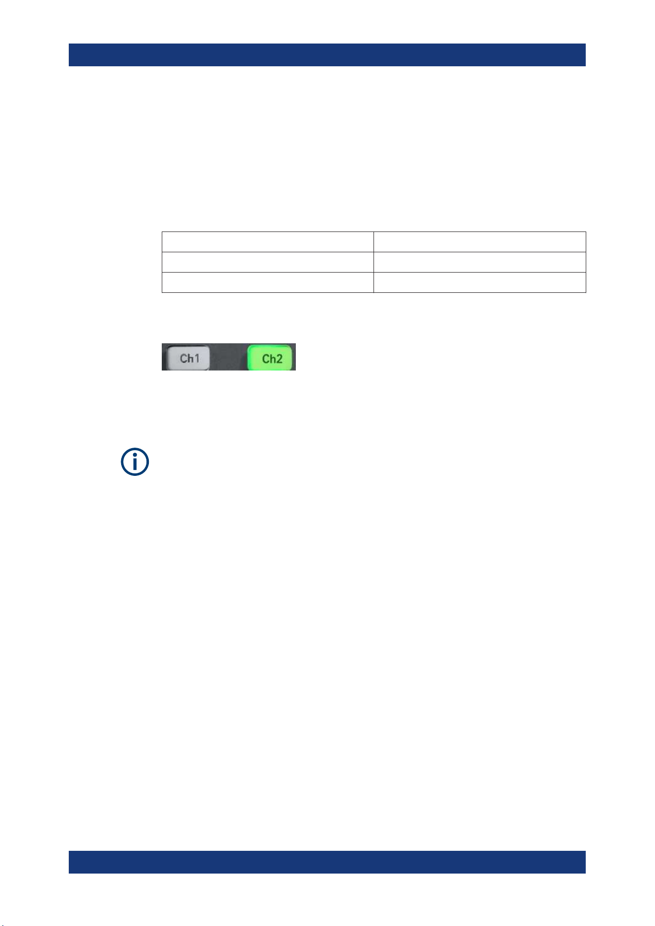
Instrument Functions
R&S
®
NGL200/NGM200
44User Manual 1178.8736.02 ─ 09
6 Instrument Functions
6.1 Setting the Channels Voltage and Current
The R&S NGL/NGM comes with the following instrument models:
Models Channels
NGL201, NGM201 Ch1
NGL202, NGM202 Ch1, Ch2
Toggle the respective channel key ([Ch1], [Ch2] ) on the front panel to select these
channels. When a channel is selected, the respective channel key illuminates.
Figure 6-1: Ch2 key illuminates when selected
Set output voltage and current
Voltage, current settings
If
Arbitrary function of a selected channel is enabled, the respective channel voltage or
current setting is disabled.
The R&S NGL/NGM adjusts the voltage values between 0 V to 20.05 V with a step
size of 1 mV and current values between 0 A to 6.01 A with a step size of 0.1 mA.
The setting of current value corresponds to the I
max
of the respective channel. It is
advisable to set the current limit before operating the instrument to prevent damage to
the load and instrument in the case of malfunction such as a short-circuit.
1. Press [Home] key.
The R&S NGL/NGM displays the home window.
2. Set voltage or current in the home window.
The R&S NGL/NGM displays the on-screen keypad to set value.
3. Enter the required voltage or current value.
4. Confirm value with the unit key (V/mV or A/mA).
5. Press the required channel key ([Ch1] or [Ch2]) on the front panel.
The selected channel key is illuminated. See
Figure 6-1.
6. Press the [Output] key on the front panel.
The R&S NGL/NGM outputs the set voltage of the selected channel and displays
the corresponding values in the home window.
Setting the Channels Voltage and Current

Instrument Functions
R&S
®
NGL200/NGM200
45User Manual 1178.8736.02 ─ 09
For more information on the operation modes, see Chapter 5.5, "Operation
Modes", on page 42.
Figure 6-2: Voltage and current settings in the instrument
6.2 Activating the Channels Output
The outputs of all the channels (Ch1, Ch2) can be switched on or off by toggling the
[Output] key on the front panel.
By default, the output is turned off when the instrument is switched on. The output is
also automatically turned off when no channel is selected. This design prevents a con-
nected load from being damaged unintentionally.
1. Press the required channel key.
Selected channel key (Ch1, Ch2) illuminates.
2. Press [Output] key.
The R&S NGL/NGM outputs the set voltage of the selected channel.
Depending on the operating mode, the font text in the channel display area shows
green in CV mode, red in CC mode and cyan in CR mode.
Note: The R&S NGL/NGM goes into CR mode when CR is enabled and the instru-
ment operates in sink mode.
See
Chapter 5.5, "Operation Modes", on page 42.
See also Chapter 5.4, "Power Derating", on page 41.
Multiple outputs can be turned on or off at the same time.
Activating the Channels Output
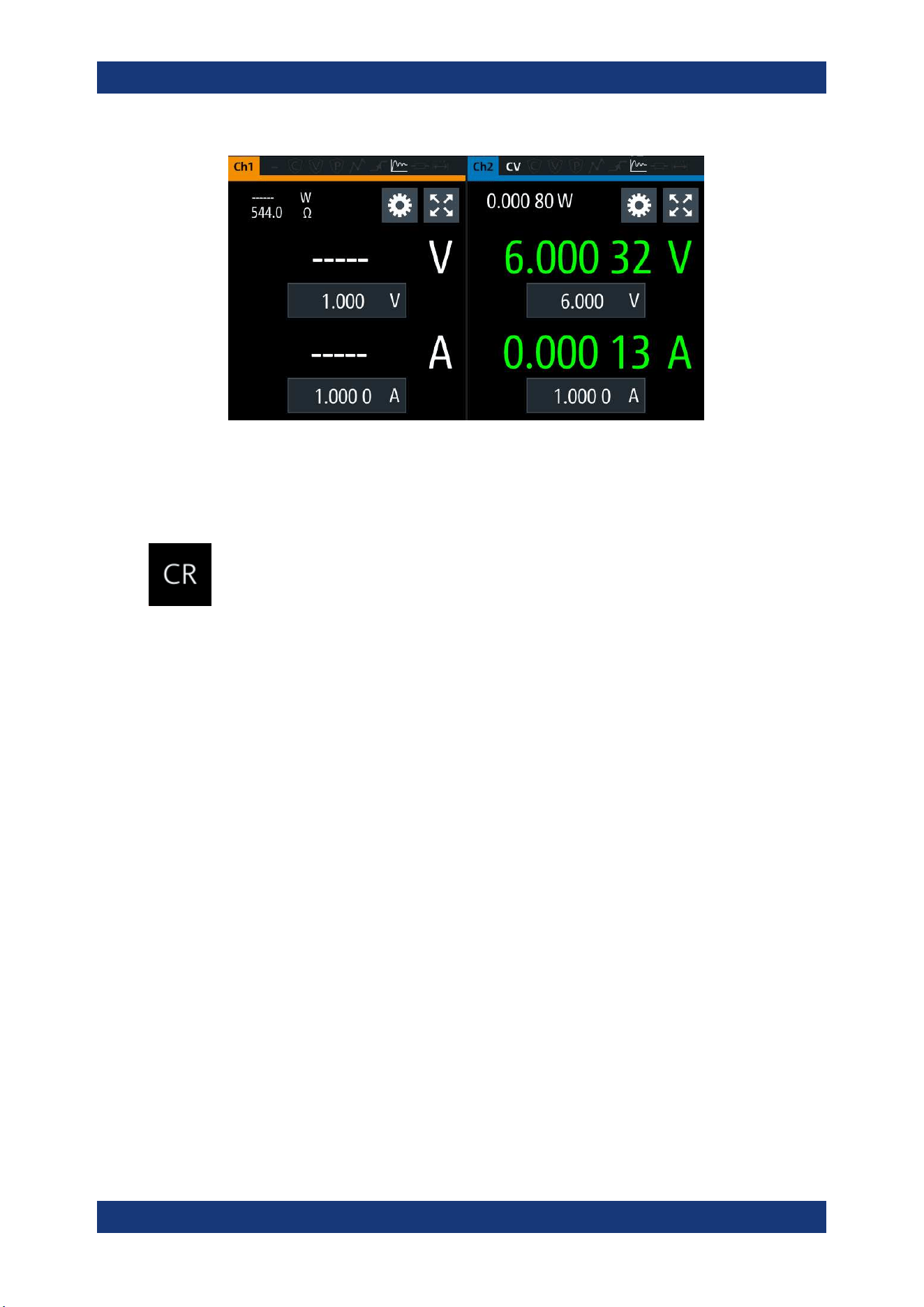
Instrument Functions
R&S
®
NGL200/NGM200
46User Manual 1178.8736.02 ─ 09
Figure 6-3: Output of Ch2 in CV mode
6.2.1 Set Constant Resistance
By enabling the constant resistance (CR) mode, you can operate the R&S NGL/NGM
as an electronic load in sink mode. This allows you to perform testing that requires a
constant load resistor in your application.
1. Press [Settings] key.
The R&S NGL/NGM displays the device/channel menu window.
2. Select the required channel tab to apply constant resistance.
The R&S NGL/NGM displays the selected channel menu.
3. Select the "Constant Resistance" from the menu.
The R&S NGL/NGM displays the "Constant Resistance" dialog.
4. Activate the "Enabled" menu item.
When operates in sink mode condition, the R&S NGL/NGM displays the "Constant
Resistance" icon on the selected channel status bar information.
5. Set the required resistance.
The R&S NGL/NGM displays the on-screen keypad to set the value.
6. Confirm value with the unit key (mΩ or Ω).
The value for "Constant Resistance" is rounded to the nearest 1 Ω or 0.1 Ω,
depending on the value.
Activating the Channels Output
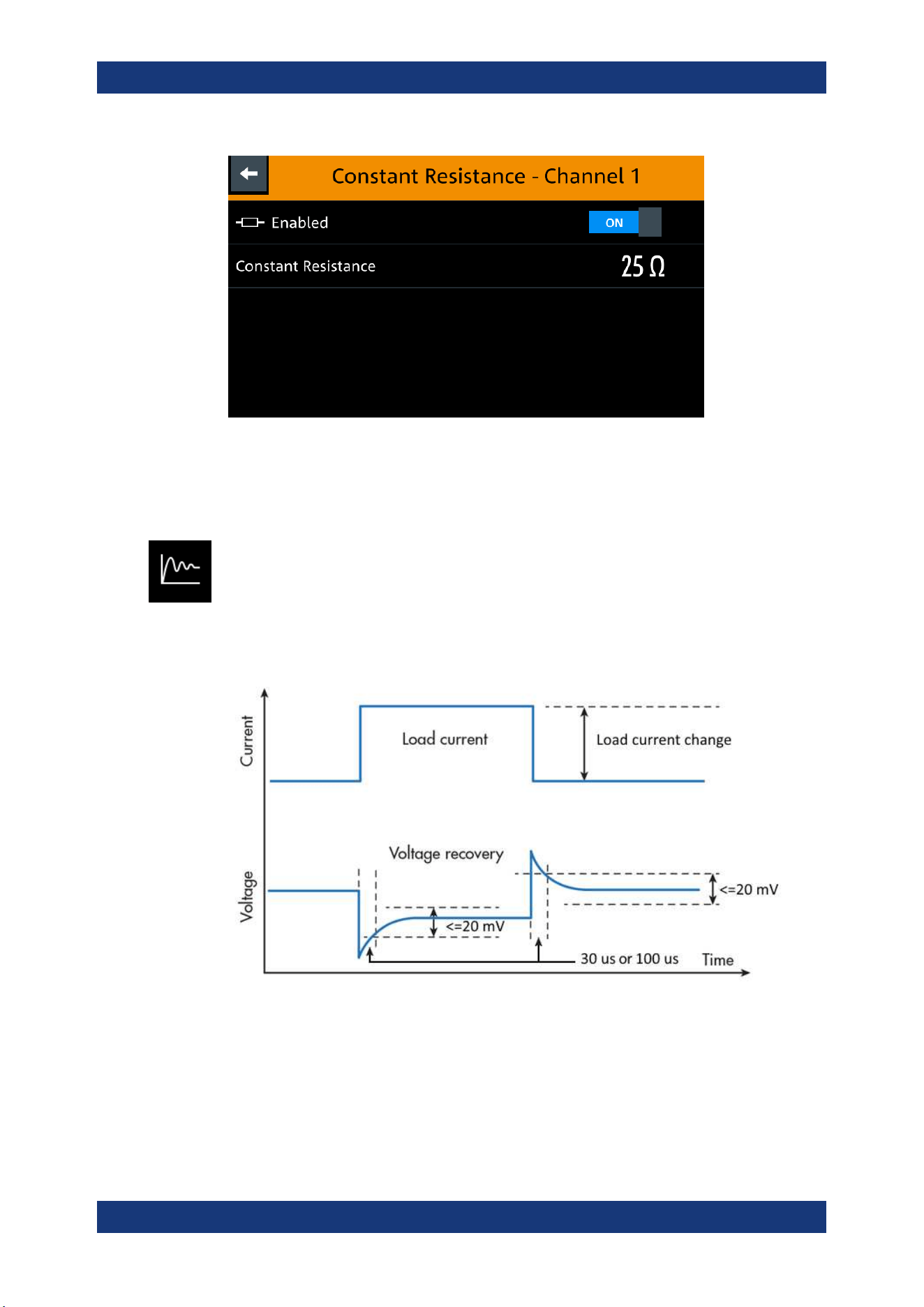
Instrument Functions
R&S
®
NGL200/NGM200
47User Manual 1178.8736.02 ─ 09
Figure 6-4: Constant resistance dialog
6.2.2 Fast Transient Response
With fast transient response, the R&S NGL/NGM is able to quickly stabilize the output
voltage upon a step change in the load current.
Load transient recovery time can be switched between 30 μs ("Fast Transient
Response" = "ON") or 100 μs ("Fast Transient Response" = "OFF") for the output volt-
age to recover and stay within 20 mV of the nominal output voltage follows by a step
change in the load current.
Figure 6-5: Transient response graph
1. Press [Settings] key.
The R&S NGL/NGM displays the device/channel menu window.
2. Select the required channel tab to apply fast transient response.
The R&S NGL/NGM displays the selected channel menu.
Activating the Channels Output
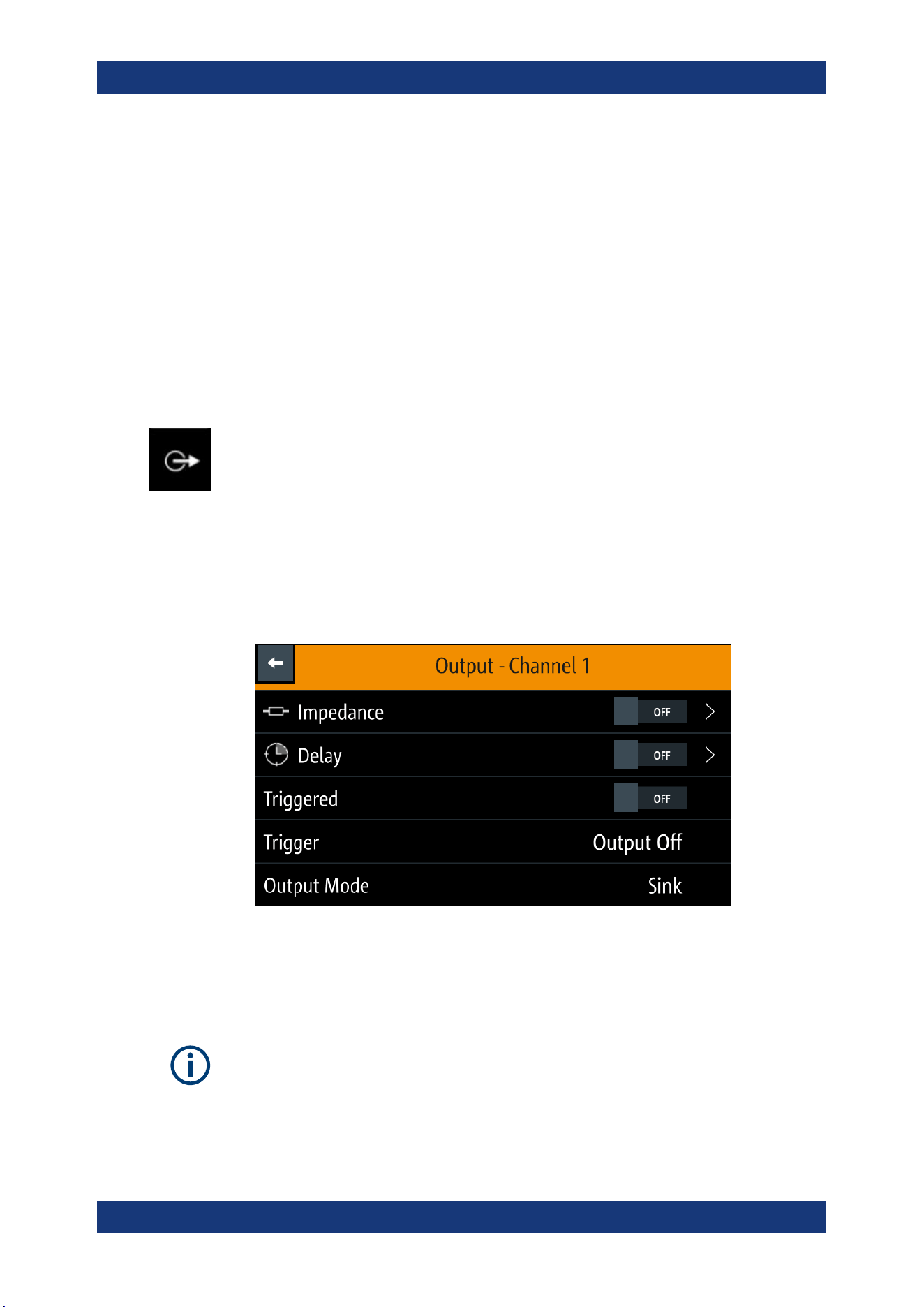
Instrument Functions
R&S
®
NGL200/NGM200
48User Manual 1178.8736.02 ─ 09
3. Activate the "Fast Transient Response" from the menu.
The R&S NGL/NGM applies the fast transient response on the operating condition
and displays the "Fast Transient Response" icon on the selected channel status
bar information.
The setting of "Fast Transient Response" affects the output voltage control loop
behavior. See
Chapter 6.2.3.1, "Impedance", on page 48.
If activated, the focus is on control loop speed, which is recommended for resistive
loads. Otherwise, the focus is on stability and should be preferred for capacitive or
inductive loads.
6.2.3 Output
The "Output" menu provides the settings for output impedance, output delay and trig-
gers action
on the output mode.
1. Press [Settings] key.
The R&S NGL/NGM displays the device/channel menu window.
2. Select the required channel tab to apply output delay.
The R&S NGL/NGM displays the selected channel menu.
3. Select the "Output" menu item.
The R&S NGL/NGM displays the "Output" dialog.
Figure 6-6: Output delay dialog
6.2.3.1 Impedance
The output impedance function is disabled during voltage ramp time of "Ramp" func-
tion. See Chapter 6.7.2, "Ramp", on page 70.
1. Select the "Impedance" menu item to configure the required values.
Activating the Channels Output
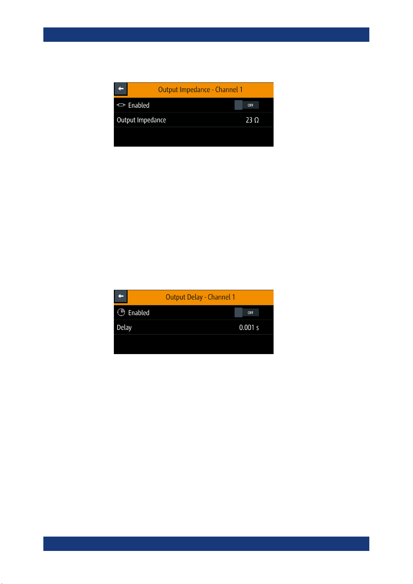
Instrument Functions
R&S
®
NGL200/NGM200
49User Manual 1178.8736.02 ─ 09
The R&S NGL/NGM displays the "Output Impedance" dialog.
2. Set the required value.
The R&S NGL/NGM displays the onscreen keypad for entry.
3. Confirm value with the unit keys.
The output impedance control loop depends on the setting "Fast Transient Response".
See
Chapter 6.2.2, "Fast Transient Response", on page 47.
The output impedance is only active during CV (constant voltage) operation mode.
6.2.3.2 Delay
1. Select the "Delay" menu item to configure the required values.
The R&S NGL/NGM displays the "Output Delay" dialog.
2. Set the required value.
The R&S NGL/NGM displays the onscreen keypad for entry.
3. Confirm value with the unit keys.
The output delay is the time between the "Output On" event and the available voltage
at the output terminals. See
Figure 6-7.
Activating the Channels Output
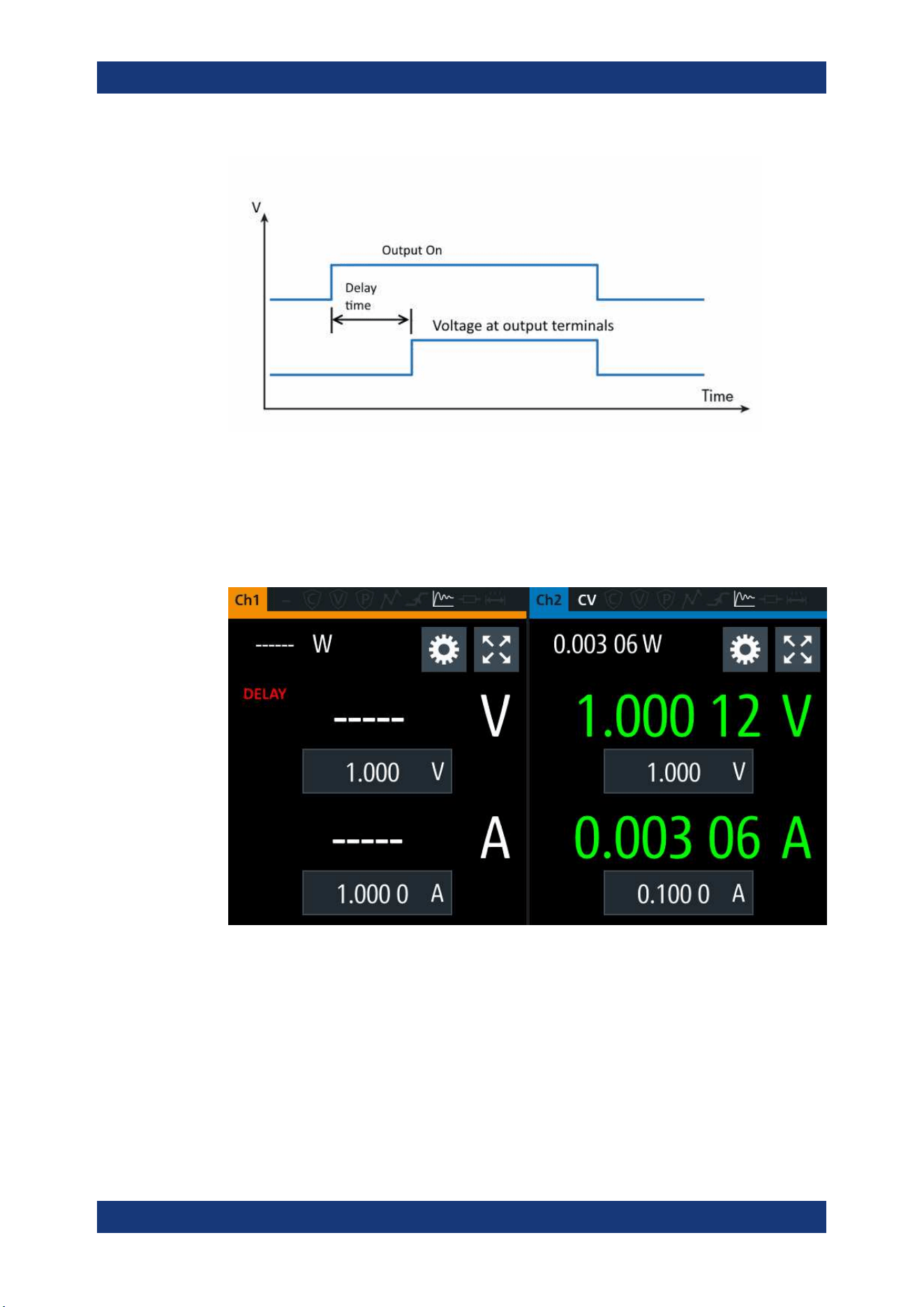
Instrument Functions
R&S
®
NGL200/NGM200
50User Manual 1178.8736.02 ─ 09
Figure 6-7: Output delay at the output terminals
When the instrument output delay is activated, the front panel of the respective chan-
nel key (i.e [Ch1], [Ch2]) blinks in green and a "DELAY" red text is displayed at the
channel display area of the respective channel. See
Figure 6-8.
These operating behaviors resume to normal after the delay time.
Figure 6-8: Delay text at channel display area
6.2.3.3 Trigger Events
1. Select the "Triggered" menu item to activate the trigger event corresponding to the
trigger parameters.
See
Figure 6-18.
2. Select the "Trigger" menu item to set the action if a trigger event happens.
Activating the Channels Output
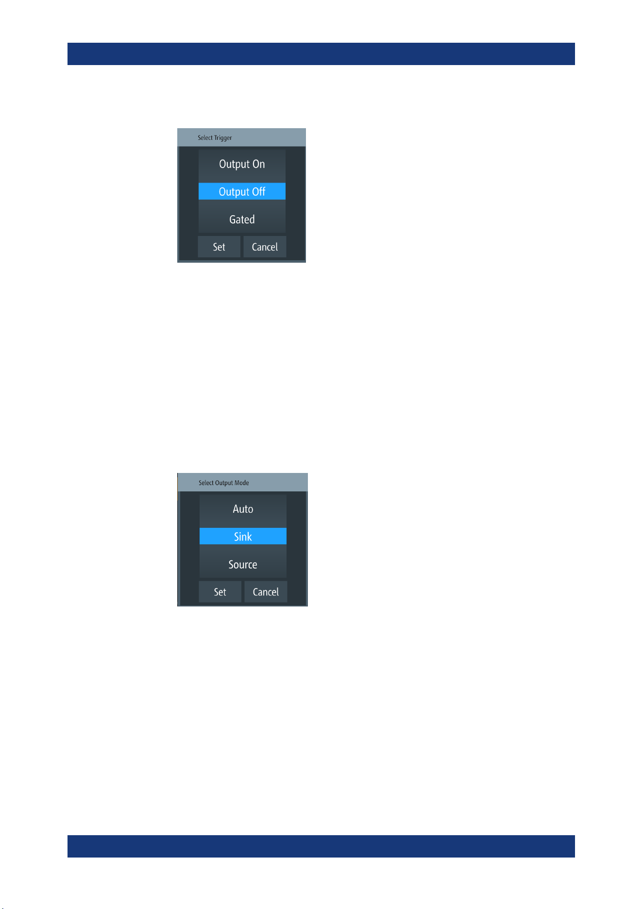
Instrument Functions
R&S
®
NGL200/NGM200
51User Manual 1178.8736.02 ─ 09
The R&S NGL/NGM displays the "Trigger" dialog.
3. Select the required trigger action.
● "Output On": If triggered, the selected output channel is turned on.
● "Output Off": If triggered, the selected output channel is turned off.
● "Gated": If triggered, the selected output channel is gated.
4. Select "Set" to configure the trigger action.
6.2.3.4 Output Mode
1. Select the "Output Mode" menu item to set the output mode. See "Source and sink
current" on page 26.
The R&S NGL/NGM displays the "Output mode" dialog.
2. Select the required output mode.
● Auto: Depending on the voltage across the output terminal, the R&S NGL/NGM
goes into sink or source mode.
● Sink : The R&S NGL/NGM goes to sink mode, current flows into the instru-
ment. On display, the current shown negative current.
● Source: The R&S NGL/NGM goes to source mode, current flows out from the
instrument.
Note: If "Sink" mode is selected, the source current is limited to 1 mA. Otherwise, if
"Source" is selected, the sink current is limited to 1 mA.
3. Select "Set" to configure the trigger condition.
Activating the Channels Output
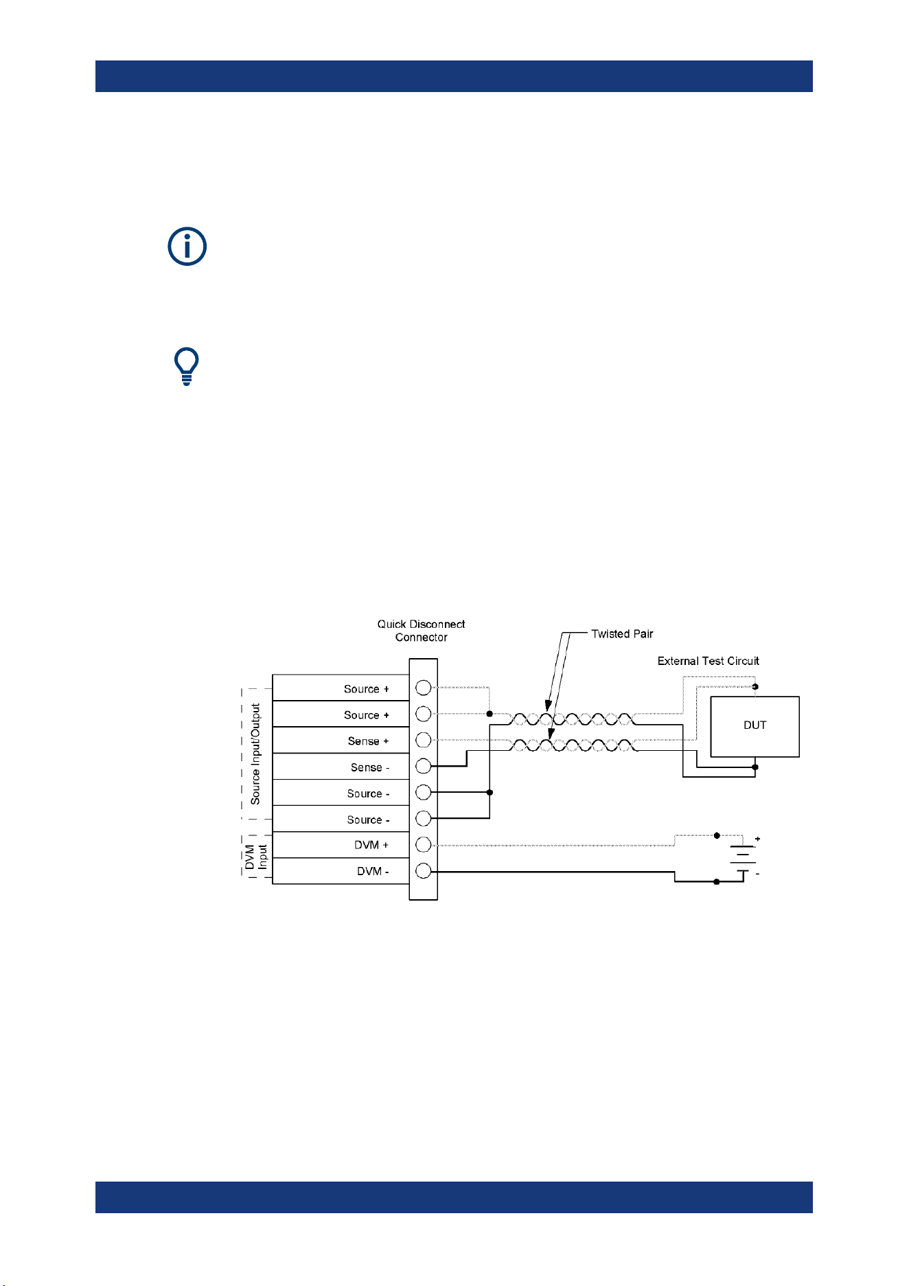
Instrument Functions
R&S
®
NGL200/NGM200
52User Manual 1178.8736.02 ─ 09
6.3 Ranges / Digital Voltmeter (DVM)
Instrument option
R&S NGM-K104 (P/N: 3643.9927.02) option is required for Digital Voltmeter measure-
ments.
Ranges / Digital Voltmeter (DVM) is only available on NGM devices.
Sense connection has to be connected to the load for better performance.
Equipped with option R&S NGM-K104, the R&S NGM provides an independent digital
voltmeter (DVM) to measure input voltage. See the datasheet for the full range of vol-
tages that DVM supported.
Connection for the DVM measurement is wired from the instrument rear panel.
If DVM measurement is activated, the displaying of output voltage is not possible on
the same channel. See
"Output terminals" on page 23.
See
Figure 6-9 for the wiring example on measuring a voltage source from rear panel
connector.
Figure 6-9: Rear panel four-wire sense and DVM connection
1. Press [Settings] key.
The R&S NGL/NGM displays the device/channel menu window.
2. Select the required channel tab to configure DVM function.
The R&S NGL/NGM displays the selected channel menu.
3. Select the "Ranges / DVM" from the menu.
The R&S NGL/NGM displays the "Ranges / DVM" dialog.
Ranges / Digital Voltmeter (DVM)
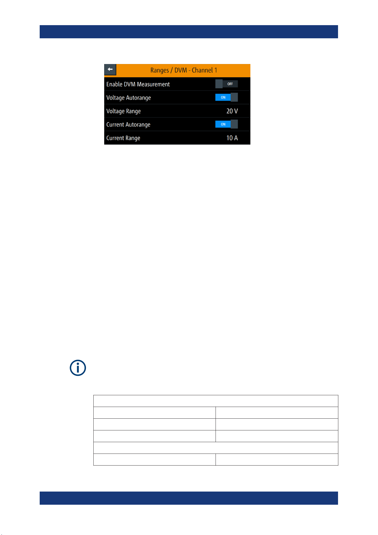
Instrument Functions
R&S
®
NGL200/NGM200
53User Manual 1178.8736.02 ─ 09
Figure 6-10: Range/DVM dialog
Note: The "Voltage Autorange" and "Voltage Range" are not available if DVM is
enabled.
4. Activate the "Enable DVM Measurement" menu item.
The R&S NGL/NGM enables the DVM measurement and displays a DVM text in
the channel display area. See
Chapter 5.1.2, "Channel Display Area", on page 32.
5. To configure the voltage range, set "Enable DVM Measurement" to "OFF".
Select any of the following to configure the voltage and current measurement
range.
● "Voltage Autorange" / "Current Autorange": Best display of voltage or current
measurement range
● "Voltage Range" / "Current Range": See Table 6-1.
To select the voltage or current range, set the auto range to "OFF".
Measurement range
Correct setting of voltage and current range increases the accuracy of the voltage/
current measurements. Measuring outside the range values may result in invalid mea-
surements with OVERLOAD indicator.
See the datasheet for the measurement accuracy according to the measurement range
selected.
It is recommended to set a manual measurement range for very frequent range
changes.
Table 6-1: Voltage and current range
Available voltage ranges
Auto Instrument selects the best range to display.
5 V Accuracy from 0 V to 5 V.
20 V Accuracy from 0 V to 20.05 V.
Available current ranges
Auto Instrument selects the best range to display.
Ranges / Digital Voltmeter (DVM)
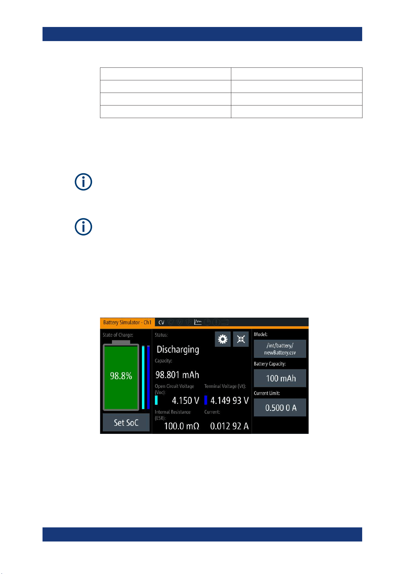
Instrument Functions
R&S
®
NGL200/NGM200
54User Manual 1178.8736.02 ─ 09
10 A Accuracy from 0 A to 10 A.
1 A Accuracy from 0 A to 1 A.
100 mA Accuracy from 0 A to 100 mA.
10 mA Accuracy from 0 A to 10 mA.
6.4 Battery Simulator
Instrument option
R&S NGM-K106 (P/N: 3636.6626.02) option is required.
Battery Simulator is only available on NGM devices.
If battery simulator is active, the function
safety limits cannot be used.
Equipped with battery simulator option, the R&S NGM can be used as a battery source
in developing products whereby battery is not ready for testing, such as phones and
portable devices.
The R&S NGM provides a battery simulator editor to configure the battery model at dif-
ferent states to analyze the products behavior under specific conditions. Different bat-
tery state of charge (SoC) can be simulated rapidly without waiting for the charging or
discharging process of a normal battery when conducting tests.
Figure 6-11: Battery simulator for Ch1
Battery Simulator
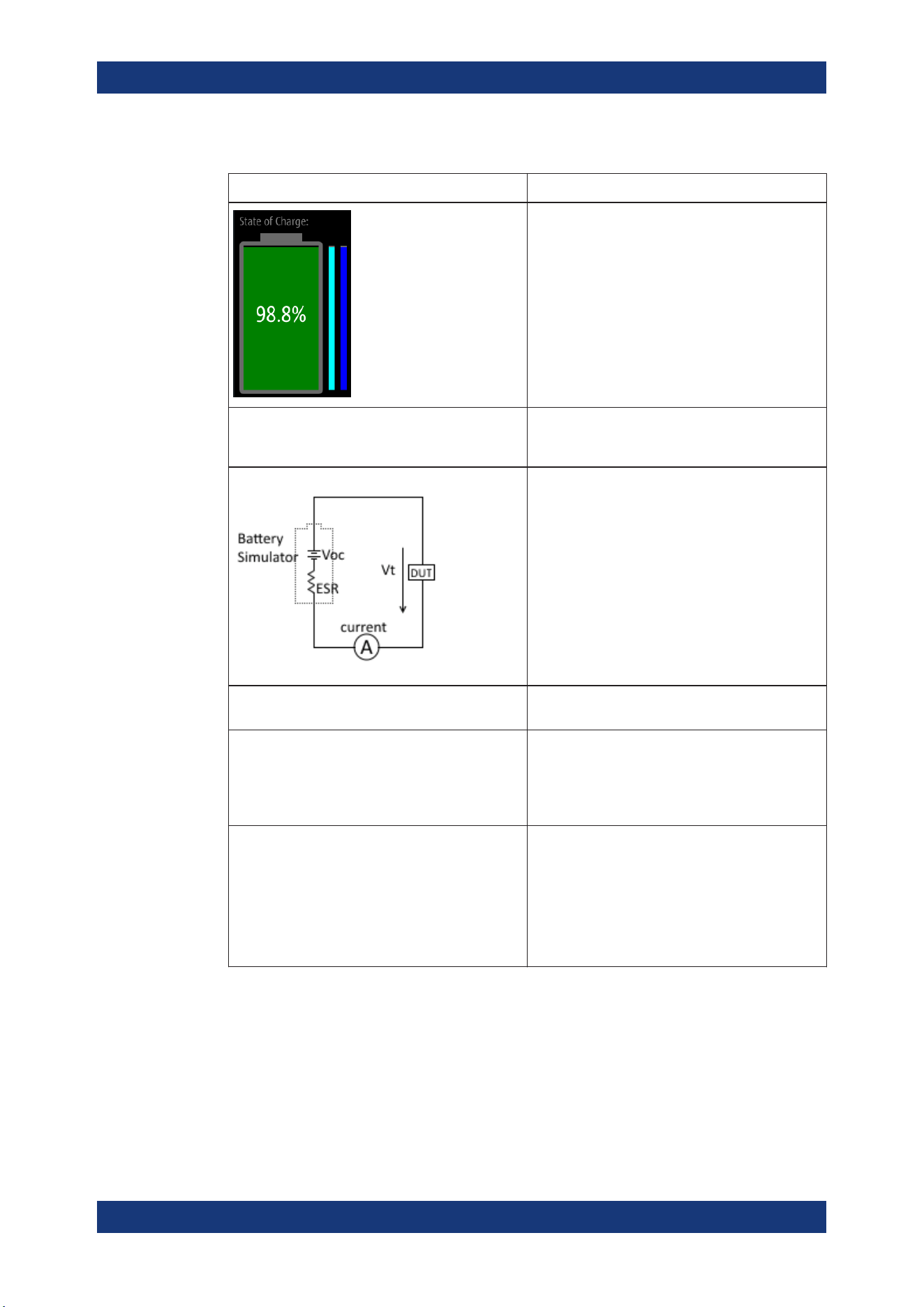
Instrument Functions
R&S
®
NGL200/NGM200
55User Manual 1178.8736.02 ─ 09
Table 6-2: Battery simulator parameters
Battery simulator parameters Descriptions
The battery symbol represents the state of charge.
The light blue bar indicates the open circuit voltage
and the dark blue bar indicates the terminal voltage.
The differences between both bars show the voltage
drops on internal resistance.
Scale: the maximum of both bars are the maximum
defined voltage in the battery model and the mini-
mum is the minimal defined voltage.
See Figure 6-13.
SoC State of charge represents the current battery
capacity, e.g. 85% SoC represents that 15% of bat-
tery capacity is used.
The open circuit voltage, Voc is the voltage between
the battery terminals with no load applied. The Voc
depends on the loaded battery model and the cur-
rent SoC.
The internal resistance, ESR (also known as Equiv-
alent Series Resistance) depends on the loaded
battery model and current SoC.
The terminal voltage, Vt is the voltage between the
battery terminals with applied voltage drop over the
ESR. Terminal voltage varies with charge or dis-
charge current.
Model The loaded battery model applied in the battery sim-
ulator.
Battery capacity The storage capacity for the battery:
●
Minimum value: 1 µAh
●
Maximum value: 100 kAh
Editing a new value here overwrites the current
value loaded from the
battery model editor.
Current limit In addition to the resistance of the battery model,
current flow can be limited to protect possibly sensi-
tive equipment connected to the device.
There are three current limit settings available:
●
SoC < 0 % (the battery is empty)
●
SoC 0 % to 100 % (the battery is in normal
operation mode)
●
SoC > 100 % (the battery is fully loaded)
1. Press [Settings] key.
The R&S NGM displays the device/channel menu window.
2. Select the required channel tab to configure the battery simulator function.
The R&S NGM displays the selected channel menu.
3. Select the "Battery Simulator" menu item from the menu.
The R&S NGM displays the "Battery Simulator" dialog.
Battery Simulator
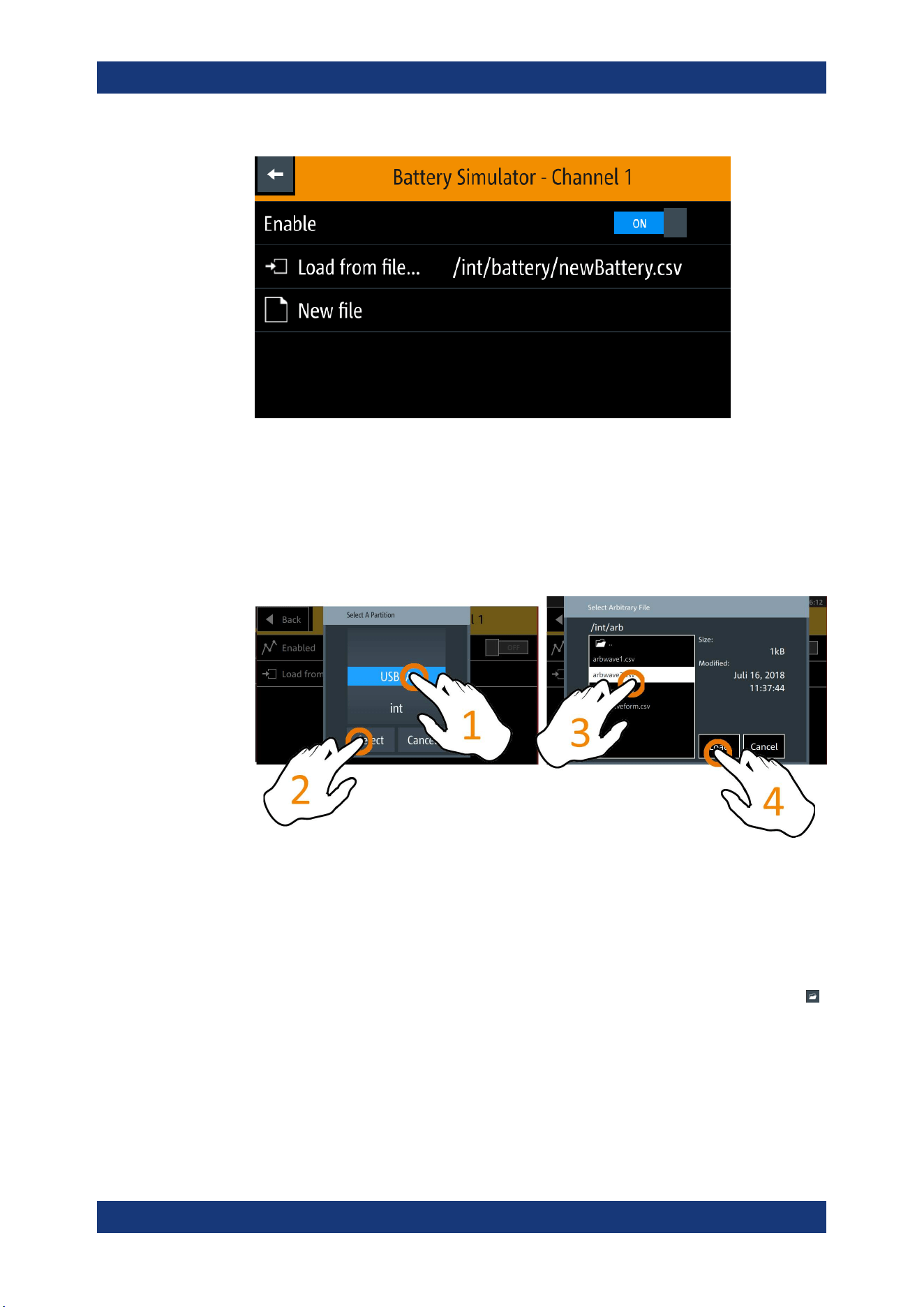
Instrument Functions
R&S
®
NGL200/NGM200
56User Manual 1178.8736.02 ─ 09
Figure 6-12: Battery simulator dialog
4. Select the "Load from file..." to load the battery model file.
The R&S NGM opens a dialog to select the source and file location.
5. Select the required source and file location.
Alternatively, select "New file" to create a new battery model. The R&S NGM opens
the
battery model edior dialog to edit the new battery model file.
6. Activate the "Enabled" menu item.
The R&S NGM enables the battery simulation function.
Battery model editor
The battery model editor allows you to create and edit battery models with custom
behavior. In the editor, the open circuit voltage (Voc) and the equivalent series resist-
ance (ESR) can be defined for different states of charge (SoC) of the battery. Select
to open the list of available battery model files.
Battery Simulator
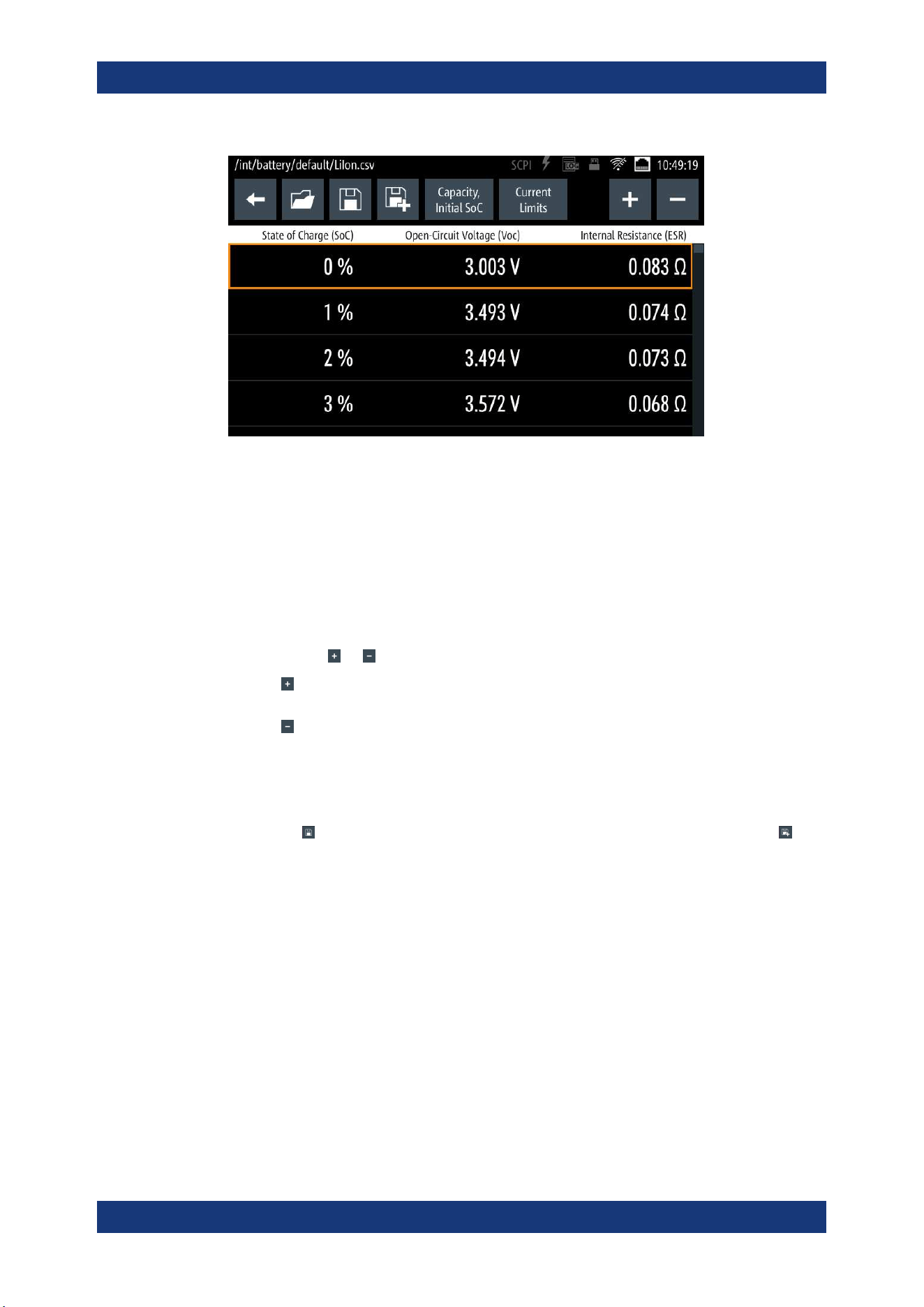
Instrument Functions
R&S
®
NGL200/NGM200
57User Manual 1178.8736.02 ─ 09
Figure 6-13: Battery model editor dialog
1. Configure the "Battery Model Editor" with the required state of charge (SoC), open-
circuit voltage (Voc) and internal resistance (ESR).
The R&S NGM displays the on-screen keypad for data entry.
The R&S NGL/NGM displays the on-screen keypad for data entry.
See also
Table 6-2.
2. Confirm values with the unit keys.
3.
Select the
or icon to add or remove a row of data from the model.
●
: A new row of data is added to the model. It is initially filled with the data of
the currently selected row.
●
: Removes the currently selected row from the model.
4. Select "Capacity" and "Initial SoC" to configure the capacity and initial state of
charge of the battery.
The R&S NGM displays the on-screen keypad for data entry.
5.
Select
(existing file) to save the changes made to an existing file or select
(new file) to save the table as a new battery model file.
The R&S NGM displays a popup message to show that the file was saved suc-
cessfully.
Battery Simulator

Instrument Functions
R&S
®
NGL200/NGM200
58User Manual 1178.8736.02 ─ 09
6.5 Protection
There are various ways in which the R&S NGL/NGM protects itself and the connected
load from damage due to overvoltage, overcurrent and overpower drawn by the load
during testing.
1. Press [Settings] key.
The R&S NGL/NGM displays the device/channel menu window.
2. Select the required channel tab to configure the various protection dialogs.
The R&S NGL/NGM displays the selected channel menu.
6.5.1 Overcurrent Protection (OCP)
When the drawn current exceeds the limit set for the respective channels, an alert is
triggered and the affected channels are turned off according to the settings configured
in the OCP dialog.
1. Select "Overcurrent Protection (OCP)" from the menu.
The R&S NGL/NGM displays the OCP dialog.
Protection
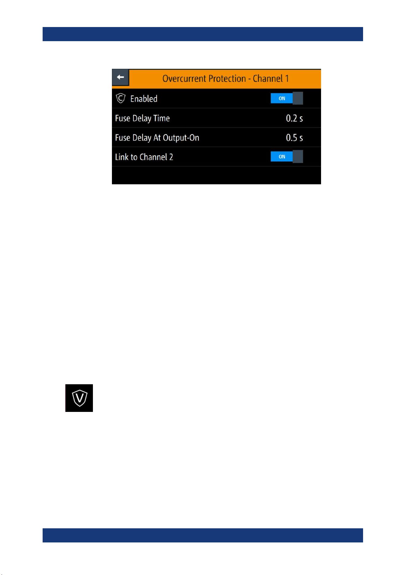
Instrument Functions
R&S
®
NGL200/NGM200
59User Manual 1178.8736.02 ─ 09
Figure 6-14: Overcurrent protection dialog
2. Activate the "Enabled" menu item.
The R&S NGL/NGM enables the OCP and displays the OCP icon on the selected
channel status bar information.
3. Set the required "Fuse Delay Time" and "Fuse Delay At Output-On".
The R&S NGL/NGM displays the on-screen keypad to set the values.
● "Fuse Delay Time": The time taken to turn off the affected channel after OCP is
triggered.
● "Fuse Delay At Output-On": The time taken after channel output is turned on
before OCP is put into operation.
4. Confirm value with the unit key (ms or s).
5. Activate the "Link to Channel 2" or "Link to Channel 1" menu item.
● ON: The linked channel is turned off when an OCP event is triggered.
● OFF: The linked channel is not affected when an OCP event is triggered.
6.5.2 Overvoltage Protection (OVP)
When the output voltage exceeds the limit set for the respective channel, an alert is
triggered and the affected channel is turned off according to the settings configured in
the OVP dialog.
1. Select "Overvoltage Protection (OVP)" from the menu.
The R&S NGL/NGM displays the OVP dialog.
Protection
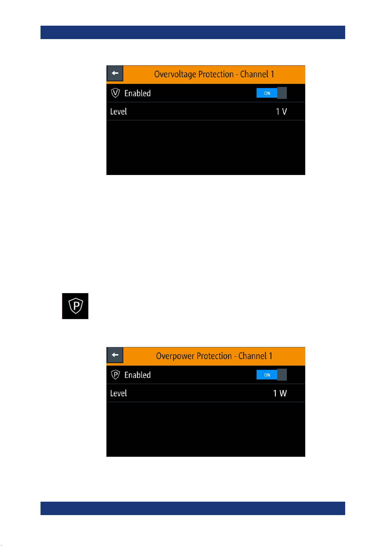
Instrument Functions
R&S
®
NGL200/NGM200
60User Manual 1178.8736.02 ─ 09
Figure 6-15: Overvoltage protection dialog
2. Activate the "Enabled" menu item.
The R&S NGL/NGM enables the OVP and displays the OVP icon on the selected
channel status bar information.
3. Set the required level for OVP.
The R&S NGL/NGM displays the on-screen keypad to set the value.
4. Confirm value with the unit key (mV or V).
6.5.3 Overpower Protection (OPP)
When the output power exceeds the limit set for the respective channels, an alert is
triggered and the affected channels are turned off according to the settings configured
in the OPP dialog.
1. Select "Overpower Protection (OPP)" menu item.
The R&S NGL/NGM displays the OPP dialog.
Figure 6-16: Overpower protection dialog
Protection
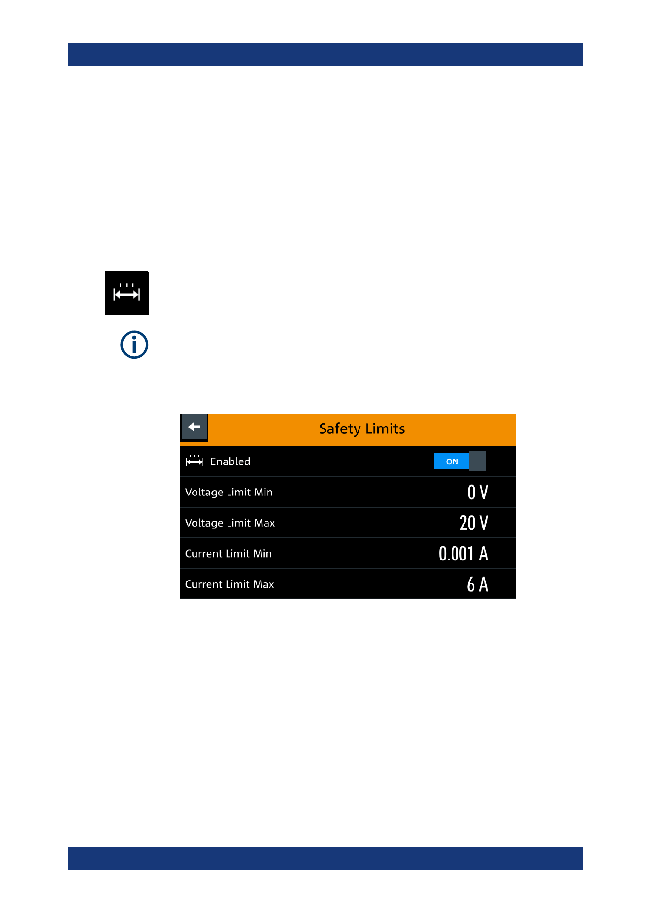
Instrument Functions
R&S
®
NGL200/NGM200
61User Manual 1178.8736.02 ─ 09
2. Activate the "Enabled" menu item.
The R&S NGL/NGM enables the OPP and displays the "Overpower Protection
(OPP)" icon on the selected channel status bar information.
3. Set the required level for OPP.
The R&S NGL/NGM displays the on-screen keypad to set the value.
4. Confirm value with the unit key (mW or W).
6.5.4 Safety Limits
With safety limits set in the instrument, the range of the output voltage and/or output
current can be limited. The safety limit prevents inadvertently setting values dangerous
for the connected DUT.
The "Safety Limits" function is disabled if
Arbitrary function or Battery Simulator func-
tion is in use.
1. Select "Safety Limits" menu item from the menu.
The R&S NGL/NGM displays the "Safety Limits" dialog.
Figure 6-17: Safety limits dialog
2. Activate the "Enabled" menu item.
The R&S NGL/NGM limits the set voltage and current level and displays the
"Safety Limits" icon on the selected channel status bar information.
3. Set the required minimum and maximum value for voltage and current level.
The R&S NGL/NGM displays an on-screen keypad to set the value.
4. Confirm value with the unit key.
Protection
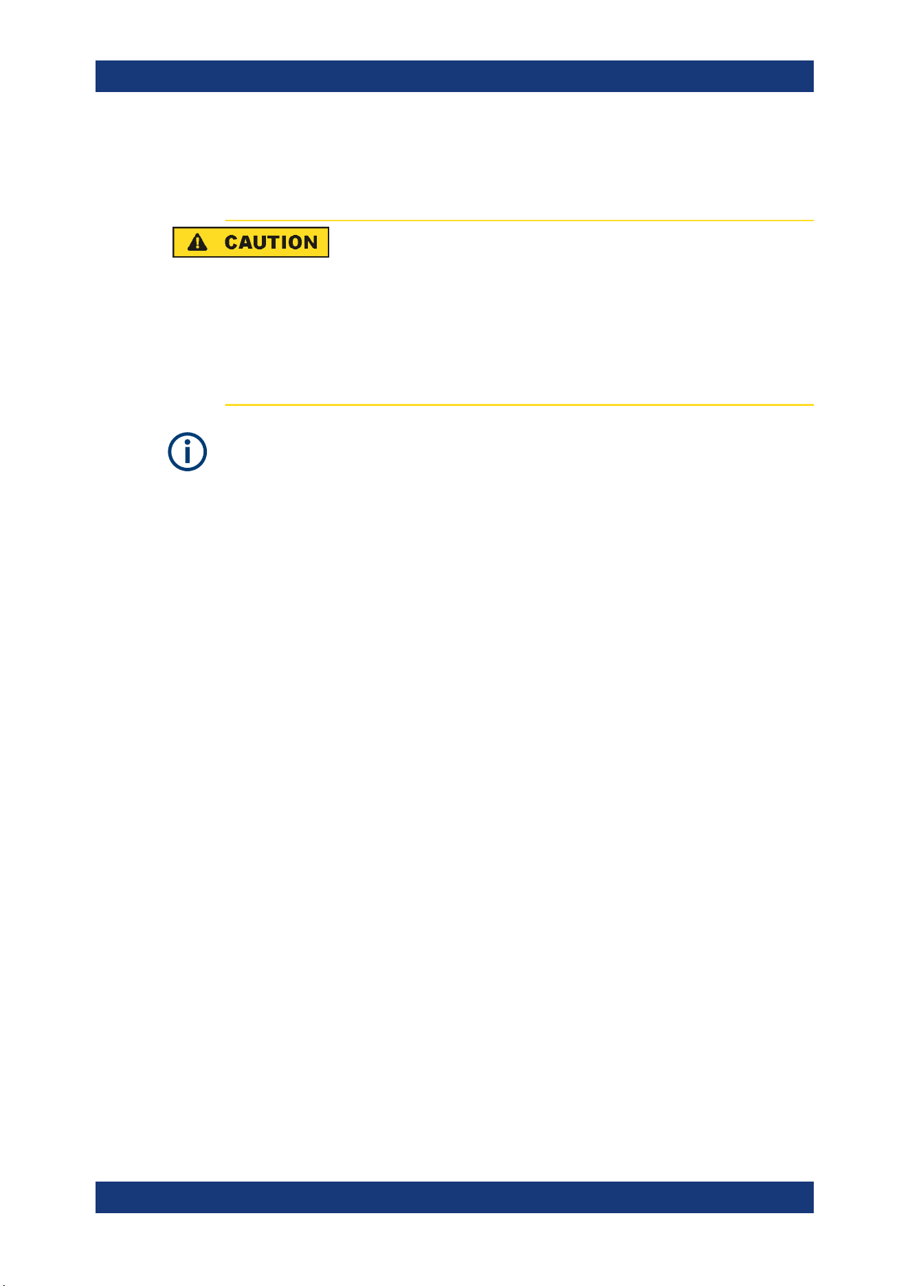
Instrument Functions
R&S
®
NGL200/NGM200
62User Manual 1178.8736.02 ─ 09
6.6 Trigger / Digital I/O
Digital I/O pins voltage rating
Do not exceed the maximum voltage rating of the Digital I/O pins when supplying vol-
tages to the pins.
The specified voltages are 0 V to 24 V for all output pins and 0 V to 15 V for all input
pins.
For more information, see the instrument datasheet (P/N: 5216.1057.32).
Instrument option
R&S NGL-K103 (P/N: 3652.6385.02) or R&S NGM-K103 (P/N: 3643.9904.02) option is
required for the Digital I/O signals.
Option is not required for "User Button" and "*TRG" trigger-in signals.
With an optional Digital I/O, you can apply a single trigger-in signal and control multiple
trigger-out signals on the instrument. These trigger-out signals can be used to perform
function such as triggering the data logger to record instrument when a channel output
is active or protection event is used to trigger the digital out pin, which in turn can be
used for fuse linking between two instruments.
The trigger system has two latency types: low latency and software latency. While low
latency triggers are executed faster, the software latency does not have additional
requirements.
The low latency actions are highlighted in bold (blue) and required to have same hard-
ware channel for trigger source and trigger target.
See
Figure 6-18 for an overview of the trigger IO system.
Trigger / Digital I/O
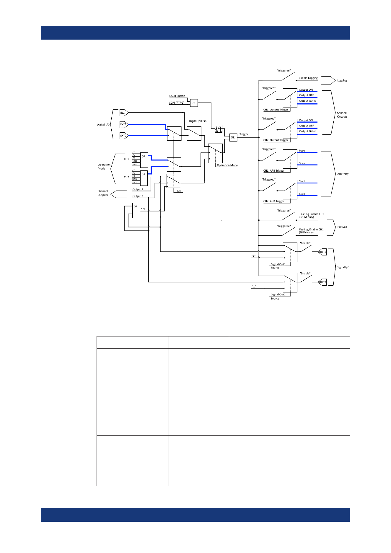
Instrument Functions
R&S
®
NGL200/NGM200
63User Manual 1178.8736.02 ─ 09
Figure 6-18: Overview of trigger IO system
Table 6-3: Trigger-in signals
Trigger-in parameters Source Descriptions
Ext. Trigger Ch1
Ext. Trigger Ch2
Digital In, pin 2 of Digi-
tal I/O connector
Digital In, pin 10 of Dig-
ital I/O connector
If detected, corresponding trigger-out parameters
are triggered.
The external trigger signal is low active (inverted
logic).
See Figure 6-18.
Digital I/O In1 Digital In, pin 3 of Digi-
tal I/O connector
If detected, corresponding trigger-out parameters
are triggered.
The Digital I/O In1 signal is low active (inverted
logic).
See Figure 6-18.
Output channel 1
Output channel 2
Any of the channels
Output If respective channel output is turned on, corre-
sponding trigger-out parameters are triggered.
If "Any" is selected, the corresponding trigger-out
parameters are triggered if any of the available
channels meet the condition.
See Figure 6-18.
Trigger / Digital I/O

Instrument Functions
R&S
®
NGL200/NGM200
64User Manual 1178.8736.02 ─ 09
Trigger-in parameters Source Descriptions
CC, CV, CR, Protection, Sink Operation Mode If respective channel operation modes, protection
event or sink mode is detected, corresponding
trigger-out parameters are triggered.
See Figure 6-18.
User button
*TRG
User button
SCPI command (*TRG)
remotely send to instru-
ment
If detected, corresponding trigger-out parameters
are triggered.
See Figure 6-18.
Table 6-4: Trigger-out signals
Trigger-out parameters Trigger conditions Descriptions
Output channel Output On
Output Off
Gated
If a trigger is detected, respective channel output
of the instrument turns on or off.
Digital Output Fault CC, CV, CR, Protection
and Sink, Output Off
If respective channel operation modes, protection
event or sink mode is detected, a trigger signal is
sent out at pin 11 of the Digital I/O connector.
If "Output Off" is selected, the "fault output" will be
active if the output of the selected channel is off.
See Figure 6-19.
Digital Output Out1 Trigger-in signal
Output On Ch1
If detected, a constant level trigger signal is sent
out at pin 4 of the Digital I/O connector.
If the pulse option is selected for the signal type,
an output pulse of 100 ms trigger signal is sent
out instead.
Digital Output Out2 Trigger-in signal
Output On Ch2
If detected, a constant level trigger signal is sent
out at pin 12 of the Digital I/O connector.
If the pulse option is selected, an output pulse of
100 ms trigger signal is sent out instead.
Logging Trigger-in signal If detected, the data logger starts recording the
instrument.
Arb Start triggered
Stop triggered
If a trigger is detected, respective channel starts
generating a complete arbitrary signal or steps
through the arbitrary signal for every trigger signal
detected.
The step time from the arbitrary signal is ignored
in the case when trigger condition is set as "Stop
triggered".
FastLog Trigger-in signal If detected, the FastLog module is enabled and
starts acquiring measurement data.
Trigger / Digital I/O
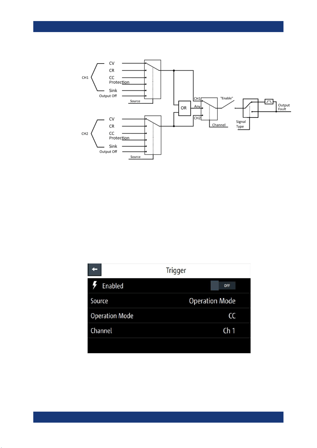
Instrument Functions
R&S
®
NGL200/NGM200
65User Manual 1178.8736.02 ─ 09
Figure 6-19: Digital output fault signal
Digital I/O connector
The Digital I/O connector is located below the GPIB connector, see
Chapter 4.2.1.2,
"Rear Panel"
, on page 22.
See
Figure 4-4 and Table 4-2 for the Digital I/O connector and pins layout.
1. Press [Settings] key.
The R&S NGL/NGM displays the device/channel menu window.
2. Select "Trigger" menu item to set the trigger-in parameter.
The R&S NGL/NGM displays the "Trigger" dialog.
Figure 6-20: An example if Operation Mode is selected as source
3. Select the "Source" to configure the trigger-in parameter.
See
Figure 6-18 for details of the trigger-in parameters.
Trigger / Digital I/O
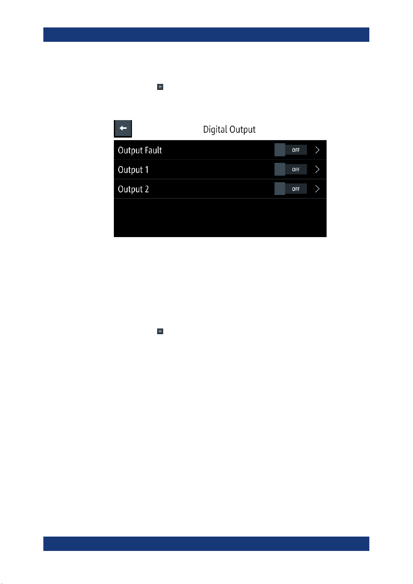
Instrument Functions
R&S
®
NGL200/NGM200
66User Manual 1178.8736.02 ─ 09
4. Select "Enable" and set it "On" to enable the trigger-in setting.
5.
Select "Back"
to go back to "Device" menu.
6. Select "Digital Output" to configure the trigger-out parameter.
The R&S NGL/NGM displays the "Digital Output" dialog.
Figure 6-21: Digital Out dialog
7. Depending on your requirements, select the digital output accordingly.
The two Digital I/O output pins OUT1 and OUT2 can be set directly by the SCPI
commands. See
DIO:OUTPut[:STATe] on page 158.
See also
Figure 6-18 for details of the trigger-out parameters.
8. Select the respective "Digital Output" menu items and set "On" to enable the trig-
ger-out parameters.
9.
Select "Back"
to go back to "Device" menu.
10. If "User Button" is set as a trigger-in signal, select "User Button" menu item.
The R&S NGL/NGM displays the "User Button" dialog.
See also
Chapter 6.8, "User Key", on page 71.
11. Select "User Button Action" and set as "Trigger".
The R&S NGL/NGM generates a trigger-in signal when user button key is pressed.
12. If "Logging" is set as a trigger-out signal, select "Logging" menu item.
The R&S NGL/NGM displays the "Logging" dialog.
See also
Chapter 6.10, "Data Logging", on page 73.
13. Select "Triggered" and set as "On".
The R&S NGL/NGM starts the data logging of the instrument when a trigger is
detected.
14. If "Arbitrary" is set as a trigger-out signal, select "Arbitrary" menu item from the
respective channel menu.
The R&S NGL/NGM displays the "Arbitrary" dialog.
See also
Chapter 6.7.1, "Arbitrary", on page 67.
Trigger / Digital I/O
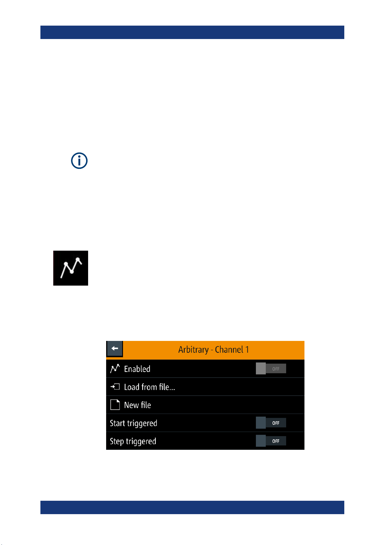
Instrument Functions
R&S
®
NGL200/NGM200
67User Manual 1178.8736.02 ─ 09
15. Depending on your requirement, select "Start triggered" or "Step triggered" menu
item and set "On".
The R&S NGL/NGM starts or steps through the arbitrary signal when a trigger is
detected.
6.7 Advanced Features
Arbitrary function
If Arbitrary function of a selected channel is enabled, the respective channel voltage,
current setting and safety limit settings are disabled.
See Chapter 6.1, "Setting the Channels Voltage and Current", on page 44.
The Arbitrary and Ramp are two functions which can be used to control the waveform
of voltage and current output.
6.7.1 Arbitrary
The Arbitrary function allows you to generate freely programmable waveforms which
can be reproduced within the
Safety Limits for voltage and current.
1. Press [Settings] key.
The R&S NGL/NGM displays the device/channel menu window.
2. Select the required channel tab to configure Arbitrary function.
The R&S NGL/NGM displays the selected channel menu.
3. Select "Arbitrary" from the menu.
The R&S NGL/NGM displays the "Arbitrary" dialog.
Figure 6-22: Select source and file location
Advanced Features
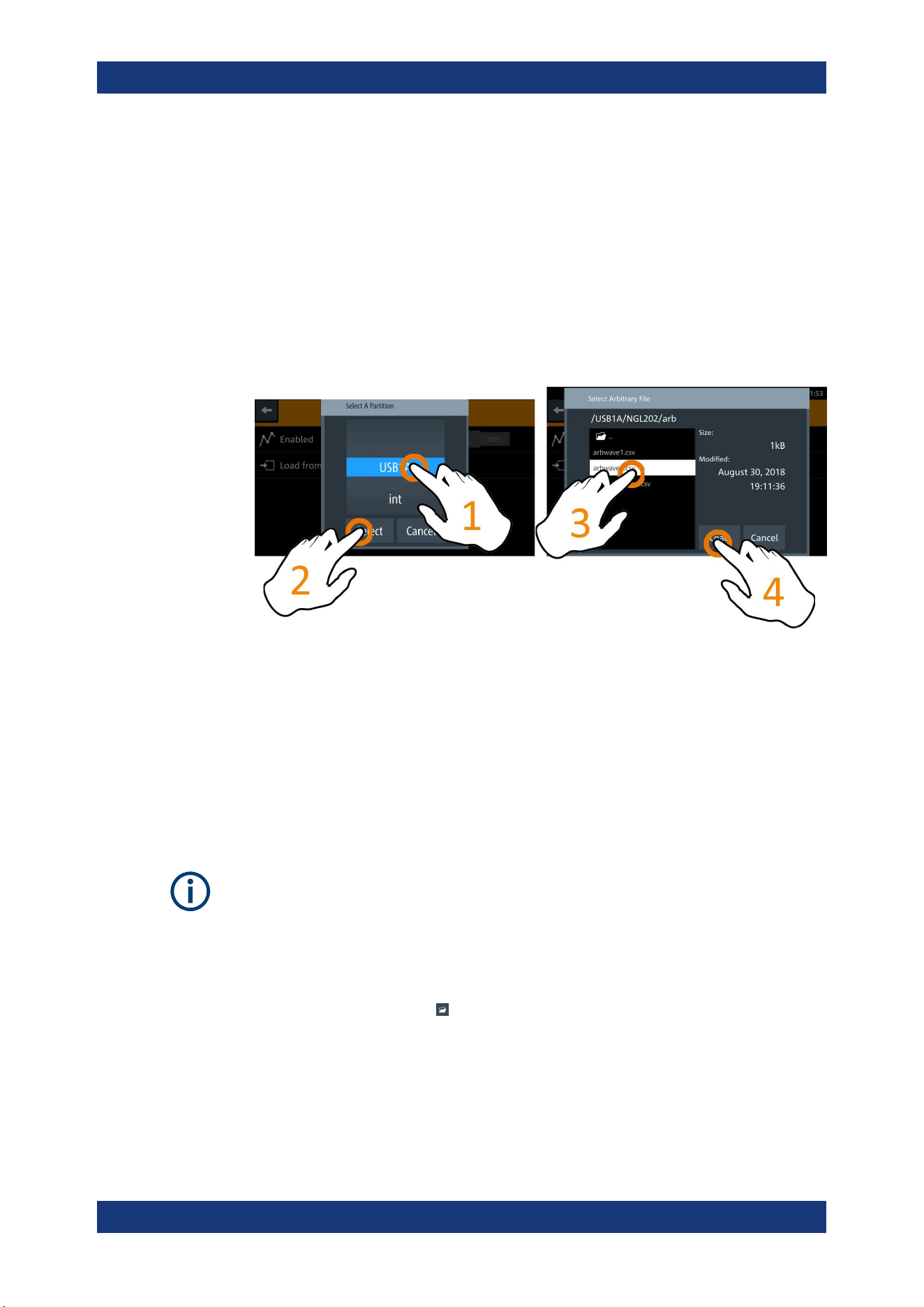
Instrument Functions
R&S
®
NGL200/NGM200
68User Manual 1178.8736.02 ─ 09
4. Activates the "Enabled" menu item.
The R&S NGL/NGM enables the Arbitrary function and displays the "Arbitrary" icon
on the selected channel status bar information.
5. Select "Load from file.." to load the arbitrary file.
6. Select the required source and file location.
Alternatively, select "New file" to edit a new arbitrary file. The R&S NGL/NGM
opens the
arbitrary editor dialog to edit the arbitrary file.
7. Select "Load" to load the selected file.
The R&S NGL/NGM loads the selected arbitrary file.
8. Applicable only with R&S NGL-K103 or R&S NGM-K103, Digital Output option.
See Chapter 6.6, "Trigger / Digital I/O", on page 62.
Activate "Start triggered" or "Step triggered" if the arbitrary function is executed
under triggered condition.
● "Start triggered": If triggered, the complete arbitrary function is executed.
● "Step triggered": If triggered, every arbitrary step needs a trigger signal to exe-
cute (step time from "Arb Editor" is ignored).
Arbitrary editor
Interpolation flag
After execution of all repetition cycles, the last interpolation flag is ignored. See
Fig-
ure 6-22.
The "Arb Editor" dialog allows you to edit the arbitrary profile ("Voltage", "Current",
"Time", "Interpolate" status, "Rep." and "End Behavior"). To view or open the list of
available arbitrary files, select
to open the arbitrary file.
Advanced Features
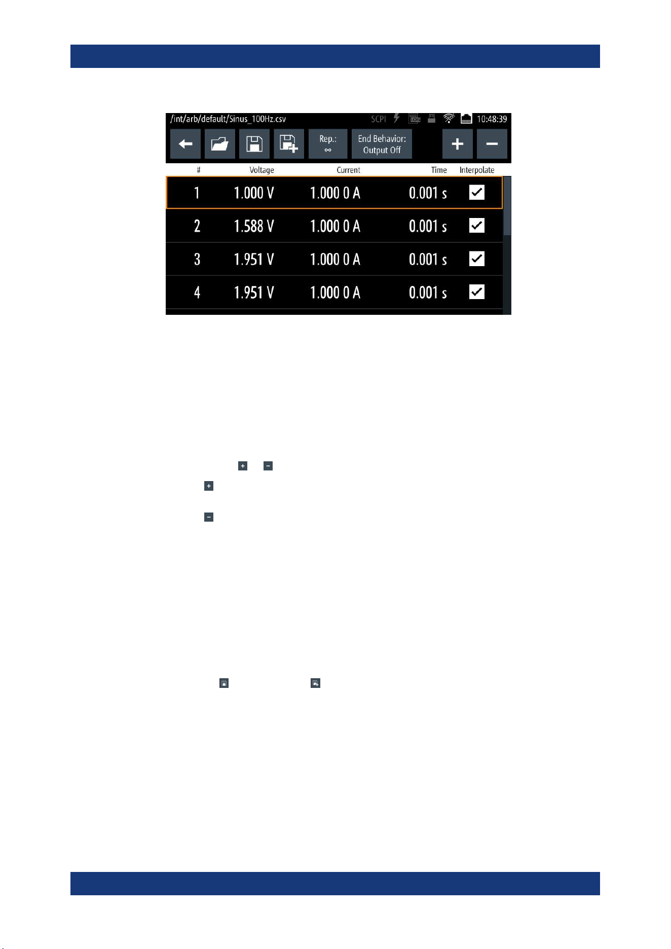
Instrument Functions
R&S
®
NGL200/NGM200
69User Manual 1178.8736.02 ─ 09
Figure 6-23: Arbitrary editor dialog
1. Configure the "Arb Editor" with the required voltage, current and duration.
The R&S NGL/NGM displays the on-screen keypad for data entry.
2. Confirm values with the unit keys.
3. Select the interpolation checkbox to toggle on/off the interpolation function on the
arbitrary data.
4.
Select the
or icon to add or delete the arbitrary data from the dialog.
●
: A new row of data is added at the end of the table. It is initially filled with the
data of the currently selected row.
●
: Removes the currently selected row from the table.
5. Set the "Rep" to configure repetition cycle for the arbitrary data.
By default, the repetition cycle is set to infinity.
6. Set the "End Behavior" to handle the way to end the automation of the Arbitrary
function.
● "Off": The output of the selected channel is turned off after performing the Arbi-
trary function.
● "Hold": The last voltage and current values remains at the output terminal of
the instrument.
7.
Select
(existing file) or (new file) to save the arbitrary data.
The R&S NGL/NGM displays a popup message to show that file saved success-
fully.
Advanced Features
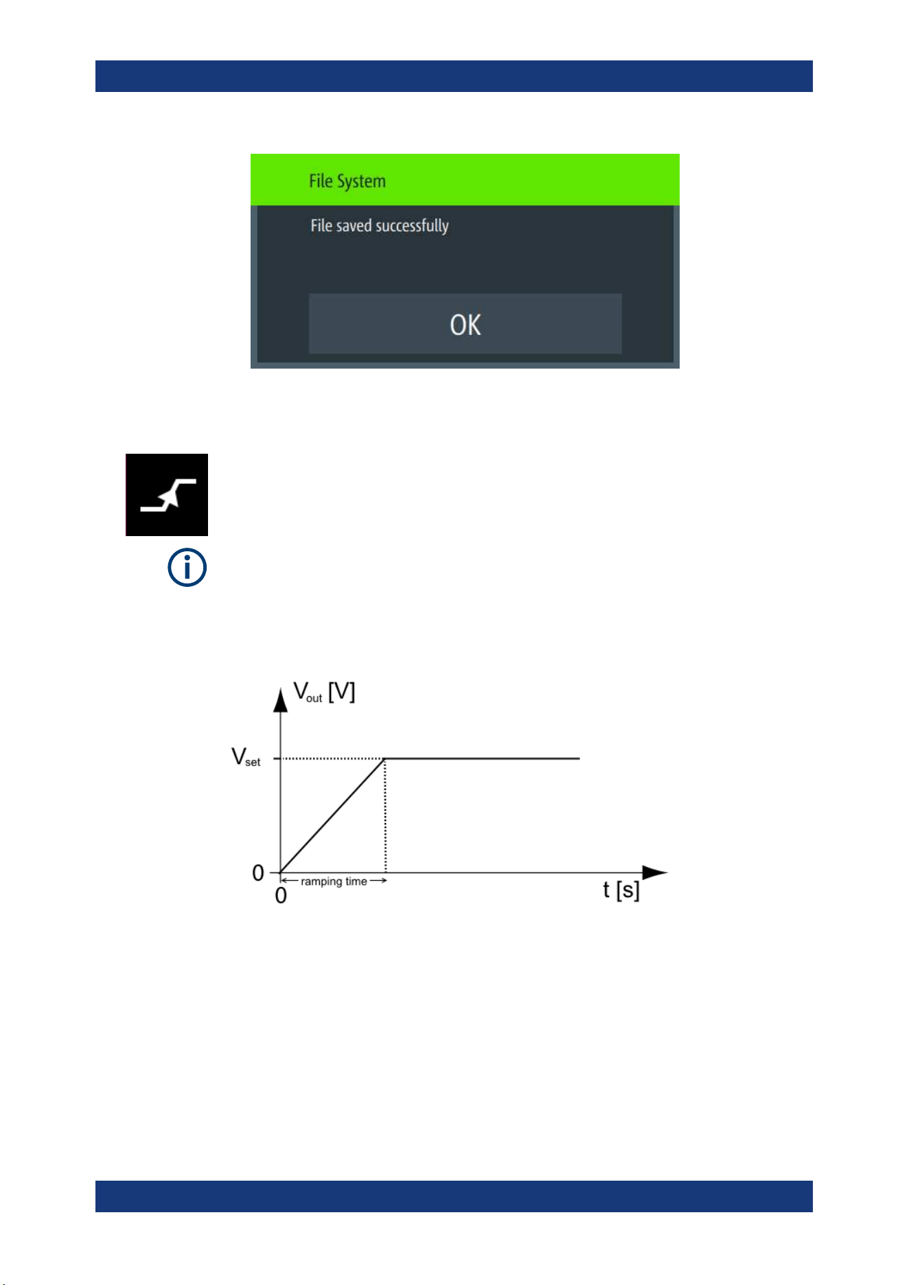
Instrument Functions
R&S
®
NGL200/NGM200
70User Manual 1178.8736.02 ─ 09
6.7.2 Ramp
The Ramp function configures a constant rise of supply voltage within a set time frame.
The output voltage can be increased continuously within a 10 ms to 10 s time frame.
Each channel has an independent ramp configuration. See
Figure 6-24.
Internal resistance
The internal resistance control is only applied after the ramp is processed until the con-
figured target value is reached.
See
Chapter 6.2.1, "Set Constant Resistance", on page 46.
Figure 6-24: Ramping voltage output
1. Press [Settings] key.
The R&S NGL/NGM displays the device/channel menu window.
2. Select the required channel tab to configure Ramp function.
The R&S NGL/NGM displays the selected channel menu.
3. Select "Ramp" from the menu.
The R&S NGL/NGM displays the "Ramp" dialog.
Advanced Features

Instrument Functions
R&S
®
NGL200/NGM200
71User Manual 1178.8736.02 ─ 09
Figure 6-25: Ramp dialog
4. Activate the "Enabled" menu item.
The R&S NGL/NGM enables the Ramp function and displays the "Ramp" icon on
the selected channel status bar information.
5. Set the required "Ramp Time".
The R&S NGL/NGM displays the on-screen keypad to set the value.
6. Confirm value with the unit key.
6.8 User Key
The R&S NGL/NGM allows you to configure the user action for one of the following
functions:
●
Screenshot image from instrument
●
Instrument trigger function
●
Data logging
●
Reset statistic (see index 1, 2, 3 of
Figure 5-6)
●
Enable/Disable touchscreen function
1. Press [Settings] key.
The R&S NGL/NGM displays the device/channel menu window.
2. Select the "Device" menu tab to configure user action.
The R&S NGL/NGM displays the device menu.
3. Select "User Button" from the menu.
Alternatively, long-press on the [*] key to configure the user button action.
The R&S NGL/NGM displays the "User Button" dialog.
User Key
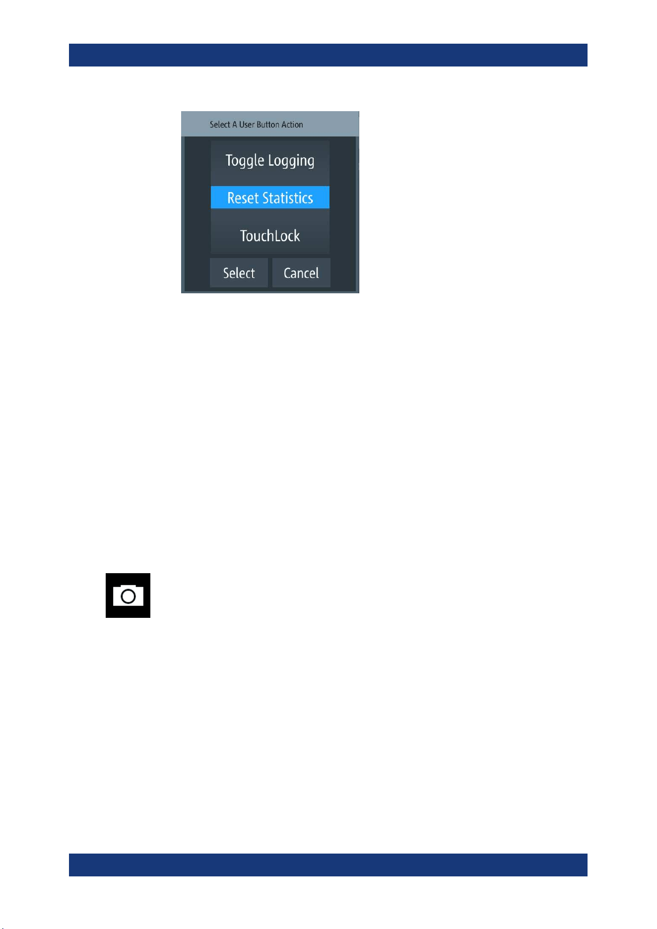
Instrument Functions
R&S
®
NGL200/NGM200
72User Manual 1178.8736.02 ─ 09
Figure 6-26: User button action
4. Select the "User Button Action" to configure the user action.
The R&S NGL/NGM displays a dialog to configure the user action.
5. Select the required user action.
● "Screenshot": Capture the current screen image of the instrument
● "Trigger": User key is used to activate the instrument trigger function
● "Toggle Logging": Enable/Disable the data logger function
● "Reset Statistics": Reset sample count, energy result, power, voltage and cur-
rent values
● "TouchLock": Enable/Disable the touchscreen function of the instrument
6. Select "Select" to confirm the action.
6.9 Screenshot
With screenshot, you can capture image easily from the instrument. The images can
be stored in the USB stick or internal memory of the instrument. By default, the screen
images are stored in the USB device under the target folder.
1. Press [Settings] key.
The R&S NGL/NGM displays the device/channel menu window.
2. Select the "Device" tab to configure screenshot file location.
The R&S NGL/NGM displays the device menu.
3. Select "Screenshot" from the menu.
The R&S NGL/NGM displays the "Screenshot" dialog.
Screenshot
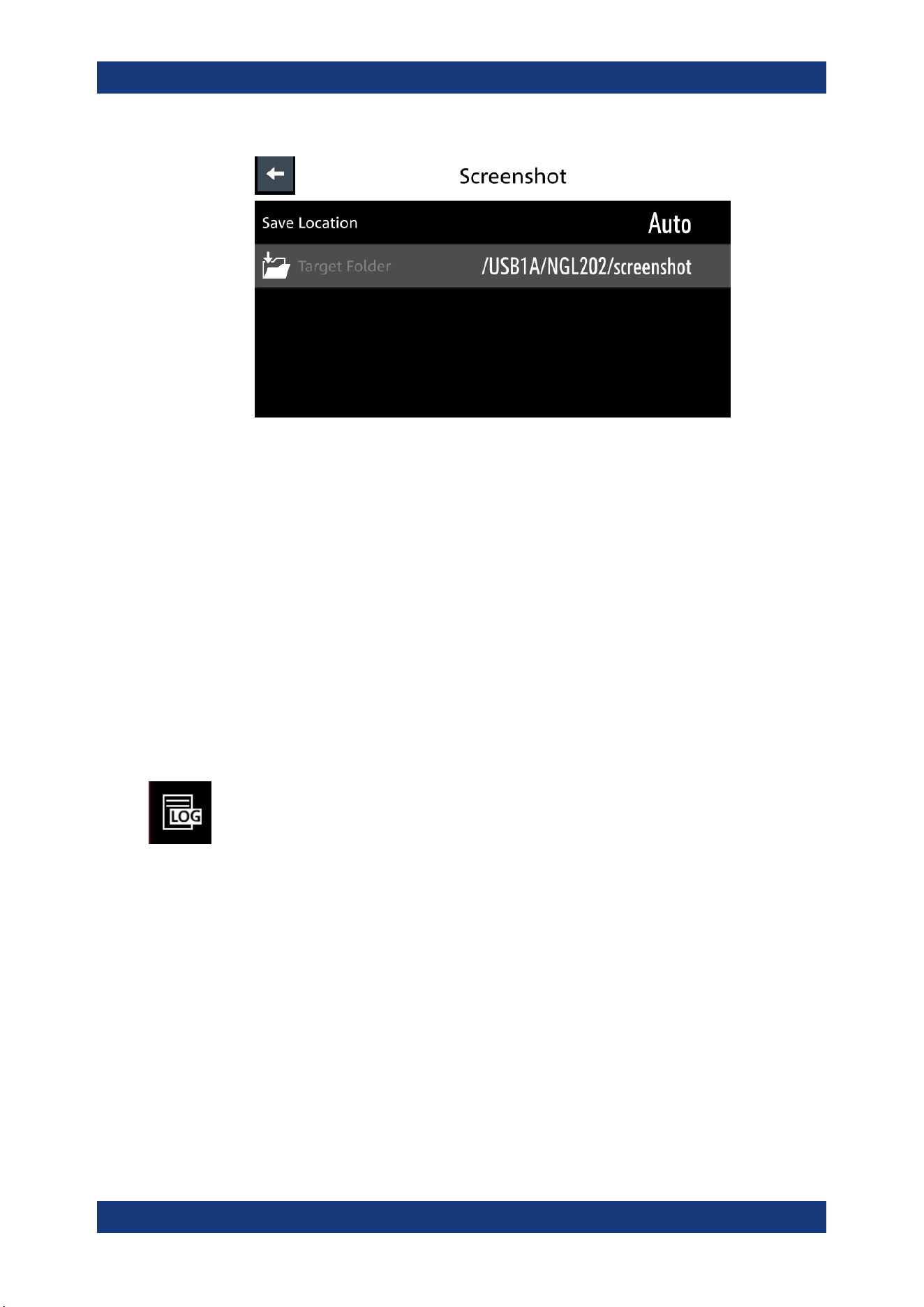
Instrument Functions
R&S
®
NGL200/NGM200
73User Manual 1178.8736.02 ─ 09
Figure 6-27: Screenshot dialog
4. Select the "Save Location" to configure the screenshot file location.
● "Auto": Target folder is set to default file location:
– With USB stick detected:
/USB1A/NGL202/screenshot for NGL model
/USB1A/NGM202/screenshot for NGM model
– Without USB stick detected:
/int/screenshot
● "Manual": Choice of target folder.
5. Select the required save location.
6.10 Data Logging
When data logging is activated, the R&S NGL/NGM records the voltage, current and
power data and stores it in the predefined target folder. The measurement data can be
stored on the USB stick or in the instrument internal memory location.
1. Press [Settings] key.
The R&S NGL/NGM displays the device/channel menu window.
2. Select the "Device" tab to configure data logger.
The R&S NGL/NGM displays the device menu.
3. Select "Logging" menu item from the menu.
The R&S NGL/NGM displays the "Logging" dialog.
Data Logging
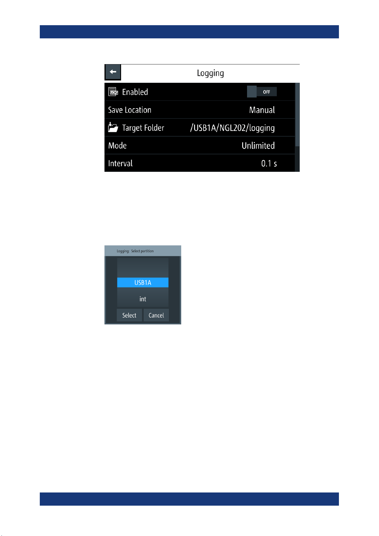
Instrument Functions
R&S
®
NGL200/NGM200
74User Manual 1178.8736.02 ─ 09
4. Select the "Save Location" menu item to select the predefined target folder for data
logger.
● "Auto": "Target Folder" is auto-selected.
If no USB stick is detected, "Target Folder" is set to internal memory ("int") par-
tition. By default, "USB1A" partition is selected.
● "Manual": Choice of "Target Folder".
Selection is possible only if USB stick is detected.
Figure 6-28: Target folder dialog
5. Set the required "Target Folder".
6. Select "Mode" to set logging duration.
● "Duration": Time taken for data logging with duration and time interval setting.
● "Span": Time taken for data logging with start time, time interval and duration
setting
● "Unlimited": Data logging with time interval setting. The data logging continuous
until function is deactivated.
● "Count": Data logging with number of counts and time interval setting
7. Depending on the selected mode, configure the required settings for the data log-
ging duration.
8. Activate the "Enabled" menu item.
Data Logging

Instrument Functions
R&S
®
NGL200/NGM200
75User Manual 1178.8736.02 ─ 09
The R&S NGL/NGM activates the logging and disables the settings for file saved
location and logging mode settings.
9. Applicable only with R&S NGL-K103, activate the "Triggered" menu item if data
logging is required under triggered conditions.
If activated, the R&S NGL/NGM executes the data logging if a trigger event occurs.
See
Figure 6-18 and Figure 6-26.
10. Configure the "CSV Settings".
See Chapter 6.12, "CSV Settings", on page 76.
6.11 FastLog
Available only with the NGM models.
A USB stick with a minimum of 10MB/s continuous write speed is recommended for
data storage.
The FastLog can write the measurement data (votage/current) either to the USB
device or to a SCPI client. In SCPI mode the client is required to be connected to the
R&S NGM before "FastLog" is enabled
"FastLog" is a much faster data logging for voltage and current measurements. This
fast logging features the benefit to capture short peak changes in voltage and/or cur-
rent measurements which is particular useful in the measuring of low energy device,
e.g. IoT products.
Refer to the data specification for the maximum data logging and resolution for NGM
models.
1. Press [Settings] key.
The R&S NGM displays the device/channel menu window.
2. Select the required channel tab to configure "FastLog" function.
The R&S NGM displays the selected channel menu.
3. Select "FastLog" menu item from the menu.
The R&S NGM displays the "FastLog" dialog.
FastLog
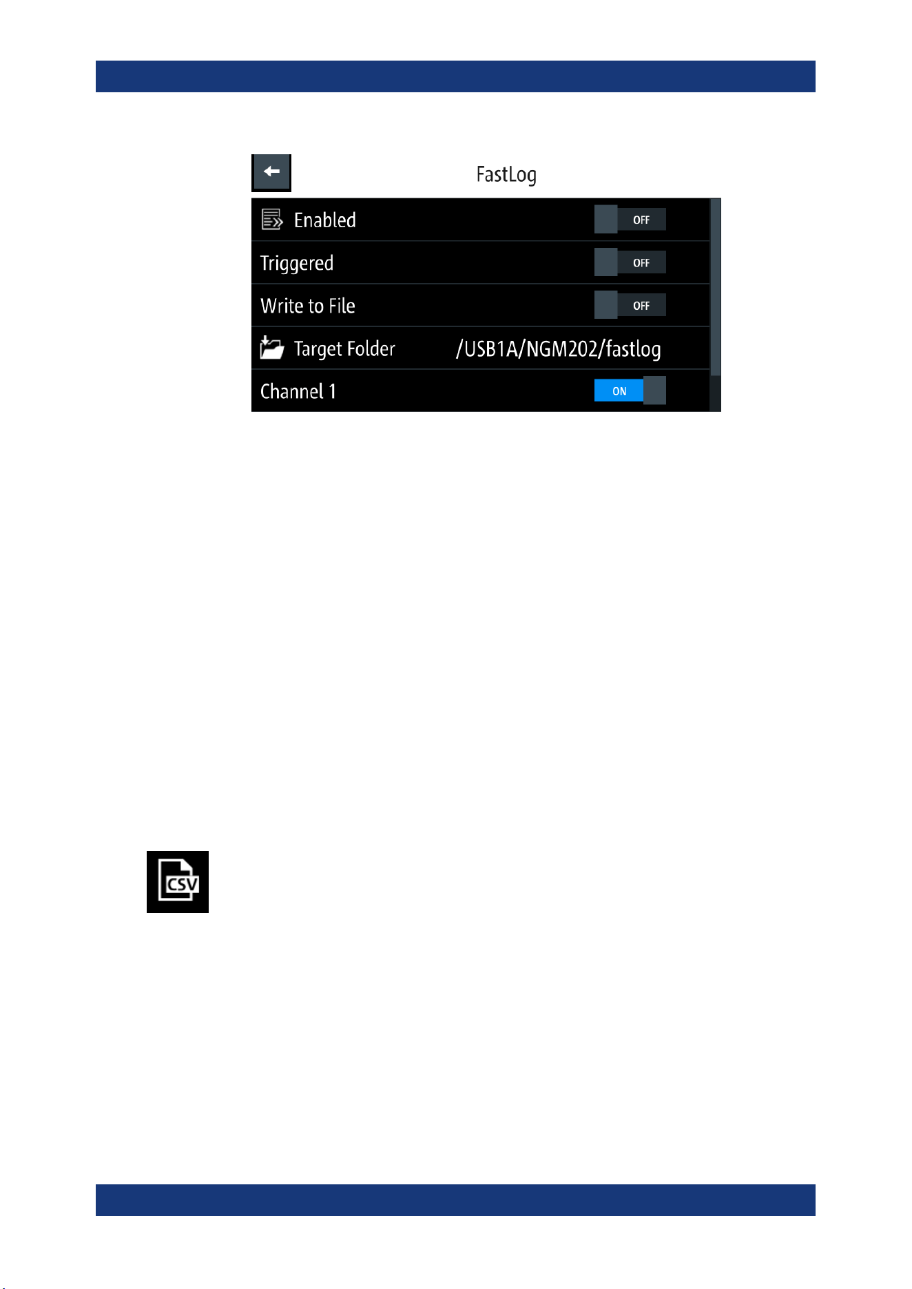
Instrument Functions
R&S
®
NGL200/NGM200
76User Manual 1178.8736.02 ─ 09
4. Select "Enabled" to activate the "FastLog" function.
The R&S NGM starts the fast logging and displays the "Fast Logging" icon at the
device status bar information.
5. Select "Triggered" to "ON" if you want "FastLog" to be enabled by a trigger event.
6. Select "Write to USB" if you want to save the measurements data to a binary file.
The file is saved to the directory specified in the "Target Folder". The R&S NGM
creates a file for each channel and logs the measurement data to the binary file.
7. Select "Write to SCPI" to transfer the data to a SCPI client.
Note: It is possible to select a sample rate of 500 kS/s on both channels at the
same time.
If "FastLog" on one channel is activated at 500 kS/s, the other channel is blocked.
If both channels are to be activated by a trigger, it is checked whether the sum of
the sample rates > 500 kS/s. If this is the case, the operation is aborted with an
error message and none of the channels are switched on.
6.12 CSV Settings
A CSV file stores tabular data (numbers and text) in plain text. Each line of the file is a
data record and each record consists of one or more fields, separated by a file delim-
iter. The "CSV Settings" provides you ways to format the fields that are stored in the
data logging. See
Figure 6-29.
CSV Settings
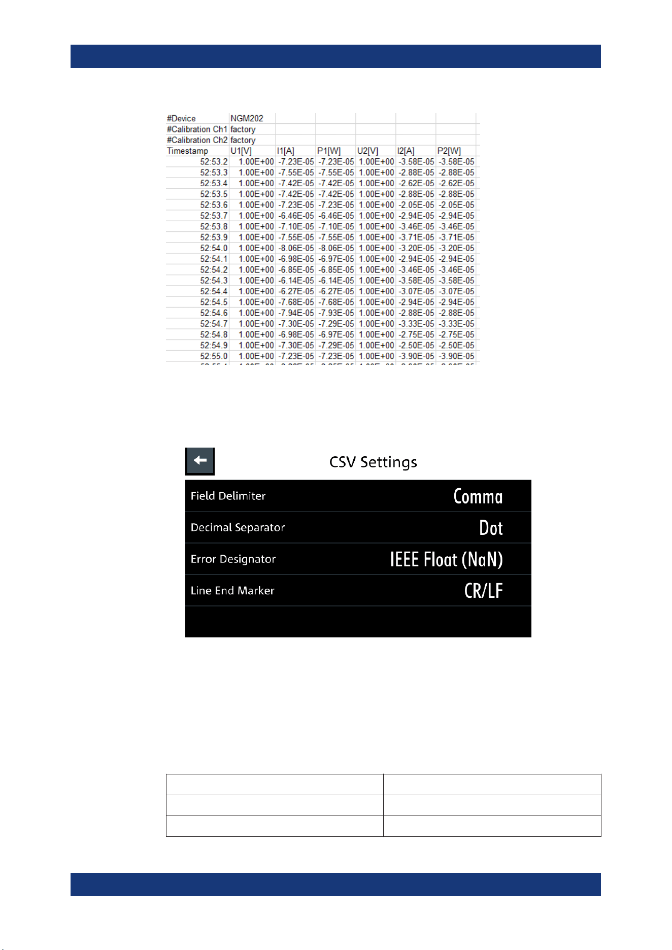
Instrument Functions
R&S
®
NGL200/NGM200
77User Manual 1178.8736.02 ─ 09
Figure 6-29: Sample of data logging
1. Select "CSV Settings" from "Device" menu.
The R&S NGL/NGM displays the "CSV Settings" dialog.
Figure 6-30: CSV settings dialog
2. Set the required CSV parameters.
The R&S NGL/NGM displays the respective dialog to set the CSV parameters.
See
Table 6-5.
3. Select "Set" to confirm the value.
Table 6-5: CSV settings
CSV settings Selective fields in the dialog
"Field Delimiter" "Comma", "Semicolon"
"Decimal Separator" "Dot", "Comma"
CSV Settings
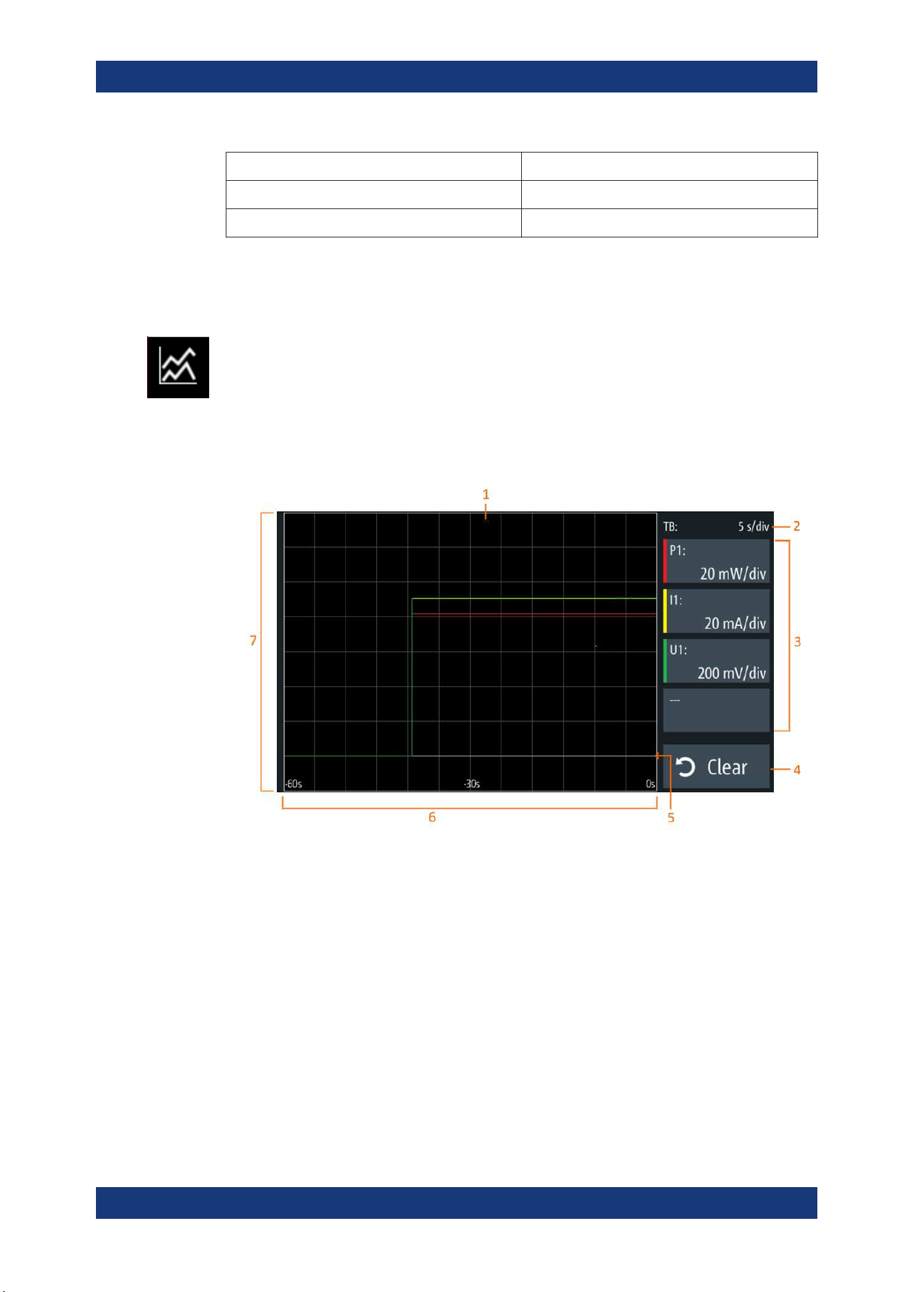
Instrument Functions
R&S
®
NGL200/NGM200
78User Manual 1178.8736.02 ─ 09
CSV settings Selective fields in the dialog
"Error Designator" "IEE Float (NaN)", "Empty"
"Line End Marker" "CR/LF", "LF"
6.13 Graphical View Window
The graphical view measurement is a time-based measurement that allows you to vis-
ualize measurements on available data sources.
The graph illustrated below shows the output of voltage "U1" 0.9 V, current "I1" 90 mA
at channel 1 with output power of "P1" 81 mW from 39 seconds ago. Each measure-
ment trace is represented with an individual color.
The time-based scale is fixed with a time duration display up to the last 60 seconds.
Figure 6-31: Graphical view window
1 = Display window for measurement
2 = Time axis scale fixed at 5 s/div
3 = Configuration slot for measurement
4 = Reset measurements in display window
5 = Zero-origin of the graph
6 = Time axis
7 = Measurement axis
1. Long-press on the [Settings] key or the "Settings" button in
Chapter 5.1.2, "Chan-
nel Display Area"
, on page 32.
The R&S NGL/NGM displays the graphical view window. See Figure 6-31.
2. Alternatively, press [Settings] > device menu > "Graphical View" to access graphi-
cal view window.
Graphical View Window
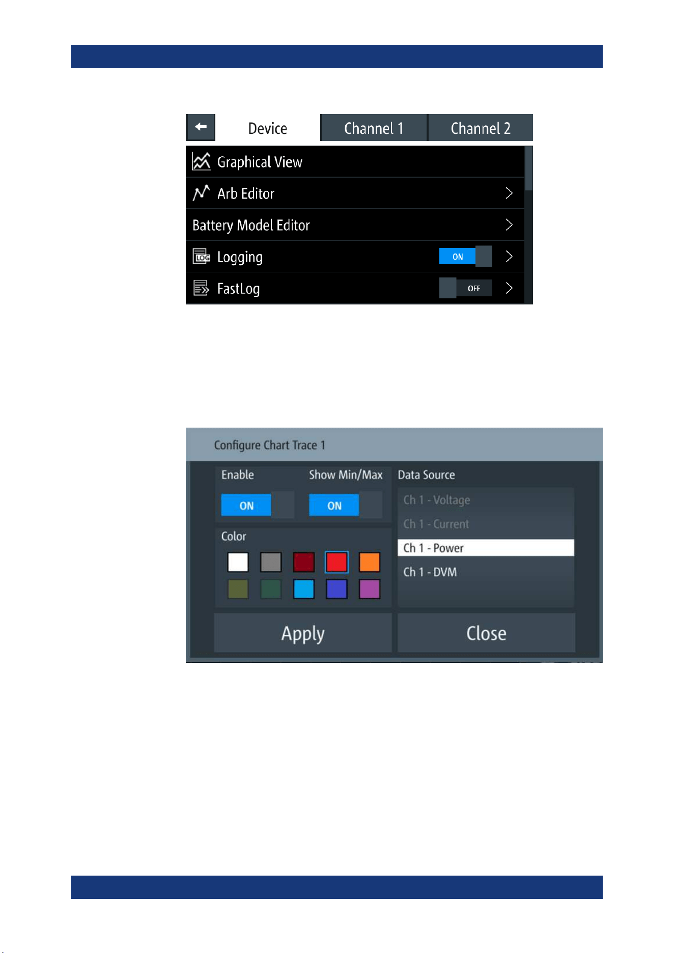
Instrument Functions
R&S
®
NGL200/NGM200
79User Manual 1178.8736.02 ─ 09
Figure 6-32: Device menu
3. Select any of the configuration slots to configure the measurement parameters.
Note: For NGM models only, the DVM measurement must be enabled in the
respective channels for the measurement to be available in the configuration dia-
log.
The R&S NGL/NGM displays the configuration dialog.
4. Select the available "Data Source" for configuration.
The dimmed "Data Source" is in use and is not configurable.
5. Set "Enable" to activate the selected "Data Source" for measurement.
6. Select the available "Color" to configure the "Data Source" measurement trace.
7. Set "Show Min/Max" to "ON" to display the minimum and maximum value of the
selected "Data Source".
Graphical View Window
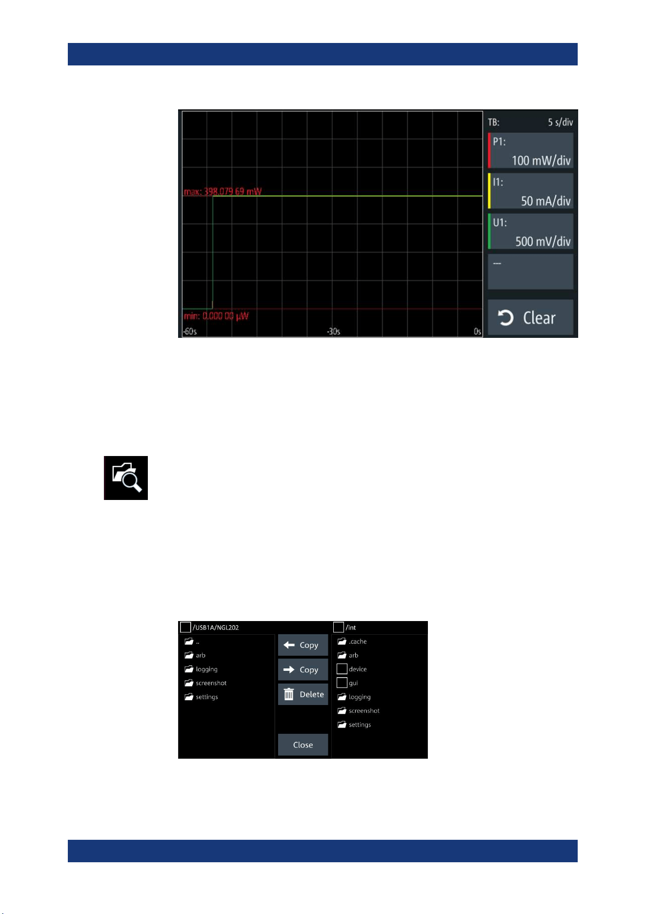
Instrument Functions
R&S
®
NGL200/NGM200
80User Manual 1178.8736.02 ─ 09
8. Select "Apply" to confirm the configuration.
9. Select "Close" to exit configuration dialog.
6.14 File Manager
The "File Manager" provides file transfer functions between USB stick and internal
memory of the instrument. You can copy and delete files in both USB stick and internal
memory of the instrument.
1. Press [Settings] key.
The R&S NGL/NGM displays the device/channel menu window.
2. Select the "Device" tab to configure file settings for store and recall function.
The R&S NGL/NGM displays the device menu.
3. Select "File Manager" from the menu.
The R&S NGL/NGM displays the file manager dialog.
Figure 6-33: File manager dialog
File Manager
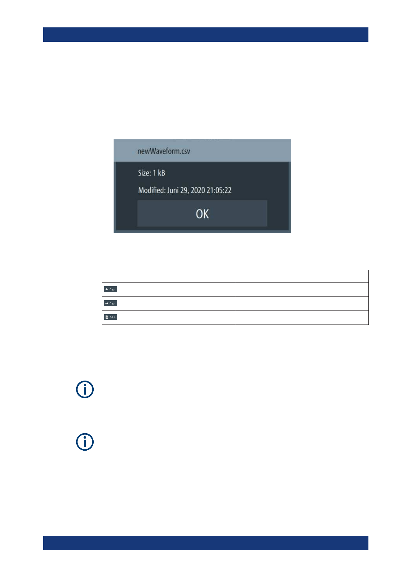
Instrument Functions
R&S
®
NGL200/NGM200
81User Manual 1178.8736.02 ─ 09
4. Select the file that you want to copy or delete.
5. Select the required action in the file manager dialog.
See Table 6-6.
6. To view the selected file information, long-press on the selected filename in the file
manager dialog.
A pop-up message box is displayed with the file information.
Figure 6-34: File information
Table 6-6: File manager action
Action Description
Copy from internal memory to USB.
Copy from USB to internal memory.
Delete the selected file.
6.15 Store and Recall
Upon power-up, the instrument loads the last stored settings from internal memory
location. Auto saved parameters are also applied during startup.
The R&S NGL/NGM output states of all channels (Ch1, Ch2) are disabled when the
recall function is activated.
Auto saved instrument settings
Auto saved of the instrument settings is applied when any of the following parameters
are changed:
●
Chapter 6.17, "General Instrument Settings", on page 90
●
USB connection mode
●
Ethernet settings
Store and Recall
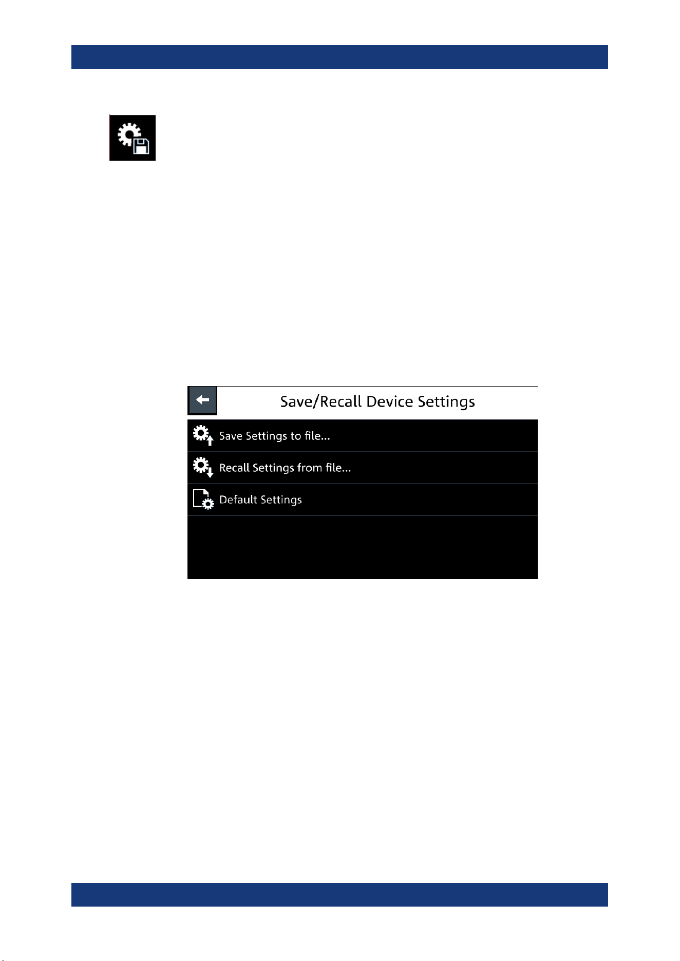
Instrument Functions
R&S
®
NGL200/NGM200
82User Manual 1178.8736.02 ─ 09
In addition of the auto saved instrument settings, the following instrument settings are
stored or recalled in the internal memory:
●
Set voltage and current level
●
Settings in the Protection Function, Safety Limits
●
Arbitrary settings, Ramp settings
●
User button key function
●
Data Logging settings
●
GPIB Address
1. Press [Settings] key.
The R&S NGL/NGM displays the device/channel menu window.
2. Select the "Device" tab to configure file settings for store and recall function.
The R&S NGL/NGM displays the device menu.
3. Select "Save/Recall Device Settings".
The R&S NGL/NGM loads the "Save/Recall Device Settings" dialog.
Figure 6-35: Save/Recall device settings dialog
4. Select "Save Settings to file..." to save current instrument settings.
The R&S NGL/NGM opens a dialog to select source and file location.
You can save to existing file or create a file for saving.
5. Set the source and file location.
The R&S NGL/NGM saves the current instrument settings.
6. Similar, you can select "Recall Settings from file..." to load instrument settings.
The R&S NGL/NGM opens a dialog to select source and file location.
7. Set the source and file location.
The R&S NGL/NGM resets the instrument with the loaded instrument settings.
To reset the instrument settings to factory default:
1. Select "Default Settings" from the "Save/Recall Device Settings" dialog.
Store and Recall
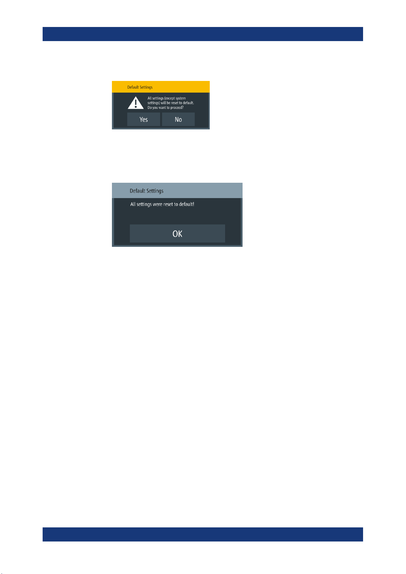
Instrument Functions
R&S
®
NGL200/NGM200
83User Manual 1178.8736.02 ─ 09
The R&S NGL/NGM displays a popup message.
2. Select "Yes" to overwrite instrument settings to factory default.
The R&S NGL/NGM resets current instrument settings to factory default.
3. The R&S NGL/NGM displays a popup message to show that all settings are reset
to factory default.
6.16 Interfaces
There are various of ways how the R&S NGL/NGM can be remotely accessed and
controlled.
1. Press [Settings] key.
The R&S NGL/NGM displays the device/channel menu window.
2. Select the "Device" tab to configure network connection.
The R&S NGL/NGM displays the device menu.
3. Select "Interfaces".
The R&S NGL/NGM displays the "Interfaces" dialog.
Interfaces
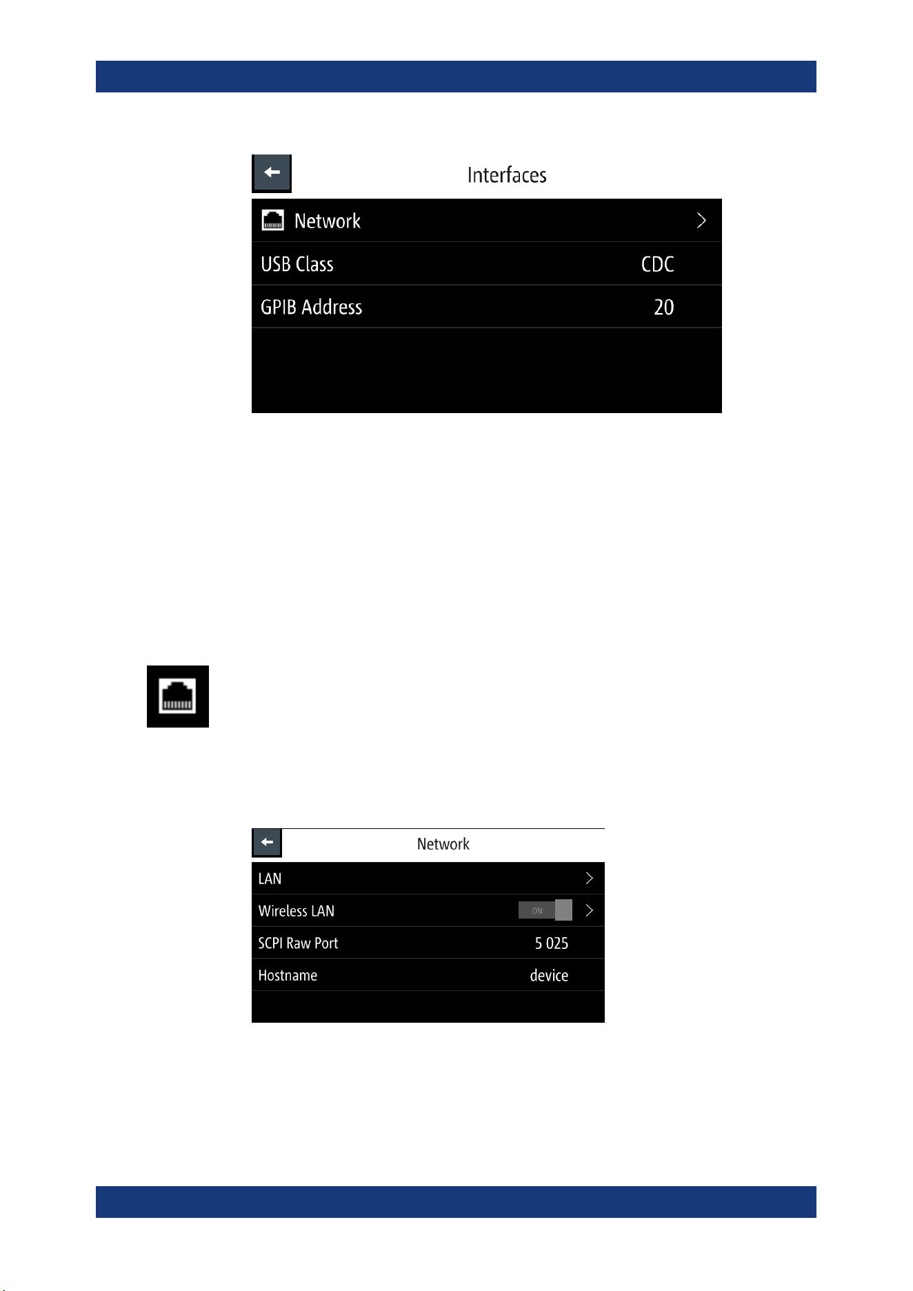
Instrument Functions
R&S
®
NGL200/NGM200
84User Manual 1178.8736.02 ─ 09
Figure 6-36: Interfaces dialog
4. Select the connected interface (
Network, USB Class or GPIB Address) to configure
the necessary parameters required.
●
Network Connection................................................................................................84
●
USB Connection......................................................................................................88
●
GPIB Address......................................................................................................... 89
6.16.1 Network Connection
There are two methods to establish a local area network (LAN) connection with the
R&S NGL/NGM for remote control operation.
●
LAN
●
Wireless LAN
1. Select "Network" from the Figure 6-36.
The R&S NGL/NGM displays the "Network" dialog.
Figure 6-37: Network dialog
2. Set the required "SCPI Raw Port" and "Hostname".
Interfaces
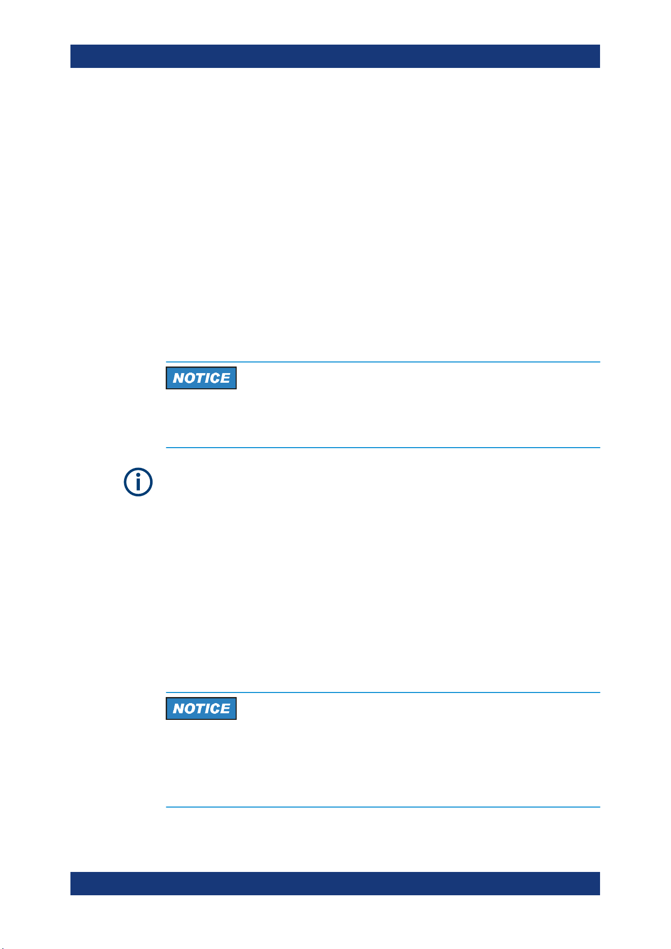
Instrument Functions
R&S
®
NGL200/NGM200
85User Manual 1178.8736.02 ─ 09
The R&S NGL/NGM displays the on-screen keypad to enter the port number and
hostname.
● "SCPI Raw Port": A port number used to open a raw TCP/IP connection to
send raw SCPI commands to the instrument
● "Hostname": The name assigned to the instrument used to identify it in the net-
work
When the connection is available, the network icon is highlighted in white on the device
status bar information.
6.16.1.1 LAN Connection
The R&S NGL/NGM is equipped with a network interface and can be connected to an
Ethernet LAN (local area network). A LAN connection is necessary for remote control
of the instrument, and for access from a computer using a web browser.
Risk of network failure
Before connecting the instrument to the network or configuring the network, consult
your network administrator. Errors may affect the entire network.
To establish a network connection, connect a commercial RJ-45 cable to the LAN port
of the instrument and to a PC or network switch.
Depending on the network capacities, the TCP/IP address information for the instru-
ment can be obtained in different ways.
●
If the network supports dynamic TCP/IP configuration using the Dynamic Host
Configuration Protocol (DHCP), and a DHCP server is available, all address infor-
mation can be assigned automatically.
●
Otherwise, the address must be set manually. Automatic Private IP Addressing
(APIPA) is not supported.
By default, the instrument is configured to use dynamic TCP/IP configuration and
obtain all address information automatically. This means that it is safe to establish a
physical connection to the LAN without any previous instrument configuration.
Risk of network errors
Connection errors can affect the entire network. If your network does not support
DHCP, or if you choose to disable dynamic TCP/IP configuration, you must assign valid
address information before connecting the instrument to the LAN. Contact your net-
work administrator to obtain a valid IP address.
Interfaces
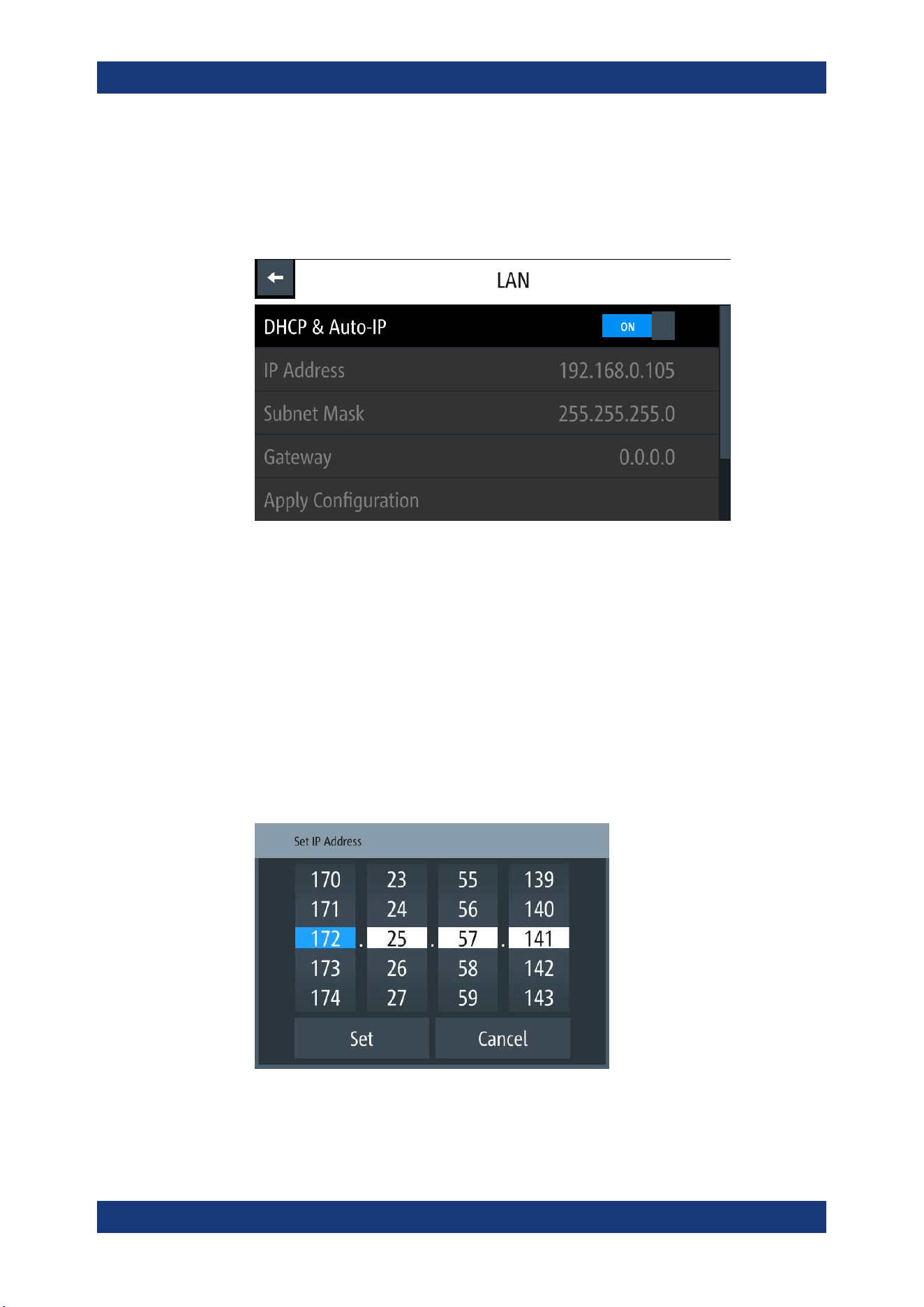
Instrument Functions
R&S
®
NGL200/NGM200
86User Manual 1178.8736.02 ─ 09
1. Connect the LAN cable to the LAN connector at the rear panel of the instrument.
2. Select "LAN" to set LAN connection.
The R&S NGL/NGM displays the "LAN" dialog.
Note: The "MAC Address" is fixed.
Figure 6-38: Ethernet settings dialog
3. Set the "DHCP & Auto-IP".
● "ON": Enables DHCP for automatic network parameter distribution and shows
the values of the IP Address. By default, the instrument is configured to use
dynamic configuration and obtain all address information automatically.
● "OFF": If the network does not support dynamic host configuration protocol
(DHCP). The addresses must be set manually.
4. Set the required DHCP mode.
If DHCP mode is set "OFF", the following "Ethernet Settings" are required.
5. Configure the "IP Address", "Subnet Mask" and "Gateway".
The R&S NGL/NGM displays the IP dialog for configuration.
Figure 6-39: IP dialog
6. Set the required IP addresses for "IP Address", "Subnet Mask" and "Gateway"
Interfaces
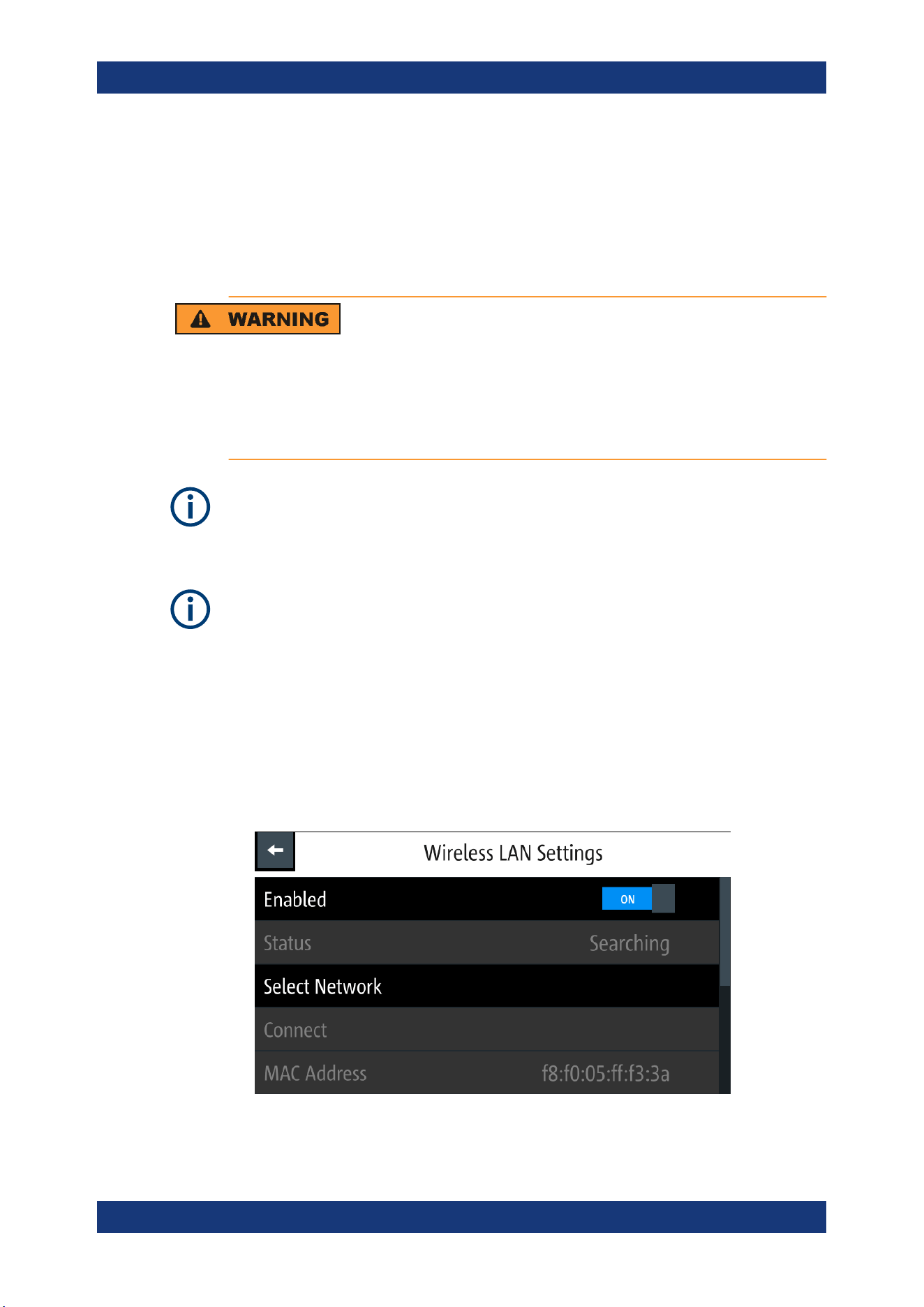
Instrument Functions
R&S
®
NGL200/NGM200
87User Manual 1178.8736.02 ─ 09
7. Select "Set" to confirm the value.
8. Select "Apply Configuration" to apply the changes.
6.16.1.2 Wireless LAN Connection
Risk of RF exposure
When WLAN is active, a minimum separation distance of 20 cm from front panel of the
instrument must be observed at all times.
When WLAN is active, no operation of antenna or transmitter should be co-located with
the instrument.
Wi-Fi transmitter performance
Frequency range: 2412 MHz to 2472 MHz
Power: 19.5 dBm typical
Instrument option
R&S NGL-K102 (P/N: 3652.6362.02) or R&S NGM-K102 (P/N: 3644.6367.02) option is
required to connect the R&S NGL/NGM to a network via wireless LAN connection.
An alterative to connection in local area network is wireless LAN connection. With the
presence of an authenticated Wi-Fi signal, the R&S NGL/NGM automatically connects
to a network and navigation can be made via the web browser according to the WLAN
IEEE 802.11 b/g/n standards.
1. Select "Wireless LAN" to set LAN connection.
The R&S NGL/NGM displays the "Wireless LAN Settings" dialog.
Figure 6-40: WLAN settings dialog
Interfaces
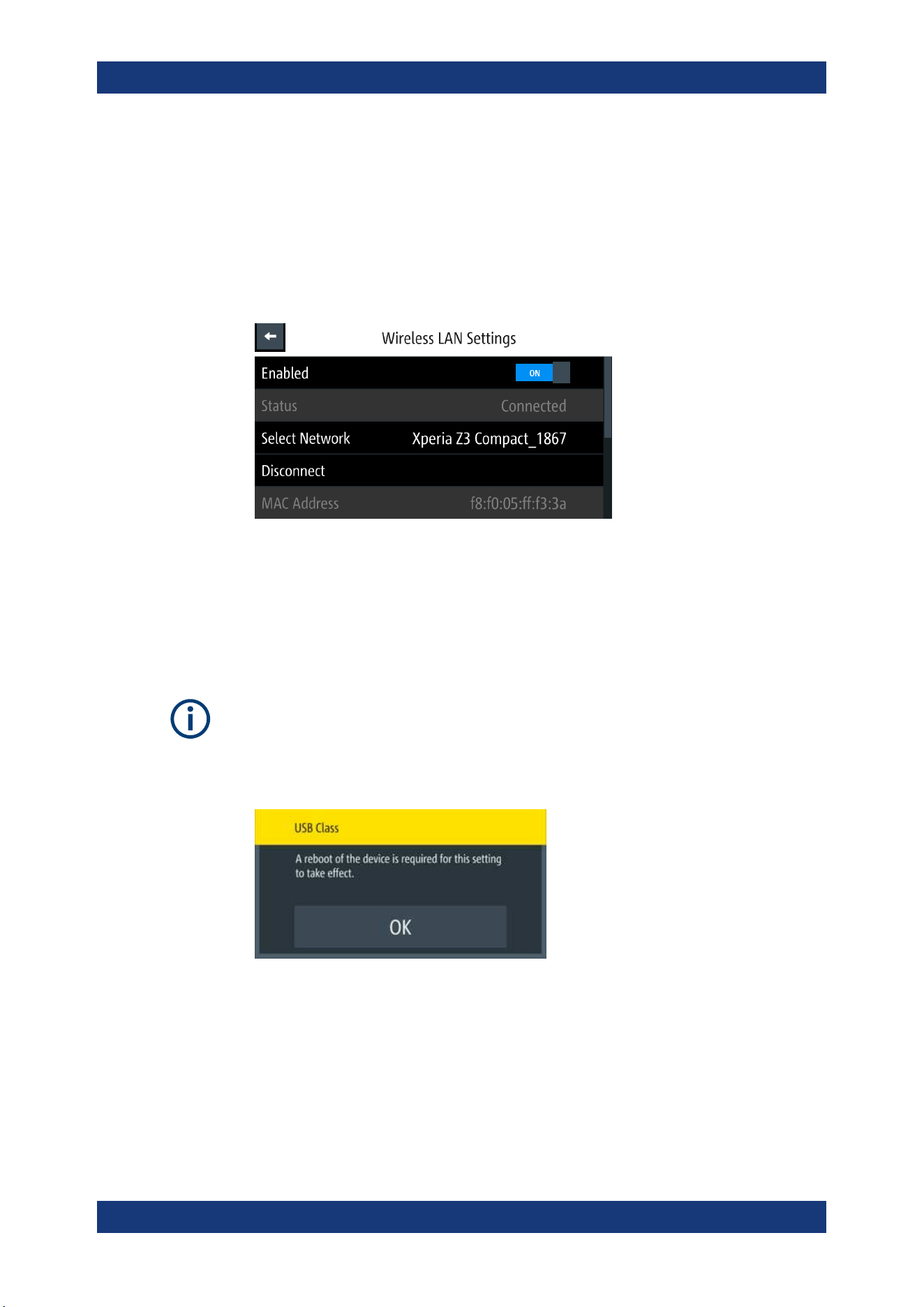
Instrument Functions
R&S
®
NGL200/NGM200
88User Manual 1178.8736.02 ─ 09
2. Select "Enable" menu item to set "On" to enable wireless LAN.
The R&S NGL/NGM began searching available WiFi network and the "Status"
shows "Searching".
3. Select the "Select Network" to connect the required WiFi network.
If connection is successful, the "Status" shows "Connected". See
Figure 6-41.
When the connection is alive, the WLAN icon turns white on the device status bar.
See "Device status bar" on page 30.
Figure 6-41: WLAN connected
4. To disconnect, select the Disconnect in the "Wireless LAN settings" dialog.
6.16.2 USB Connection
Change of USB class
If a change in "USB Class" is detected (i.e. from "TMC" to "CDC" or vice versa), the
rebooting of instrument is necessary to load the correct USB driver.
●
A popup message is displayed: "A reboot of the device is required for this setting to
take effect.".
Alternatively, connect a USB cable to the USB port (see Figure 4-2) and PC for a USB
connection. The R&S NGL/NGM supports USB CDC and USB TMC connection.
1. Select "USB Class" from the "Network Connections" dialog.
The R&S NGL/NGM displays the USB class dialog to select the USB connection.
Interfaces
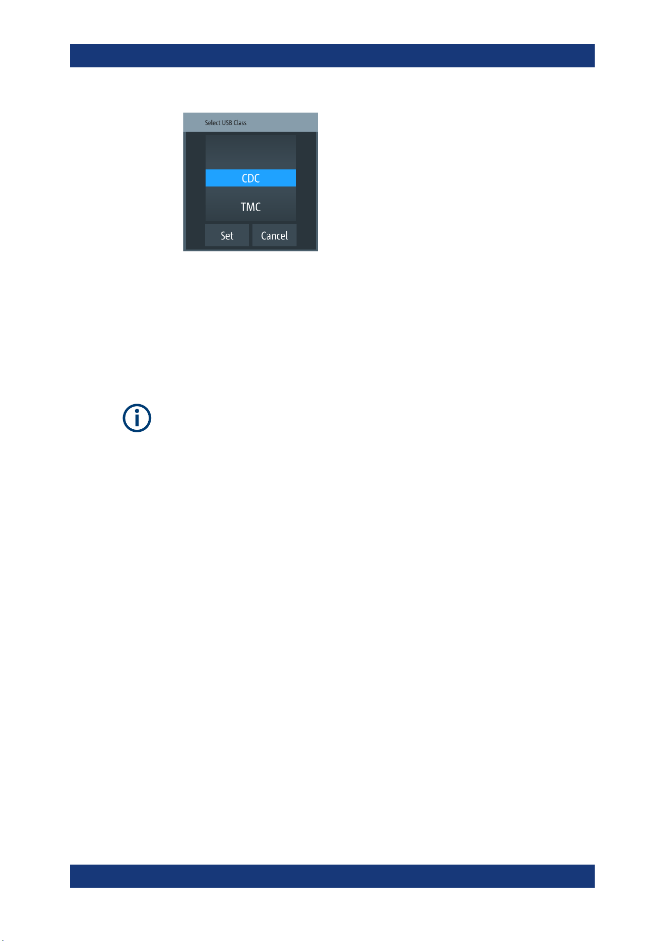
Instrument Functions
R&S
®
NGL200/NGM200
89User Manual 1178.8736.02 ─ 09
Figure 6-42: USB dialog
2. Set the USB class.
3. Select "Set" to confirm the selection.
6.16.3 GPIB Address
Instrument option
R&S NGL-B105 (P/N: 3652.6356.02) or R&S NGM-B105 (P/N: 3641.6220.02) option
needs to be installed for the remote command of R&S NGL/NGM via GPIB interface.
The GPIB interface, sometimes called the General Purpose Interface Bus (GPIB), is a
general purpose digital interface system that can be used to transfer data between two
or more devices. Some of its key features are:
●
Up to 15 instruments can be connected
●
The total cable length is restricted to a maximum of 15 m; the cable length between
two instruments should not exceed 2m
●
A wired "OR"-connection is used if several instruments are connected in parallel
To be able to control the instrument via the GPIB bus, the instrument and the controller
must be linked by a GPIB bus cable. A GPIB bus card, the card drivers and the pro-
gram libraries for the programming language must be provided in the controller. The
controller must address the instrument with the GPIB instrument address.
GPIB instrument address
To operate the instrument via remote control, it must be addressed using the GPIB
address. The default remote control address is factory-set at 20, the addresses of 0
through 30 are allowed.
The GPIB address is maintained after a reset of the instrument settings.
1. Select "GPIB Address" from the
Figure 6-36.
The R&S NGL/NGM displays an on-screen keypad to set the value.
Interfaces
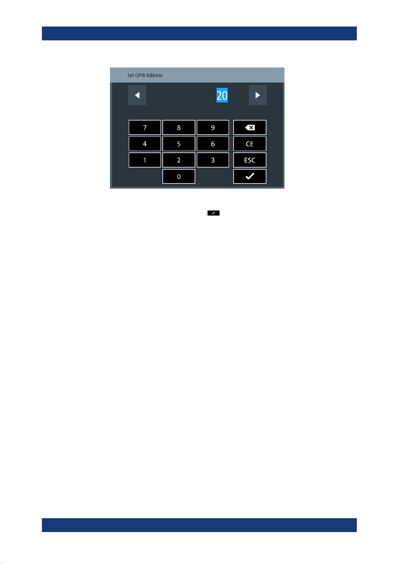
Instrument Functions
R&S
®
NGL200/NGM200
90User Manual 1178.8736.02 ─ 09
2. Enter the required value.
3.
Confirm value with the enter key
.
6.17 General Instrument Settings
The following chapters provide the general instrument information and utilities services
in "Device" menu.
1. Press [Settings] key.
The R&S NGL/NGM displays the device/channel menu window.
2. Select the "Device" tab.
The R&S NGL/NGM displays the device menu.
6.17.1 Licenses Management
Options are enabled by entering a registered license key code.
You may choose to install from an XML file on USB or by manually entering the key
code.
► Select "Licenses" to install license key code.
The R&S NGL/NGM displays the license dialog.
● "Active": Options that are currently active in the instrument
● "Inactive": Options that are currently not active in the instrument
● "Deactivation": Options that are expried or removed in the instrument
General Instrument Settings
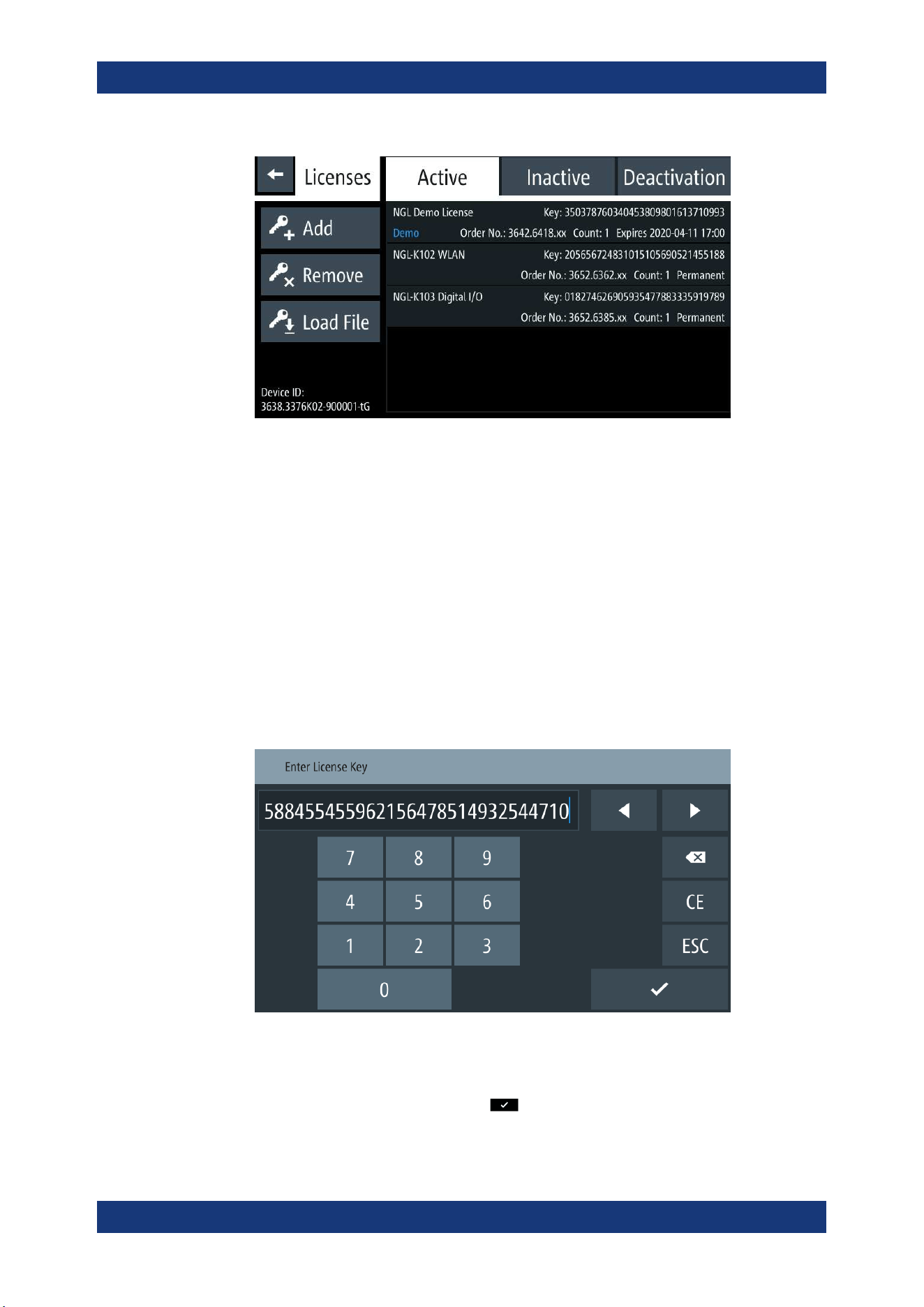
Instrument Functions
R&S
®
NGL200/NGM200
91User Manual 1178.8736.02 ─ 09
Figure 6-43: License dialog
To install an XML file, proceed as follows:
1. Copy the XML file containing the registered key code into the USB flash drive.
2. Connect the USB flash drive to the USB port of the instrument.
3. Select "Load File" to load the license file from the USB stick.
4. Select the license file to install in the instrument.
The R&S NGL/NGM install the license option accordingly.
If the installation is successful, the option is displayed in the "Active" window.
To manually enter the key code, proceed as follows:
1. Select "Add" key to invoke the license key on-screen keyboard.
Figure 6-44: License key on-screen keyboard
2. Enter the key code (30-digit number) of the option in the entry box.
3.
Confirm entries with the enter key
.
General Instrument Settings
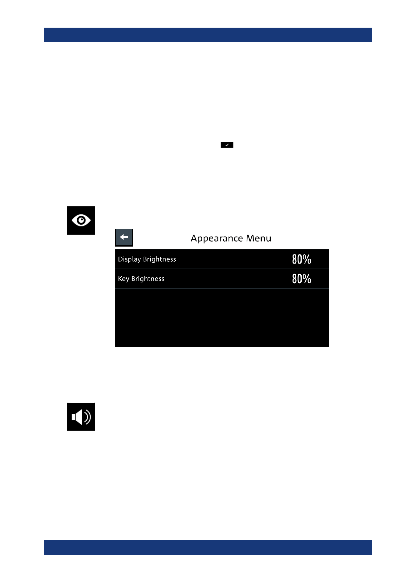
Instrument Functions
R&S
®
NGL200/NGM200
92User Manual 1178.8736.02 ─ 09
If the correct key code is entered, the R&S NGL/NGM popup a message "Device-
key is installed" and the option is displayed in the "Active" window.
4. To remove the option, select "Remove" from the license dialog.
The R&S NGL/NGM displays the license key on-screen keyboard. See
Fig-
ure 6-44
.
5. Enter the key code (30-digit number) of the option in the entry box.
6.
Confirm entries with the enter key
.
If the correct key code is entered, the R&S NGL/NGM popup a message "Device-
key is removed" and the option is displayed in the "Deactivation" window.
6.17.2 Appearance Settings
► Select the "Appearance" to set display and key brightness.
The R&S NGL/NGM displays the appearance dialog.
Figure 6-45: Appearance dialog
6.17.3 Sound Settings
1. Select the "Sound Settings" to set sound settings.
The R&S NGL/NGM displays the sound settings dialog.
General Instrument Settings
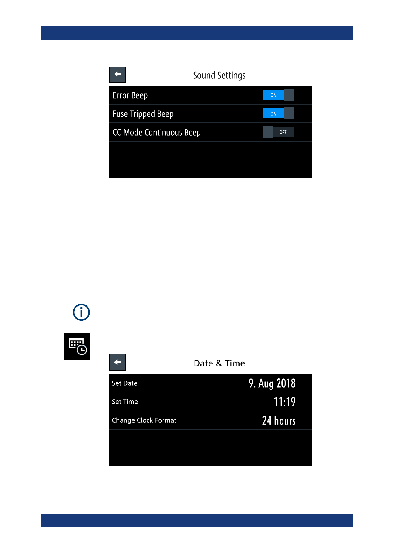
Instrument Functions
R&S
®
NGL200/NGM200
93User Manual 1178.8736.02 ─ 09
Figure 6-46: Sound settings dialog
2. Select the required fields to set alert.
● "Error Beep": A single beep alert when error occurs.
● "Fuse Tripped Beep": A single beep alert when a fuse tripped occurs. See
Chapter 6.5, "Protection", on page 58.
● "CC-Mode Continuous Beep": A continuous beep sound alert when the
selected output channel goes into CC mode. See "CC mode" on page 42.
6.17.4 Date and Time
The time is regarded as UTC. There is no timezone selectable.
1. Select the "Date & Time" to set date and time format.
The R&S NGL/NGM displays the date and time dialog.
Figure 6-47: Date and time setting dialog
General Instrument Settings
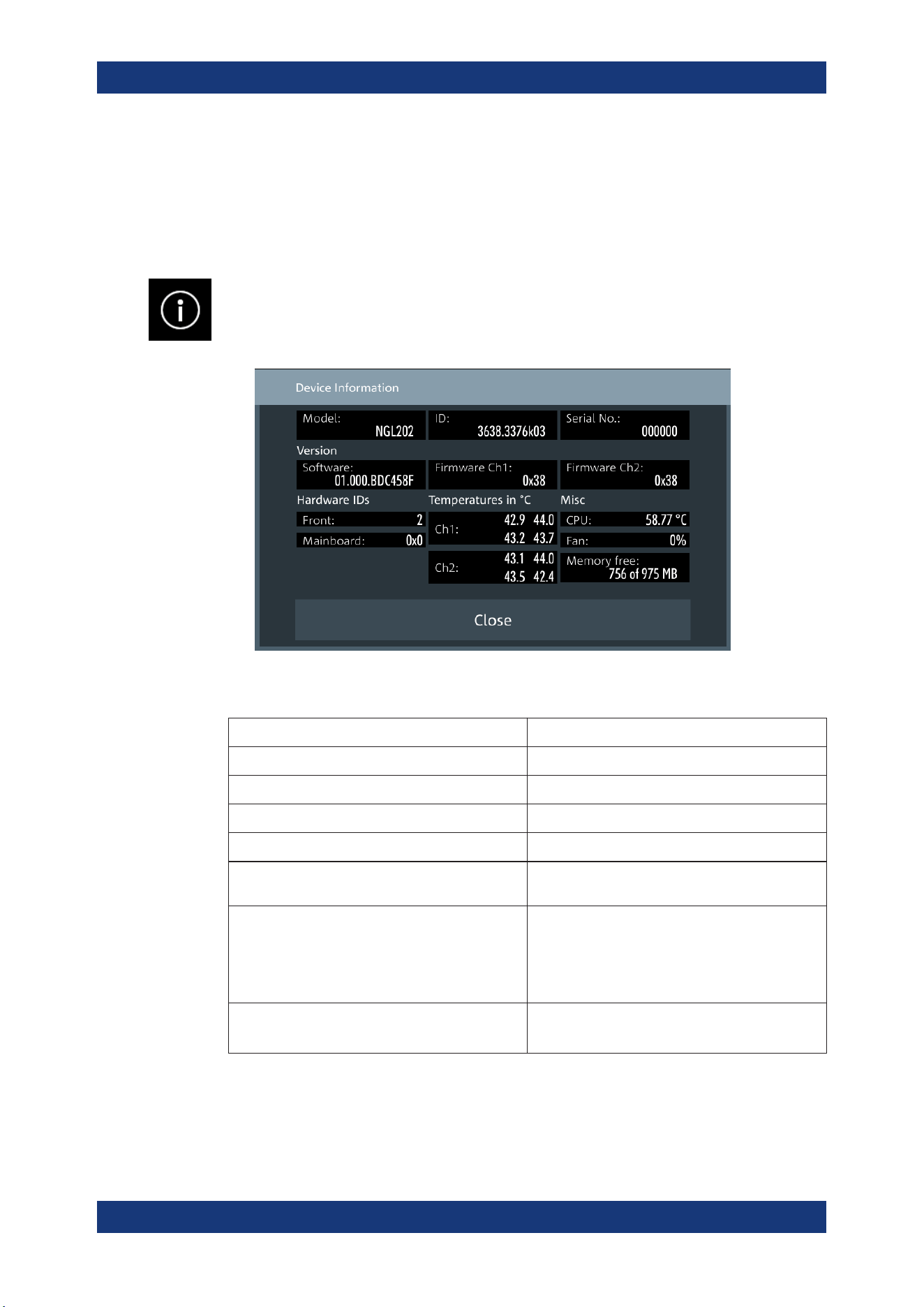
Instrument Functions
R&S
®
NGL200/NGM200
94User Manual 1178.8736.02 ─ 09
2. Select the required field to configure.
The R&S NGL/NGM reset the instrument date and time accordingly.
6.17.5 Device Information
General instrument information of R&S NGL/NGM.
► Select the "Instrument Information" to display the device information.
The R&S NGL/NGM displays the device information dialog.
Figure 6-48: Device information dialog
Device information Description
Model Model of the instrument.
ID Instrument orderable part number.
Serial No. Unique identification number for the instrument.
Version Software version that is installed in the instrument.
Hardware IDs Unique serial number of the front and mainboard of
the instrument.
Temperatures Temperature in degrees measured in both Ch1 and
Ch2.
If the temperature exceeded the specification, "Over
Temperature Protection" (OTP) is triggered and the
respective output channel is turned off.
Misc Temperature measures for CPU.
Fan speed and memory capacity in the instrument.
6.17.6 Update Device
General Instrument Settings
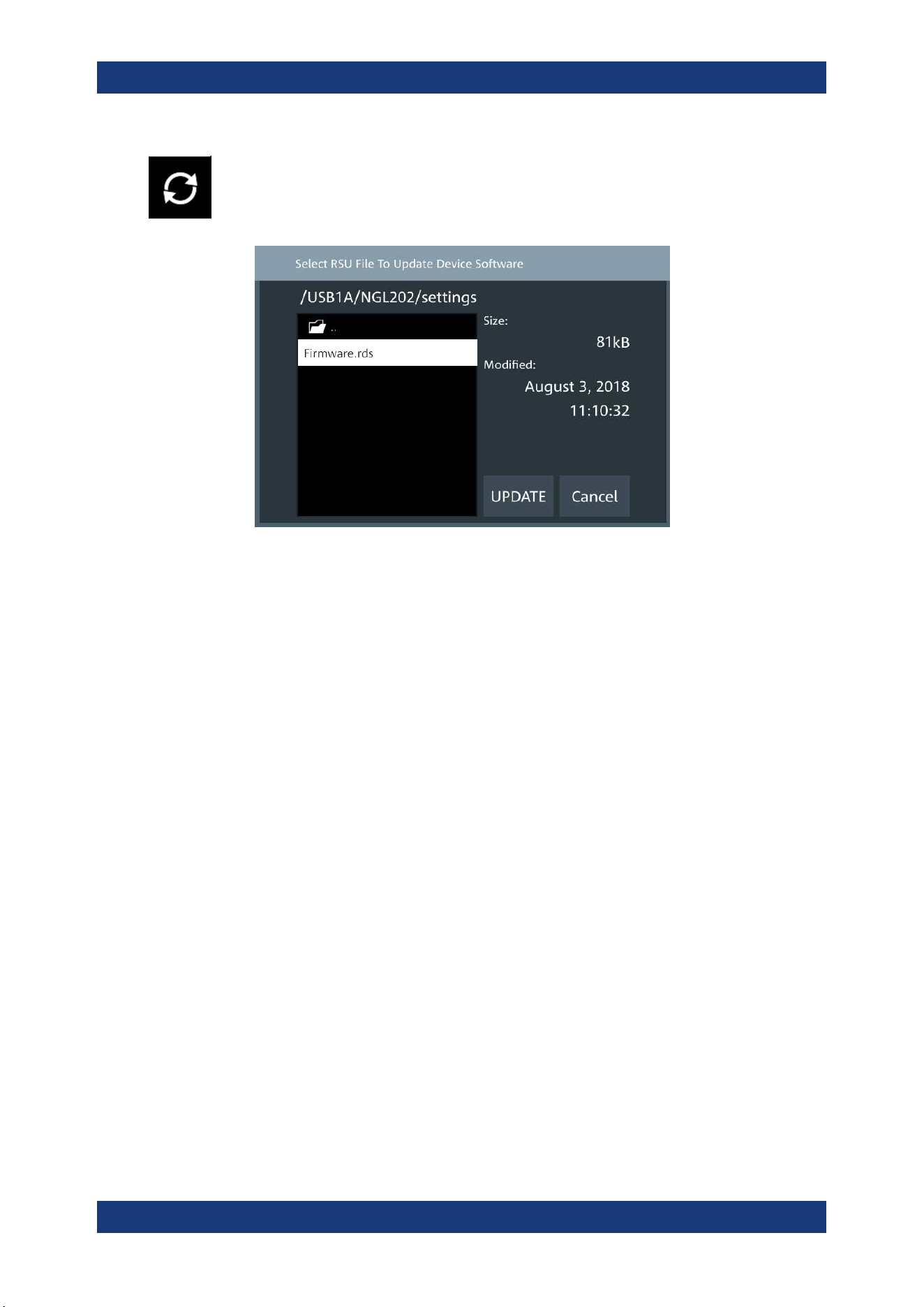
Instrument Functions
R&S
®
NGL200/NGM200
95User Manual 1178.8736.02 ─ 09
Latest instrument firmware is available in the R&S NGL/NGM product homepage.
1. Select the "Update Device" to update instrument firmware.
The R&S NGL/NGM displays the update device dialog.
Figure 6-49: Update device dialog
2. Select the source and file location to update instrument firmware.
3. Select "UPDATE" to update the instrument firmware.
The R&S NGL/NGM updates the instrument firmware accordingly.
6.18 Device Documentation
You can retrieve the R&S NGL/NGM Open Source Acknowledgment documentation
from the instrument documentation folder /int/documentation.
1. Go to "File Manager" menu.
The R&S NGL/NGM displays the file manager dialog.
For more information, see
Chapter 6.14, "File Manager", on page 80.
2. Select the documentation folder in the file manager dialog.
The R&S NGL/NGM displays the available files in the documentation folder.
3. Select the file you want to copy from the documentation folder.
Device Documentation

Remote Control Commands
R&S
®
NGL200/NGM200
96User Manual 1178.8736.02 ─ 09
7 Remote Control Commands
This chapter provides the description of all remote commands available for the
R&S NGL/NGM series. The commands are sorted according to the menu structure of
the instrument. A list of commands in alphabetical order is given in the "List of Com-
mand"s at the end of this documentation.
For more information on
Messages and Command Structure, Messages and Com-
mand Structure
and Structure of a SCPI Status Register, see the "Annex" at the end of
this documentation.
7.1 Common Setting Commands
Common commands are described in the IEEE 488.2 (IEC 625-2) standard. These
commands have the same effect and are employed in the same way on different devi-
ces. The headers of these commands consist of "*" followed by three letters.
Many common commands are related to the Status Reporting System.
*CLS...............................................................................................................................96
*ESE...............................................................................................................................96
*ESR?.............................................................................................................................97
*IDN?..............................................................................................................................97
*OPC..............................................................................................................................97
*OPT?.............................................................................................................................97
*RST...............................................................................................................................97
*SRE.............................................................................................................................. 98
*STB?.............................................................................................................................98
*TRG.............................................................................................................................. 98
*TST?............................................................................................................................. 98
*WAI...............................................................................................................................98
*CLS
Clear status
Sets the status byte (STB), the standard event register (ESR) and the EVENt part of
the QUEStionable and the OPERation registers to zero. The command does not
alter the mask and transition parts of the registers. It clears the output buffer.
Usage: Setting only
*ESE <Value>
Event status enable
Sets the event status enable register to the specified value. The query returns the con-
tents of the event status enable register in decimal form.
Common Setting Commands

Remote Control Commands
R&S
®
NGL200/NGM200
97User Manual 1178.8736.02 ─ 09
Parameters:
<Value> Range: 0 to 255
*ESR?
Event status read
Returns the contents of the event status register in decimal form and then sets the reg-
ister to zero.
Return values:
<Contents> Range: 0 to 255
Usage: Query only
*IDN?
Identification
Returns the instrument identification.
Return values:
<ID> "Rohde&Schwarz,<device type>,<part number>/<serial num-
ber>,<firmware version>"
Usage: Query only
*OPC
Operation complete
Sets bit 0 in the event status register when all preceding commands have been execu-
ted. This bit can be used to initiate a service request. The query writes a "1" into the
output buffer when all preceding commands have been executed, which is useful for
command synchronization.
*OPT?
Option identification query
Queries the options included in the instrument. For a list of all available options and
their description, refer to the data sheet.
Usage: Query only
*RST
Reset
Sets the instrument to a defined default status. The default settings are indicated in the
description of commands.
Usage: Setting only
Common Setting Commands

Remote Control Commands
R&S
®
NGL200/NGM200
98User Manual 1178.8736.02 ─ 09
*SRE <Contents>
Service request enable
Sets the service request enable register to the indicated value. This command deter-
mines under which conditions a service request is triggered.
Parameters:
<Contents> Contents of the service request enable register in decimal form.
Bit 6 (MSS mask bit) is always 0.
Range: 0 to 255
*STB?
Status byte query
Reads the contents of the status byte in decimal form.
Usage: Query only
*TRG
Recall
Triggers all actions waiting for a trigger event. In particular, *TRG generates a manual
trigger signal. This common command complements the commands of the TRIGger
subsystem.
Usage: Event
*TST?
Self-test query
Initiates self-tests of the instrument and returns an error code.
Return values:
<ErrorCode> integer > 0 (in decimal format)
An error occurred.
0
No errors occurred.
Usage: Query only
*WAI
Wait to continue
Prevents servicing of the subsequent commands until all preceding commands have
been executed and all signals have settled (see also command synchronization and
*OPC).
Usage: Event
Common Setting Commands

Remote Control Commands
R&S
®
NGL200/NGM200
99User Manual 1178.8736.02 ─ 09
7.2 System Settings Commands
The SYSTem subsystem contains the commands for general functions, which do not
affect signal generation directly.
SYSTem:BEEPer:CURRent:STATe.................................................................................... 99
SYSTem:BEEPer:PROTection:STATe.................................................................................99
SYSTem:BEEPer:PROTection[:IMMediate]......................................................................... 99
SYSTem:BEEPer:STATe................................................................................................. 100
SYSTem:LOCal..............................................................................................................100
SYSTem:REMote........................................................................................................... 100
SYSTem:RWLock...........................................................................................................100
SYSTem:KEY:BRIGhtness.............................................................................................. 100
SYSTem:DATE.............................................................................................................. 101
SYSTem:TIME............................................................................................................... 101
SYSTem:BEEPer:CURRent:STATe <arg0>
Enables or disables beep sound for "current control" alert.
Parameters:
<arg0> 1
Enables the "Current control" beep sound, a continuous beep
sound alert when the selected output channel goes into CC
mode.
0
Disables the "Current control" beep sound.
SYSTem:BEEPer:PROTection:STATe <arg0>
Enables or disables beep sound for "protection" alert.
Parameters:
<arg0> 1
Enables the "protection" beep sound, a single beep alert when a
fuse tripped occurs.
0
Disables the "protection" beep sound.
SYSTem:BEEPer:PROTection[:IMMediate]
Return a single "protection" beep sound immediately.
Usage: Event
System Settings Commands

Remote Control Commands
R&S
®
NGL200/NGM200
100User Manual 1178.8736.02 ─ 09
SYSTem:BEEPer:STATe <Mode>
SYSTem:BEEPer:STATe?
Sets or queries the beeper tone.
Parameters:
<Mode> 1
Control beeper is activated.
0
Control beeper is deactivated.
Example:
SYSTem:BEEPer:STATe 1
The front panel control beeper is activated.
Example:
SYSTem:BEEPer:STATe?
Queries the state of the front panel control beeper. Returns “0”
for deactivated (OFF) and “1” for activated (ON) control beeper.
SYSTem:LOCal
Sets the system to front panel control. The front panel control is unlocked. If the front
panel control was locked with the SCPI command SYSTem:RWLock, the message box
of the locked front panel on the instrument display will be disappeared.
Usage: Setting only
SYSTem:REMote
Sets the system to remote state. The front panel control is locked. By pushing the soft-
key button [*] key, the front panel control will be activated.
Usage: Setting only
SYSTem:RWLock
Sets the system to remote state. The front panel control is locked and a message box
is shown on the instrument display. You are only able to unlock the front panel control
via SCPI command SYSTem:LOCal.
Usage: Setting only
SYSTem:KEY:BRIGhtness <brightness>
SYSTem:KEY:BRIGhtness?
Sets or queries the front panel key brightness.
Parameters:
<brightness> Sets the key brightness.
Range: 0.0 to 1.0
Increment: 0.1
*RST: 1.0
System Settings Commands

Remote Control Commands
R&S
®
NGL200/NGM200
101User Manual 1178.8736.02 ─ 09
Example:
SYSTem:KEY:BRIGhtness 1.0
SYSTem:KEY:BRIGhtness? -> 1.0
Returns key brightness value: 1.0.
SYSTem:DATE <year>, <month>, <day>
SYSTem:DATE?
Sets or queries the system date.
Parameters:
<year> Sets year of the date.
<month> Sets month of the date.
<day> Sets day of the date.
Example:
SYSTem:DATE 2018, 10, 15
SYSTem:DATE? -> 2018, 10, 15
Returns the system date.
SYSTem:TIME <hh>, <mm>, <ss>
SYSTem:TIME?
Sets or queries the system time.
Parameters:
<hh> Sets the hours of the system time.
<mm> Sets the minutes of the system time.
<ss> Sets the seconds of the system time.
Example:
SYSTem:TIME 12, 30, 59
SYSTem:TIME? -> 12, 30, 59
Returns system time.
7.3 Display Commands
The DISPlay subsystem contains the commands for display functions, which do not
affect signal generation directly.
DISPlay:BRIGhtness...................................................................................................... 101
DISPlay[:WINDow]:TEXT:CLEar...................................................................................... 102
DISPlay[:WINDow]:TEXT[:DATA]..................................................................................... 102
DISPlay:BRIGhtness <brightness>
DISPlay:BRIGhtness?
Sets or queries the display brightness.
Display Commands

Remote Control Commands
R&S
®
NGL200/NGM200
102User Manual 1178.8736.02 ─ 09
Parameters:
<brightness> Displays brightness for the instrument.
Range: 0.0 to 1.0
Increment: 0.1
*RST: 0.8
Example:
DISPlay:BRIGhtness 0.5
DISPlay:BRIGhtness? -> 0.5
Returns the display brightness value.
DISPlay[:WINDow]:TEXT:CLEar
Clears the text message box on the front display.
Usage: Setting only
DISPlay[:WINDow]:TEXT[:DATA] <string>
Displays a text message box on the front display.
Setting parameters:
<string> Text message for display.
Example:
DISPlay:TEXT "Instrument Test"
Usage: Setting only
7.4 Trigger Commands
The TRIGger subsystem contains the commands for signal triggering.
TRIGger[:STATe]............................................................................................................102
TRIGger[:SEQuence][:IMMediate]:SOURce......................................................................103
TRIGger[:SEQuence][:IMMediate]:SOURce:DIO:CHANnel.................................................103
TRIGger[:SEQuence][:IMMediate]:SOURce:DIO:PIN......................................................... 104
TRIGger[:SEQuence][:IMMediate]:SOURce:OMODe......................................................... 104
TRIGger[:SEQuence][:IMMediate]:SOURce:OMODe:CHANnel...........................................105
TRIGger[:SEQuence][:IMMediate]:SOURce:OUTPut:CHANnel........................................... 105
TRIGger[:STATe] <arg0>
Enables or disables the trigger system.
Upon being triggered, the selected trigger source
TRIGger[:SEQuence][:
IMMediate]:SOURce
on page 103 becomes active.
See
Figure 6-18.
Setting parameters:
<arg0> 1
Enables the trigger system.
Trigger Commands

Remote Control Commands
R&S
®
NGL200/NGM200
103User Manual 1178.8736.02 ─ 09
0
Disables the trigger system.
TRIGger[:SEQuence][:IMMediate]:SOURce <arg0>
TRIGger[:SEQuence][:IMMediate]:SOURce? <arg0>
Sets or queries the trigger source.
See
Figure 6-18.
Parameters for setting and query:
<arg0> OUTPut | OMODe | DIO
OUTPut
Trigger source is from the output channel (Ch1, Ch2).
OMODe
Trigger source is from the different modes (CC, CR, CV, Sink,
OVP, OCP, OPP and OTP) detected from the output channel
(Ch1, Ch2).
DIO
Trigger source is from DIO connector at the instrument rear
panel.
Example:
TRIG:SOUR OMOD
Trigger source "Operation Modes" is selected for monitoring.
TRIGger[:SEQuence][:IMMediate]:SOURce:DIO:CHANnel <arg0>
TRIGger[:SEQuence][:IMMediate]:SOURce:DIO:CHANnel? <arg0>
Sets or queries the device channel for trigger source "Digital In Channel".
See
Figure 6-18.
Note: This setting is only available if DIO pin is set to "EXT". See
TRIGger[:
SEQuence][:IMMediate]:SOURce:DIO:PIN
on page 104.
Parameters for setting and query:
<arg0> OUT1 | OUTP1 | OUTPut1 | OUT2 | OUTP2 | OUTPut2 | ANY
OUT1 | OUTP1 | OUTPut1
Ch1 is selected as the device channel for trigger source.
OUT2 | OUTP2 | OUTPut2
Ch2 is selected as the device channel for trigger source.
ANY
Any of the available channel which meets the condition sets as
the trigger source.
Example:
TRIG:SOUR:DIO:CHAN 1
Ch1 is selected as the device channel for trigger source "Digital
In Channel".
Trigger Commands

Remote Control Commands
R&S
®
NGL200/NGM200
104User Manual 1178.8736.02 ─ 09
TRIGger[:SEQuence][:IMMediate]:SOURce:DIO:PIN <arg0>
TRIGger[:SEQuence][:IMMediate]:SOURce:DIO:PIN? <arg0>
Sets or queries the DIO pin to trigger on for trigger source "Digital In Channel".
See
Figure 6-18.
Parameters for setting and query:
<arg0> IN | EXT
IN
Pin 3 of DIO connector is monitored.
EXT
Pin 2 (Ch1) and Pin 10 (Ch2) of DIO connector is monitored.
Example:
TRIG:SOUR:DIO:PIN IN
Pin 3 of DIO connector is monitored for trigger source "Digital In
Channel".
TRIGger[:SEQuence][:IMMediate]:SOURce:OMODe <arg0>
TRIGger[:SEQuence][:IMMediate]:SOURce:OMODe? <arg0>
Sets or queries the operation mode to trigger on for trigger source "operation mode"
See
Figure 6-18.
Parameters for setting and query:
<arg0> CC | CV | CR | SINK | PROTection
CC
If respective channel operation mode is detected in CC mode,
corresponding trigger-out parameters are triggered.
CV
If respective channel operation mode is detected in CV mode,
corresponding trigger-out parameters are triggered.
CR
If respective channel operation mode is detected in CR mode,
corresponding trigger-out parameters are triggered.
SINK
If respective channel operation mode is detected in sink mode,
corresponding trigger-out parameters are triggered.
PROTection
If respective channel operation mode is detected in protection
mode (OVP, OCP, OPP OTP), corresponding trigger-out param-
eters are triggered.
Example:
TRIG:SOUR OMOD
TRIG:SOUR:OMOD:CHAN OUT1
TRIG:SOUR:OMOD CV
If CV mode is detected on Ch1, a trigger event is activated to
corresponding trigger-out parameters.
Trigger Commands

Remote Control Commands
R&S
®
NGL200/NGM200
105User Manual 1178.8736.02 ─ 09
TRIGger[:SEQuence][:IMMediate]:SOURce:OMODe:CHANnel <arg0>
TRIGger[:SEQuence][:IMMediate]:SOURce:OMODe:CHANnel? <arg0>
Sets or queries the device channel for trigger source "Operation Modes".
See
Figure 6-18.
Parameters for setting and query:
<arg0> OUT1 | OUTP1 | OUTPut1 | OUT2 | OUTP2 | OUTPut2 | ANY
OUT1 | OUTP1 | OUTPut1
Ch1 is selected as the device channel for trigger source.
OUT2 | OUTP2 | OUTPut2
Ch2 is selected as the device channel for trigger source.
ANY
Any of the available channel which meets the condition sets as
the trigger source.
Example:
TRIG:SOUR:OMOD:CHAN 1
Ch1 is selected as the device channel for trigger source "Opera-
tion Modes".
TRIGger[:SEQuence][:IMMediate]:SOURce:OUTPut:CHANnel <arg0>
TRIGger[:SEQuence][:IMMediate]:SOURce:OUTPut:CHANnel? <arg0>
Sets or queries the device channel for trigger source "Output".
See Figure 6-18.
Parameters for setting and query:
<arg0> OUT1 | OUTP1 | OUTPut1 | OUT2 | OUTP2 | OUTPut2 | ANY
OUT1 | OUTP1 | OUTPut1
Ch1 is selected as the device channel for trigger source.
OUT2 | OUTP2 | OUTPut2
Ch2 is selected as the device channel for trigger source.
ANY
Any of the available channel which meets the condition sets as
the trigger source.
Example:
TRIG:SOUR:OUTP:CHAN 1
Ch1 is selected as the device channel for trigger source "Out-
put".
7.5 Configuration Commands
The following subsystems contain the commands for channel selection, voltage and
current settings for the instrument.
Configuration Commands

Remote Control Commands
R&S
®
NGL200/NGM200
106User Manual 1178.8736.02 ─ 09
7.5.1 Channel Selection
The INSTrument:Select subsystem contains the commands for selecting the output
channels.
Each channel of the power supply is considered as separate "instrument", which is
required by the SCPI standard. Therefore, the SCPI commands use the INSTRument
node to select a channel.
You can only address the number of channels the instrument is equipped with, e.g. a
maximum of two channels for the NGL202, NGM202 or one channel for the NGL201,
NGM201.
You can address the channel by using the channel list command synax.
For more information, see
"Syntax for Channel List Commands" on page 183.
Example: Selecting a channel
You can select a channel either with an OUTput parameter, or just by the channel
number. This example lists all ways how you can select and query a selected channel.
// ************************************************
// Select a channel
// ************************************************
// selects channel 1
INST OUT1
// queries the channel selection
INST?
// response: "OUT1"
// ************************************************
// Select a channel by its number
// ************************************************
// selects channel number 1
INST:NSEL 1
// queries number of the channel selection
INST:NSEL?
// response: 1
INSTrument:NSELect..................................................................................................... 106
INSTrument[:SELect]......................................................................................................107
INSTrument:NSELect <channel>
INSTrument:NSELect?
Selects or queries the channel by number.
Setting parameters:
<channel> 1 | 2
Range: 1 to 2
Example: See
Example "Selecting a channel" on page 106.
Configuration Commands

Remote Control Commands
R&S
®
NGL200/NGM200
107User Manual 1178.8736.02 ─ 09
INSTrument[:SELect] <channel>
INSTrument[:SELect]?
Selects or queries the channel by keyword.
Setting parameters:
<channel> OUT1 | OUTP1 | OUTPut1 | 1 | OUT2 | OUTP2 | OUTPut2 | 2
OUT1 | OUTP1 | OUTPut1 | 1
Selects Channel 1 (Ch1)
OUT2 | OUTP2 | OUTPut2 | 2
Selects Channel 2 (Ch2)
Range: 1 to 2
Example: See
Example "Selecting a channel" on page 106.
7.5.2 Safety Limit Setting
The SOURce:ALIM subsystem contains the commands for setting the safety limits of
the output channels.
Configuration Commands

Remote Control Commands
R&S
®
NGL200/NGM200
108User Manual 1178.8736.02 ─ 09
Example: Configuring the output voltage
This example contains all commands to configure and query the output voltage.
// ************************************************
// Select the channel
// ************************************************
INST OUT1
// ************************************************
// Set upper or lower voltage safety limit
// ************************************************
//sets the safety limits to enable
ALIM 1
//queries the safety limits state
ALIM?
//response: "1"
//sets the safety limits for the upper voltage
VOLT:ALIM 15
//queries the safety limits for the upper voltage
VOLT:ALIM?
//reponse: "15.000"
//sets the safety limits for the lower voltage
VOLT:ALIM:LOW 0
//queries the safety limits for the lower voltage
VOLT:ALIM:LOW?
//reponse: "0.000"
//sets the safety limits for the upper current
CURR:ALIM 3
//queries the safety limits for the upper current
CURR:ALIM?
//reponse: "3.000"
//sets the safety limits for the lower current
CURR:ALIM:LOW 0
//queries the safety limits for the lower current
CURR:ALIM:LOW?
//reponse: "0.000"
[SOURce:]ALIMit[:STATe]................................................................................................108
[SOURce:]VOLTage[:LEVel][:IMMediate]:ALIMit:LOWer..................................................... 109
[SOURce:]VOLTage[:LEVel][:IMMediate]:ALIMit[:UPPer].................................................... 109
[SOURce:]CURRent[:LEVel][:IMMediate]:ALIMit:LOWer..................................................... 110
[SOURce:]CURRent[:LEVel][:IMMediate]:ALIMit[:UPPer]....................................................110
[SOURce:]ALIMit[:STATe] <state>
[SOURce:]ALIMit[:STATe]? [<Channel list>]
Sets or queries the safety limit state.
Parameters:
<state> 1
Activates the safety limit.
Configuration Commands

Remote Control Commands
R&S
®
NGL200/NGM200
109User Manual 1178.8736.02 ─ 09
0
Deactivates the safety limit.
Parameters for setting and query:
<Channel list> <list>
Example:
ALIM 1, (@1)
Activates the safety limit state at channel 1
Example: See
Example "Configuring the output voltage" on page 112.
[SOURce:]VOLTage[:LEVel][:IMMediate]:ALIMit:LOWer <voltage>
[SOURce:]VOLTage[:LEVel][:IMMediate]:ALIMit:LOWer? [<Channel list>]
Sets or queries the lower safety limit for voltage.
Setting parameters:
<voltage> <numeric value> | MIN | MINimum | MAX | MAXimum | <list>
<numeric vaule>
Numeric value for safety limit.
MIN | MINimum
Min value for lower safety limit.
MAX | MAXimum
Max value for lower safety limit.
Range: 0.000E+00 to 2.050E+01
Increment: 0.001
*RST: 0.000E+00
Parameters for setting and query:
<Channel list> <list>
Example:
VOLT:ALIM:LOW? (@1)
Queries the lower safety limit for volatage at channel 1
Example: See
Example "Configuring the output voltage" on page 112.
[SOURce:]VOLTage[:LEVel][:IMMediate]:ALIMit[:UPPer] <voltage>
[SOURce:]VOLTage[:LEVel][:IMMediate]:ALIMit[:UPPer]? [<Channel list>]
Sets or queries the upper safety limit for voltage.
Setting parameters:
<voltage> <numeric value> | MIN | MINimum | MAX | MAXimum | <list>
<numeric value>
Numeric value for upper safety limit.
MIN | MINimum
Min value for upper safety limit.
MAX | MAXimum
Max value for upper safety limit.
Range: 0.000E+00 to 2.050E+01
Increment: 0.001
Configuration Commands

Remote Control Commands
R&S
®
NGL200/NGM200
110User Manual 1178.8736.02 ─ 09
*RST: 2.050E+01
Parameters for setting and query:
<Channel list> <list>
Example:
VOLT:ALIM:UPP? (@1)
Queries the upper safety limit for voltage at channel 1.
Example: See
Example "Configuring the output voltage" on page 112.
[SOURce:]CURRent[:LEVel][:IMMediate]:ALIMit:LOWer <current>
[SOURce:]CURRent[:LEVel][:IMMediate]:ALIMit:LOWer? [<Channel list>]
Sets or queries the lower safety limit for current.
Setting parameters:
<current> <numeric value> | MIN | MINimum | MAX | MAXimum | <list>
<numeric value>
Numeric value for lower safety limit.
MIN | MINimum
Min value for lower safety limit.
MAX | MAXimum
Max value for lower safety limit.
Range: For up to 6V: 0.001E+00 to 3.010E+00. For above
6V: 0.001E+00 to 6.010E+00
Increment: 0.001
*RST: 0.001E+00
Parameters for setting and query:
<Channel list> <list>
Example:
CURR:ALIM:LOW? (@1)
Queries the lower safety limit for current at channel 1.
Example: See
Example "Configuring the current output" on page 115.
[SOURce:]CURRent[:LEVel][:IMMediate]:ALIMit[:UPPer] <current>
[SOURce:]CURRent[:LEVel][:IMMediate]:ALIMit[:UPPer]? [<Channel list>]
Sets or queries the upper safety limit for current.
Setting parameters:
<current> <numeric value> | MIN | MINimum | MAX | MAXimum | <list>
<numeric value>
Numeric value for upper safety limit.
MIN | MINimum
Min value for upper safety limit.
MAX | MAXimum
Max value for upper safety limit.
Range: For up to 6V: 0.001E+00 to 3.010E+00. For above
6V: 0.001E+00 to 6.010E+00
Configuration Commands

Remote Control Commands
R&S
®
NGL200/NGM200
111User Manual 1178.8736.02 ─ 09
Increment: 0.001
*RST: 6.010E+00
Parameters for setting and query:
<Channel list> <list>
Example:
CURR:ALIM:UPP? (@1)
Queries the upper safety limit for current at channel 1.
Example: See
Example "Configuring the current output" on page 115.
7.5.3 Voltage Setting
The SOURce:VOLTage subsystem contains the commands for setting the voltage of
the output channels. The default unit is V.
Configuration Commands

Remote Control Commands
R&S
®
NGL200/NGM200
112User Manual 1178.8736.02 ─ 09
Example: Configuring the output voltage
This example contains all commands to configure and query the output voltage.
// ************************************************
// Select the channel
// ************************************************
INST OUT1
// ************************************************
// Set upper or lower voltage safety limit
// ************************************************
//sets the safety limits to enable
ALIM 1
//queries the safety limits state
ALIM?
//response: "1"
//sets the safety limits for the upper voltage
VOLT:ALIM 15
//queries the safety limits for the upper voltage
VOLT:ALIM?
//response: "15.000"
//sets the safety limits for the lower voltage
VOLT:ALIM:LOW 0
//queries the safety limits for the lower voltage
VOLT:ALIM:LOW?
//response: "0.000"
// ************************************************
// Set the voltage value
// ************************************************
// selects a channel and sets the voltage
VOLT 10
// sets the voltage to maximum or minimum respectively
VOLT MAX
VOLT MIN
// queries the output voltage of a channel
VOLT?
// response: "10.000"
// ************************************************
// Query the range of the voltage values
// ************************************************
// queries the upper and lower limit of the output voltage
VOLT? MIN
// response: "0.000"
VOLT? MAX
// response: "20.050"
// ************************************************
// Increase or decrease the voltage stepwise
// ************************************************
// selects the output channel, sets the step width
// and increases the voltage in the selected channel
// from 4 Volts
Configuration Commands

Remote Control Commands
R&S
®
NGL200/NGM200
113User Manual 1178.8736.02 ─ 09
INST OUT1
VOLT:STEP 4
VOLT UP
// decreases the voltage in the selected channel
// from 4 Volts
VOLT DOWN
// queries the voltage step size
VOLT:STEP?
// response: "4.000"
[SOURce:]VOLTage[:LEVel][:IMMediate][:AMPLitude]........................................................ 113
[SOURce:]VOLTage[:LEVel][:IMMediate]:STEP[:INCRement]..............................................114
[SOURce:]VOLTage[:LEVel][:IMMediate][:AMPLitude] <voltage>
[SOURce:]VOLTage[:LEVel][:IMMediate][:AMPLitude]? [<Channel list>]
Sets or queries the voltage value of the selected channel.
Parameters:
<voltage> <numeric value> | MIN | MINimum | MAX | MAXimum | UP |
DOWN | <list>
<numeric value>
Numeric value in V.
MIN | MINimum
Minimum voltage at 0.000 V.
MAX | MAXimum
Maximum voltage at 20.050 V.
UP
Increases voltage by a defined step size. See
[SOURce:
]VOLTage[:LEVel][:IMMediate]:STEP[:INCRement]
on page 114.
DOWN
Decreases voltage by a defined step size. See
[SOURce:
]VOLTage[:LEVel][:IMMediate]:STEP[:INCRement]
on page 114.
Range: 0.000 to 20.05
Default unit: V
Parameters for setting and query:
<Channel list> <list>
Example:
VOLT? (@1)
Queries the voltage at channel 1.
Example: See
Example "Configuring the output voltage" on page 112.
Configuration Commands

Remote Control Commands
R&S
®
NGL200/NGM200
114User Manual 1178.8736.02 ─ 09
[SOURce:]VOLTage[:LEVel][:IMMediate]:STEP[:INCRement] <stepsize>
[SOURce:]VOLTage[:LEVel][:IMMediate]:STEP[:INCRement]? [<Optional default
step query>]
Sets or queries the incremental step size for the
VOLT UP | VOLT DOWN command.
Setting parameters:
<stepsize> <numeric value> | DEF | DEFault
<numeric value>
Step value in V.
DEF | DEFault
Default value of stepsize.
Range: 0.001 to 5.000
Increment: 0.001
*RST: 0.100
Default unit: V
Parameters for setting and query:
<stepsize> DEF | DEFault
Queries the default voltage step size.
Example:
INST OUT1
VOLT:STEP 0.001
VOLT:STEP DEF
VOLT:STEP? DEF -> 0.10
Returns the default stepsize voltage.
See also
Example "Configuring the output voltage" on page 112.
7.5.4 Current Setting
The SOURce:CURRent subsystem contains the commands for setting the current limit
of the output channels. The default unit is A.
Configuration Commands

Remote Control Commands
R&S
®
NGL200/NGM200
115User Manual 1178.8736.02 ─ 09
Example: Configuring the current output
// ************************************************
// Select the channel
// ************************************************
INST OUT1
// ************************************************
// Set upper or lower current safety limit
// ************************************************
//sets the safety limits to enable
ALIM 1
//queries the safety limits state
ALIM?
//response: "1"
//sets the safety limits for the upper current
CURR:ALIM 3
//queries the safety limits for the upper current
CURR:ALIM?
//reponse: "3.000"
//sets the safety limits for the lower current
CURR:ALIM LOW 0.001
//queries the safety limits for the lower current
CURR:ALIM:LOW?
//response: "0.001"
// ************************************************
// Set the current value
// ************************************************
// selects a channel and sets the current
CURR 2
// queries the current of the selected channel
CURR?
// response: 2.000
// ************************************************
// Query the range of the current values
// ************************************************
// queries the upper and lower limit of the current
CURR? MIN
// response: 0.001
CURR? MAX
// response: 3.000
// ************************************************
// Increase or decrease the current stepwise
// ************************************************
// selects the output channel, sets the step width
// and decreases the current in the selected channel
// by the set 1 Ampere
INST OUT1
CURR:STEP 1
CURR DOWN
// increases the current in the selected channel
// by the set 1 Ampere
Configuration Commands

Remote Control Commands
R&S
®
NGL200/NGM200
116User Manual 1178.8736.02 ─ 09
CURR UP
// queries the current step size
CURR:STEP?
// response: 1.000
[SOURce:]CURRent[:LEVel][:IMMediate]:STEP[:INCRement]............................................. 116
[SOURce:]CURRent[:LEVel][:IMMediate][:AMPLitude]........................................................116
[SOURce:]CURRent[:LEVel][:IMMediate]:STEP[:INCRement] <stepsize>
[SOURce:]CURRent[:LEVel][:IMMediate]:STEP[:INCRement]? [<Optional default
step query>]
Sets or queries the incremental step size for the
CURR UP | CURR DOWN command.
Setting parameters:
<stepsize> <numeric value> | DEF | DEFault
<numeric value>
Step value in A.
DEF | DEFault
Default value of stepsize.
Range: 0.0001 to 2.000
Increment: 0.0001
*RST: 0.010
Default unit: A
Parameters for setting and query:
<Optional default step
query>
DEF | DEFault
Queries the default voltage step size.
Example:
INST OUT1
CURR:STEP 0.005
CURR:STEP DEF
VOLT:STEP? DEF -> 0.1000E+00
Returns the default stepsize for current.
See
Example "Configuring the current output" on page 115.
[SOURce:]CURRent[:LEVel][:IMMediate][:AMPLitude] <current>
[SOURce:]CURRent[:LEVel][:IMMediate][:AMPLitude]? [<Channel list>]
Sets or queries the current value of the selected channel.
Parameters:
<current> <numeric value> | MIN | MINimum | MAX | MAXimum | UP |
DOWN | <list>
<numeric value>
Numeric value in the range of 0.000 to 6.010.
MIN | MINimum
Minimum current at 0.010 A.
Configuration Commands

Remote Control Commands
R&S
®
NGL200/NGM200
117User Manual 1178.8736.02 ─ 09
MAX | MAXimum
Depending on the set voltage level, the maximum set current is
6.010 A.
For voltage range from 0 V to 6 V, maximum set current is 6.01
A.
For voltage > 6 V, maximum set current is 3.01 A.
UP
Increases current by a defined step size. See
[SOURce:
]CURRent[:LEVel][:IMMediate]:STEP[:INCRement]
on page 116.
DOWN
Decreases current by a defined step size. See
[SOURce:
]CURRent[:LEVel][:IMMediate]:STEP[:INCRement]
on page 116.
Parameters for setting and query:
<Channel list> <list>
Example:
CURR? (@1)
Queries the current at channel 1.
Example: See
Example "Configuring the current output" on page 115.
7.5.5 Resistance Setting
The SOURce:RESistance subsystem contains the commands for setting the resist-
ance limit of the output channels. The default unit is ohms.
Configuration Commands

Remote Control Commands
R&S
®
NGL200/NGM200
118User Manual 1178.8736.02 ─ 09
Example: Configuring the resistance limit
// ************************************************
// Select the channel
// ************************************************
INST OUT1
// ************************************************
// Set the resistance value
// ************************************************
// selects a channel and sets the resistance
RES 10
// queries the resistance of the selected channel
RES?
// response: 10.000
// ************************************************
// Query the range of the resistance values
// ************************************************
// queries the upper and lower limit of the resistance
RES? MIN
// response: 0.000
RES? MAX
// response: 10000
// ************************************************
// Aactivate the constant resistance mode
// ************************************************
// selects a channel and activate the constant resistance mode
RES:STAT 1
// queries the constant resistance mode
RES:STAT?
// response: 1
[SOURce:]RESistance[:LEVel][:IMMediate][:AMPLitude].....................................................118
[SOURce:]RESistance:STATe.......................................................................................... 119
[SOURce:]RESistance[:LEVel][:IMMediate][:AMPLitude] <resistance>
[SOURce:]RESistance[:LEVel][:IMMediate][:AMPLitude]? [<Channel list>]
Sets or queries the constant resistance target value.
Parameters:
<resistance> <numeric value> | MIN | MINimum | MAX | MAXimum | UP |
DOWN | <list>
<numeric value>
Numeric value in the range of 0.000 ohm to 10000 ohms.
MIN | MINimum
Minimum resistance at 0.000 ohm.
MAX | MAXimum
Maximum resistance at 10000 ohms.
UP
Increases resistance by a defined step size.
Configuration Commands

Remote Control Commands
R&S
®
NGL200/NGM200
119User Manual 1178.8736.02 ─ 09
DOWN
Decreases resistance by a defined step size.
Increment: 0.1 ohms
Default unit: ohms
Parameters for setting and query:
<Channel list> <list>
Example:
RES? (@1)
Queries the constant resistance target value at channel 1.
Example: See
Example "Configuring the resistance limit" on page 118.
[SOURce:]RESistance:STATe <state>
[SOURce:]RESistance:STATe? [<Channel list>]
Sets or queries the constant resistance mode.
Parameters:
<state> 0
Deactivates constant resistance mode.
1
Activates constant resistance mode.
Parameters for setting and query:
<Channel list> <list>
Example:
RES:STAT? (@1)
Queries the constant resistance mode at channel 1.
Example: See
Example "Configuring the resistance limit" on page 118
7.5.6 Combined Setting of Voltage and Current Setting
The APPLy subsystem provides a command that enables you to set the current and
voltage of a channel in one step.
The combined voltage and current setting command takes approximately 100 ms, i.e.
longer than the setting of a single value.
APPLy <voltage> [,<current>][,<output>]
Sets or queries the voltage and current value of the selected channel.
Parameters:
<voltage> <numeric value> | MIN | MINimum | MAX | MAXimum | DEF |
DEFault
<numeric value>
Numeric value for voltage in the range of 0.000 to 20.050.
MIN | MINimum
Min voltage at 0.000 V.
Configuration Commands

Remote Control Commands
R&S
®
NGL200/NGM200
120User Manual 1178.8736.02 ─ 09
MAX | MAXimum
Max value for voltage at 20.050V.
DEF | DEFault
Default voltage.
*RST: 1.000
Default unit: V
<current> <numeric value> | MIN | MINimum | MAX | MAXimum | DEFault
<numeric value>
Numeric value for current in the range of 0.000 to 6.010.
MIN | MINimum
Min current at 0.000 A.
MAX | MAXimum
Max value for current at 6.010 A.
DEF | DEFault
Numeric value for current.
*RST: 1.000
Default unit: A
<output> OUT1 | OUTP1 | OUTPut1 | OUT2 | OUTP2 | OUTPut2
OUT1 | OUTP1 | OUTPut1
Selects output for channel 1.
OUT2 | OUTP2 | OUTPut2
Selects output for channel 2.
Example:
INST OUT1
APPL 6,2
Sets 6 V and 2 A to output of channel 1.
APPL? -> 6.000, 2.000
Queries the voltage and current of the selected channel.
READ? [<Channel list>]
Queries the currently voltage-current measurement pair and returns them separated by
comma.
Parameters:
<Channel list> <list>
Example: READ? -> 1.001080E+00,1.004224E-02
Example:
READ? (@1)
Queries the voltage-current measurement pair at channel 1.
Usage: Query only
7.5.7 Output Setting
The OUTPut subsystem contains the commands for activating the output channels.
Configuration Commands

Remote Control Commands
R&S
®
NGL200/NGM200
121User Manual 1178.8736.02 ─ 09
Example: Activating the channels
You can activate a selected channel and turn on or off the outputs either individually or
all outputs simultaneously. This example lists all ways how you can activate and query
the outputs.
// ************************************************
// Activate a channel
// ************************************************
INST OUT1
// activates the selected channel
OUTP:SEL 1
// activates channel 1 and its output
OUTP 1
// queries the output state
OUTP?
// response: 1
// ************************************************
// Turn on all selected channels simultaneously
// ************************************************
// selects channels 1 and 2
// sets the voltage and current values for both channels
// activates both channels
INST:OUT1
VOLT 12
CURR 0.1
OUTP:SEL 1
INST:OUT2
VOLT 12
CURR 0.2
OUTP:SEL 1
// turns on the output of both channels
OUTP:GEN 1
OUTPut:GENeral[:STATe]............................................................................................... 122
OUTPut[:STATe].............................................................................................................122
OUTPut:DELay:DURation............................................................................................... 122
OUTPut:DELay[:STATe].................................................................................................. 123
OUTPut:FTResponse..................................................................................................... 123
OUTPut:IMPedance....................................................................................................... 124
OUTPut:IMPedance:STATe............................................................................................. 124
OUTPut:MODE..............................................................................................................125
OUTPut:SELect............................................................................................................. 125
OUTPut:TRIGgered........................................................................................................126
OUTPut:TRIGgered[:STATe]............................................................................................126
OUTPut:TRIGgered:BEHavior......................................................................................... 126
Configuration Commands

Remote Control Commands
R&S
®
NGL200/NGM200
122User Manual 1178.8736.02 ─ 09
OUTPut:GENeral[:STATe] <state>
OUTPut:GENeral[:STATe]?
Sets or queries all previous selected channels simultaneously
Parameters:
<state> 0
Switches off previous selected channels simultaneously.
1
Switches on previous selected channels simultaneously.
Example: See
Example "Activating the channels" on page 121
OUTPut[:STATe] <state>
OUTPut[:STATe]? [<Channel list>]
Sets or queries the output state of the previous selected channels.
Parameters:
<state> 0
Switches off previous selected channels.
1
Switches on previous selected channels.
Parameters for setting and query:
<Channel list> <list>
Example:
OUTP? (@1)
Queries the output state at channel 1.
Example: See
Example "Activating the channels" on page 121
OUTPut:DELay:DURation <duration>
OUTPut:DELay:DURation? [<Channel list>]
Sets or queries the duration for output delay.
Parameters:
<duration> <numeric value> | MIN | MINimum | MAX | MAXimum | <list>
<numeric value>
Numeric value of the duration in seconds.
MIN | MINimum
Minimum value of the duration at 0.001 seconds.
MAX | MAXimum
Maximum value of the duration at 10.00 seconds.
Range: 0.001 to 10.00
*RST: 0.001
Default unit: s
Parameters for setting and query:
<Channel list> <list>
Configuration Commands

Remote Control Commands
R&S
®
NGL200/NGM200
123User Manual 1178.8736.02 ─ 09
Example:
OUTPut:DELay:DURation 1
OUTPut:DELay:DURation? -> 1
Returns output delay of 1 s.
Example:
OUTPut:DELay:DURation? (@1)
Returns output delay at channel 1.
OUTPut:DELay[:STATe] <state>
OUTPut:DELay[:STATe]? [<Channel list>]
Sets or queries the output delay state for the selected channel.
Parameters:
<state> 0
Deactivates output delay for the selected channel.
1
Activates output delay for the selected channel.
Parameters for setting and query:
<Channel list> <list>
Example:
OUTPut:DELay 1
OUTPut:DELay? -> 1
Returns output delay state as on.
Example:
OUTPut:DELay? (@1)
Returns output delay state at channel 1.
OUTPut:FTResponse <state>
OUTPut:FTResponse? [<Channel list>]
Sets or queries the fast transient response state.
Parameters:
<state> 0
Deactivates fast transient response.
1
Activates fast transient response.
Parameters for setting and query:
<Channel list> <list>
Example:
OUTPut:FTResponse 1
OUTPut:FTResponse? -> 1
Returns fast transient response state as on.
Example:
OUTPut:FTR? (@1)
Returns fast transient response state at channel 1.
Configuration Commands

Remote Control Commands
R&S
®
NGL200/NGM200
124User Manual 1178.8736.02 ─ 09
OUTPut:IMPedance <resistance>
OUTPut:IMPedance? [<Channel list>]
Sets or queries source impedance for the signal specified in ohms.
Parameters:
<arg0> <numeric value> | MIN | MINimum | MAX | MAXimum | DEF |
DEFault | <list>
<numeric value>
Numeric value of the impedance ohm.
MIN | MINimum
Minimum value of the impedance at -0.05 ohms.
MAX | MAXimum
Maximum value of the impedance at 100 ohms.
DEF
Default value of the impedance at 0 ohms.
*RST: 0
Default unit: ohm
Parameters for setting and query:
<Channel list> <list>
Example:
OUTPut:IMPedance 1
OUTPut:IMPedance? -> 1
Returns output impedance of 1 ohm.
Example:
OUTPut:IMPedance? (@1)
Returns output impedance at channel 1.
OUTPut:IMPedance:STATe <state>
OUTPut:IMPedance:STATe? [<Channel list>]
Sets or queries the impedance target for the selected channel.
Parameters:
<state> 0
Deactivates output impedance for the selected channel.
1
Activates output impedance for the selected channel.
Parameters for setting and query:
<Channel list> <list>
Example:
OUTPut:IMPedance 1
OUTPut:IMPedance:STAT? -> 1
Returns output impedance state as on.
Example:
OUTPut:IMPedance:STAT? (@1)
Returns output impedance state at channel 1.
Configuration Commands

Remote Control Commands
R&S
®
NGL200/NGM200
125User Manual 1178.8736.02 ─ 09
OUTPut:MODE <arg0>[, <Channel list>]
OUTPut:MODE? [<Channel list>]
Sets or queries the output mode.
The R&S NGL/NGM power supply series are 2 quadrant power supplies which either
source or sink current.
Parameters:
<arg0> AUTO | SINK | SOURce | <list>
AUTO
If operates in auto mode, the R&S NGL/NGM goes into sink or
source mode depending on the voltage across the output termi-
nal. If voltage across the output terminal exceeds the set volt-
age, current flows into the instrument, e.g. the instrument is now
operating in sink mode; vv if voltage across output terminal is
below set voltage, instrument operates as a source mode.
SINK
If operates in sink mode, current flows into the instrument. On
display, current is shown as negative current.
SOURce
If operates in source mode, current flows out from the instru-
ment.
Parameters for setting and query:
<Channel list> <list>
Example:
OUTPut:MOD? (@1)
Queries output mode at channel 1.
Example:
OUTPut:MOD AUTO, (@1)
Set output mode to "AUTO" at channel 1.
OUTPut:SELect <state>
OUTPut:SELect? [<Channel list>]
Sets or queries the output state of selected channel.
Parameters:
<state> 0
Deactivates the selected channel.
1
Activates the selected channel.
*RST: 0
Parameters for setting and query:
<Channel list> <list>
Example: See
Example "Activating the channels" on page 121
Example:
OUTPut:SEL? (@1)
Queries output state at channel 1.
Configuration Commands

Remote Control Commands
R&S
®
NGL200/NGM200
126User Manual 1178.8736.02 ─ 09
OUTPut:TRIGgered <arg0>
OUTPut:TRIGgered[:STATe] <arg0>[, <Channel list>]
OUTPut:TRIGgered[:STATe]? [<Channel list>]
Enables or disables the triggered event for output.
Setting parameters:
<arg0> 1
Trigger is enabled.
0
Trigger is disabled.
Parameters for setting and query:
<Channel list> <list>
Example:
OUTP:TRIG 1
When a trigger event occurs, respective channel output is trig-
gered.
See
OUTPut:TRIGgered:BEHavior on page 126.
Example:
OUTPut:TRIG? (@1)
Queries trigger event for output at channel 1.
OUTPut:TRIGgered:BEHavior <arg0>[, <Channel list>]
OUTPut:TRIGgered:BEHavior? [<Channel list>]
Sets or queries output behavior when a trigger event occurs.
Setting parameters:
<arg0> ON | OFF | GATed | <list>
ON
Output is set on when a trigger event occurs.
OFF
Output is set off when a trigger event occurs.
GATed
Output is set gated when a trigger event occurs.
Parameters for setting and query:
<Channel list> <list>
Example:
OUTP:TRIG:STAT 1
OUTP:TRIG:BEH ON
Example:
OUTPut:TRIG:BEH? (@1)
Queries output behavior of trigger event at channel 1.
7.5.8 Range/DVM Setting
The DVM and range settings are available only with R&S NGM power supply series
equipped with R&S NGM-K104 (P/N: 3643.9927.02).
Configuration Commands

Remote Control Commands
R&S
®
NGL200/NGM200
127User Manual 1178.8736.02 ─ 09
The SOUR:VOLT:DVM contains commands for activating the DVM function.
The SENSE:CURR:RANG and SENSE:VOLT:RANG contains commands for setting the
voltage range and current range of the measurements.
All these commands require *OPC? at the end of the command execution.
[SOURce:]VOLTage:DVM[:STATe]................................................................................... 127
SENSe:CURRent:RANGe:AUTO.....................................................................................127
SENSe:CURRent:RANGe[:UPPer]...................................................................................128
SENSe:VOLTage:RANGe:AUTO......................................................................................128
SENSe:VOLTage:RANGe[:UPPer]................................................................................... 128
[SOURce:]VOLTage:DVM[:STATe] <arg0>[, <Channel list>]
[SOURce:]VOLTage:DVM[:STATe]? [<Channel list>]
Sets or queries digital voltmeter measurements.
Parameters:
<arg0> 1
Enables digital voltmeter measurement.
0
Disables digital voltmeter measurement.
Parameters for setting and query:
<Channel list> <list>
Example:
VOLT:DVM 1
MEAS:VOLT:DVM? -> 1.000E+00
Enables and returns digital voltmeter measurement.
Example:
VOLT:DVM? (@1)
Queries DVM state at channel 1.
Usage: Asynchronous command
SENSe:CURRent:RANGe:AUTO <arg0>[, <Channel list>]
SENSe:CURRent:RANGe:AUTO? [<Channel list>]
Sets or queries auto range for current measurement accuracy.
Parameters:
<arg0> 1
Enables auto range for current.
0
Disables auto range for current.
Parameters for setting and query:
<Channel list> <list>
Example:
SENS:CURR:RANG:AUTO 1
Enables auto range for current.
Configuration Commands

Remote Control Commands
R&S
®
NGL200/NGM200
128User Manual 1178.8736.02 ─ 09
Example:
SENS:CURR:RANG:AUTO? (@1)
Queries auto range state for current mesurement accuracy at
channel 1.
SENSe:CURRent:RANGe[:UPPer] <arg0>[, <Channel list>]
SENSe:CURRent:RANGe[:UPPer]? [<Channel list>]
Sets or queries the current range for measurement. There is a selection of 10 A, 1 A,
100 mA and 10 mA range.
Parameters:
<arg0> Defines the current range for measurement (10 A, 1 A, 100 mA
and 10 mA).
Default unit: A
Parameters for setting and query:
<Channel list> <list>
Example:
SENS:CURR:RANG 10
Sets the instrument to the 10 A measurement accuracy.
Refers to datasheet for the measurement accuracy in the 10 A
range.
Example:
SENS:CURR:RANG? (@1)
Queries current range for measurement at channel 1.
SENSe:VOLTage:RANGe:AUTO <arg0>[, <Channel list>]
SENSe:VOLTage:RANGe:AUTO? [<Channel list>]
Sets or queries auto range for voltage measurement accuracy.
Parameters:
<arg0> 1
Enables auto range for voltage.
0
Disables auto range for voltage.
Parameters for setting and query:
<Channel list> <list>
Example:
SENS:VOLT:RANG:AUTO 1
Enables auto range for voltage.
Example:
SENS:VOLT:RANG:AUTO? (@1)
Queries auto range state for voltage measurement accuracy at
channel 1.
SENSe:VOLTage:RANGe[:UPPer] <arg0>[, <Channel list>]
SENSe:VOLTage:RANGe[:UPPer]? [<Channel list>]
Sets or queries the voltage range for measurement. There is a selection of 20 V and 5
V range.
Configuration Commands

Remote Control Commands
R&S
®
NGL200/NGM200
129User Manual 1178.8736.02 ─ 09
Parameters:
<arg0> Defines the voltage range for measurement (20 V and 5 V).
Default unit: V
Parameters for setting and query:
<Channel list> <list>
Example:
SENS:VOLT:RANG 20
Sets the instrument to the 20 V measurement accuracy.
Refers to datasheet for the measurement accuracy in the 20 V
range.
Example:
SENS:VOLT:RANG? (@1)
Queries voltage range for measurement at channel 1.
7.5.9 OCP Setting
The CURRent:PROTection subsystem contains the commands for overcurrent pro-
tection parameters such as activating fuses and setting fuse parameters of the output
channels. The default unit is A.
The delay function of the fuses takes effect when the corresponding channel is activa-
ted (Output On).
Example: Configuring the overcurrent protection
This example contains all commands to configure and query the fuse states and set-
tings.
// ************************************************
// Configuring the overcurrent protection
// ************************************************
INST OUT1
// selects a channel and activates the overcurrent protection
CURR:PROT 1
// queries the state of the overcurrent protection in the selected channel
CURR:PROT?
// response: 1
// ************************************************
// Set a delay time for the overcurrent protection. The delay time
// takes effect when the channel output is turned on.
// ************************************************
// sets 50 ms delay for the overcurrent protection
CURR:PROT:DEL 50
// queries the currently set delay time of the overcurrent protection
// in the selected channel
CURR:PROT:DEL?
// response: 50
// sets the delay time to maximum, minimum respectively
CURR:PROT:DEL MAX
Configuration Commands

Remote Control Commands
R&S
®
NGL200/NGM200
130User Manual 1178.8736.02 ─ 09
CURR:PROT:DEL MIN
// ************************************************
// Query the range of the overcurrent protection delay time
// ************************************************
// queries the upper and lower limit of the
// overcurrent protection delay time in ms
CURR:PROT:DEL? MIN
// response: 0
CURR:PROT:DEL? MAX
// response: 10000
// ************************************************
// Set a initial delay time for the overcurrent protection. During
// the timefrane, overcurrent protection tripping is inhibited.
// ************************************************
// sets 100 ms for the initial overcurrent protection delay
CURR:PROT:DEL:INIT 100
// queries the currently set initial overcurrent protection delay
// in the selected channel
CURR:PROT:DEL:INIT?
// response: 100
// sets the initial overcurrent protection delay to maximum, minimum respectively
CURR:PROT:DEL:INIT MAX
CURR:PROT:DEL:INIT MIN
// ************************************************
// Query the range of the overcurrent protection delay time
// ************************************************
// queries the upper and lower limit of the
// overcurrent protection delay time in ms
CURR:PROT:DEL:INIT? MIN
// response: 10
CURR:PROT:DEL:INIT? MAX
// response: 60000
// ************************************************
// Query a tripped overcurrent protection
// ************************************************
INST OUT1
//queries whether the OCP in channel 1 has tripped
CURR:PROT:TRIP?
//response: 1 OCP is tripped
//response: 0 OCP is not tripped
//resets a tripped OCP in the selected channel
CURR:PROT:CLEar
// ************************************************
// Link the electronic overcurrent protection of the channels logically
// ************************************************
INST OUT1
// links the overcurrent protection of channel 1 with channel 2
CURR:PROT:LINK 2
// queries the combined overcurrent protection of the selected channel
CURR:PROT:LINK?2
Configuration Commands

Remote Control Commands
R&S
®
NGL200/NGM200
131User Manual 1178.8736.02 ─ 09
// ************************************************
// Unlink linked overcurrent protection
// ************************************************
// queries the combined overcurrent protection of the selected channel
CURR:PROT:UNLink 2
CURR:PROT:LINK?2
[SOURce:]CURRent:PROTection:CLEar...........................................................................131
[SOURce:]CURRent:PROTection:DELay:INITial................................................................ 131
[SOURce:]CURRent:PROTection:DELay.......................................................................... 132
[SOURce:]CURRent:PROTection:LINK.............................................................................132
[SOURce:]CURRent:PROTection:TRIPped?..................................................................... 133
[SOURce:]CURRent:PROTection:UNLink......................................................................... 133
[SOURce:]CURRent:PROTection[:STATe].........................................................................133
FUSE:DELay:INITial.......................................................................................................134
FUSE:DELay[:BLOWing]................................................................................................ 134
FUSE:LINK....................................................................................................................135
FUSE:TRIPped?............................................................................................................ 135
FUSE:UNLink................................................................................................................ 135
FUSE[:STATe]................................................................................................................135
[SOURce:]CURRent:PROTection:CLEar [<Channel list>]
Resets the OCP state of the selected channel. If an OCP event has occurred before,
the reset also erases the message on the display.
Setting parameters:
<Channel list> <list>
Example:
CURR:PROT:CLE (@1)
Resets OCP state at channel 1.
Example: See
Example "Configuring the overcurrent protection"
on page 129.
Usage: Setting only
[SOURce:]CURRent:PROTection:DELay:INITial <duration>
[SOURce:]CURRent:PROTection:DELay:INITial? [<Channel list>]
Sets or queries the initial fuse delay time once output turns on.
Parameters:
<duration> <numeric value> | MIN | MINimum | MAX | MAXimum | <list>
<numeric value>
Numeric value for initial fuse delay.
MIN | MINimum
Min value for initial fuse delay.
MAX | MAXimum
Max value for initial fuse delay.
Range: 0.00 to 60.00
Configuration Commands

Remote Control Commands
R&S
®
NGL200/NGM200
132User Manual 1178.8736.02 ─ 09
*RST: 0
Default unit: s
Parameters for setting and query:
<Channel list> <list>
Example:
CURR:PROT:DEL:INIT? (@1)
Queries initial fuse delay time at channel 1.
Example: See
Example "Configuring the overcurrent protection"
on page 129.
[SOURce:]CURRent:PROTection:DELay <New value for voltage>[, <Channel list>]
[SOURce:]CURRent:PROTection:DELay? [<Channel list>]
Sets or queries the fuse delay time.
Parameters:
<duration> <numeric value> | MIN | MINimum | MAX | MAXimum
<numeric value>
Numeric value for the initial fuse delay.
MIN | MINimum
Min value for initial fuse delay.
MAX | MAXimum
Max value for initial fuse delay.
Range: 0.00 to 10.00
*RST: 0
Default unit: s
Parameters for setting and query:
<Channel list> <list>
Example:
CURR:PROT:DLEAY 1, (@1)
Sets initial fuse delay 1 s at channel 1.
Example: See
Example "Configuring the overcurrent protection"
on page 129.
[SOURce:]CURRent:PROTection:LINK <arg0>
[SOURce:]CURRent:PROTection:LINK? <arg0>
Sets or queries the fuses of several selected channels (fuse linking).
Parameters for setting and query:
<arg0> 1 | 2
Example:
INST OUT1;:CURRent:PROTection:LINK 2
Channel 2 is linked with channel 1
INST OUT1;:CURRent:PROTection:LINK?2
Returns 1 if channel 1 is linked with channel 2
Example: See
Example "Configuring the overcurrent protection"
on page 129.
Configuration Commands

Remote Control Commands
R&S
®
NGL200/NGM200
133User Manual 1178.8736.02 ─ 09
[SOURce:]CURRent:PROTection:TRIPped? [<Channel list>]
Queries the OCP state of the selected channel.
Query parameters:
<Channel list> <list>
Example:
CURR:PROT:TRIP?
Response 1, the OCP is tripped.
Response 0, the OCP is not tripped.
Example:
CURR:PROT:TRIP? (@1)
Queries OCP state at channel 1.
Example: See
Example "Configuring the overcurrent protection"
on page 129.
Usage: Query only
[SOURce:]CURRent:PROTection:UNLink <arg0>
Unlink fuse linking from the other channel (Ch1 or Ch2).
Parameters for setting and query:
<arg0> 1 | 2
Example:
CURR:PROT:UNL 1
Fuse linking is unlinked from channel 1
Example: See
Example "Configuring the overcurrent protection"
on page 129.
Usage: Setting only
[SOURce:]CURRent:PROTection[:STATe] <arg0>[, <Channel list>]
[SOURce:]CURRent:PROTection[:STATe]? [<Channel list>]
Sets or queries the OCP state.
Parameters:
<arg0> 1
Activates the OCP state.
0
deactivates the OCP state.
Parameters for setting and query:
<Channel list> <list>
Example:
CURR:PROT 1
Activates the OCP.
Example:
CURR:PROT? (@1)
Queries OCP state at channel 1.
Example: See
Example "Configuring the overcurrent protection"
on page 129.
Configuration Commands

Remote Control Commands
R&S
®
NGL200/NGM200
134User Manual 1178.8736.02 ─ 09
FUSE:DELay:INITial <delay>
FUSE:DELay:INITial? [<Channel list>]
Sets or queries initial delay time for the fuse to take effect.
Parameters:
<delay> <numeric value> | MIN | MINimum | MAX | MAXimum | <list>
<numeric value>
Numeric value for linitial fuse delay.
MIN | MINimum
Min value for lowe linitial fuse delay.
MAX | MAXimum
Max value for linitial fuse delay.
Range: 0.00 to 60.00
*RST: 0
Default unit: s
Parameters for setting and query:
<Channel list> <list>
Example:
FUSE:DEL:INIT? (@1)
Queries initial fuse delay time at channel 1.
Example: For alternative command, see
Example "Configuring the over-
current protection"
on page 129.
FUSE:DELay[:BLOWing] <delay>
FUSE:DELay[:BLOWing]? [<Channel list>]
Sets or queries delay time for the fuse to take effect.
Parameters:
<delay> <numeric value> | MIN | MINimum | MAX | MAXimum | <list>
<numeric value>
Numeric value for the linitial fuse delay.
MIN | MINimum
Min value for linitial fuse delay.
MAX | MAXimum
Max value for linitial fuse delay.
Range: 0.00 to 10.00
*RST: 0
Default unit: s
Parameters for setting and query:
<Channel list> <list>
Example:
FUSE:DEL? (@1)
Queries fuse delay time at channel 1.
Example: For alternative command, see
Example "Configuring the over-
current protection"
on page 129.
Configuration Commands

Remote Control Commands
R&S
®
NGL200/NGM200
135User Manual 1178.8736.02 ─ 09
FUSE:LINK <arg0>
FUSE:LINK? <arg0>
Sets or queries the fuses of several serlected channels (fuse linking).
Parameters for setting and query:
<arg0> 1 | 2
Example:
INST OUT1;:FUSE:LINK 2
Channel 2 is linked with channel 1
INST OUT1;:FUSE:LINK?2
Return 1 if channel 1 is linked with channel 2
Example: For alternative command, See
Example "Configuring the over-
current protection"
on page 129.
FUSE:TRIPped? [<Channel list>]
Queries the status if fuse has tripped in the selected channel.
Parameters:
<Channel list> <list>
Example:
FUSE:TRIP? (@1)
Queries fuse tripped status at channel 1.
Example: For alternative command, see
Example "Configuring the over-
current protection"
on page 129
Usage: Query only
FUSE:UNLink <channel>
Dissolves linked fuses.
Parameters:
<channel> 1 | 2
Example: For alternative command, see
Example "Configuring the over-
current protection"
on page 129
Usage: Setting only
FUSE[:STATe] <state>
FUSE[:STATe]? [<Channel list>]
Sets or queries the fuse function in the selected channel.
Parameters:
<state> 1
Fuse function is activated.
0
Fuse function is not activated.
Configuration Commands

Remote Control Commands
R&S
®
NGL200/NGM200
136User Manual 1178.8736.02 ─ 09
Parameters for setting and query:
<Channel list> <list>
Example:
FUSE? (@1)
Queries fuse state at channel 1.
Example: For alternative command, see
Example "Configuring the over-
current protection"
on page 129
7.5.10 OVP Setting
The VOLTage:PROTection subsystem contains the commands for setting the over-
voltage protection parameters for the output channels. The default unit is V.
Configuration Commands

Remote Control Commands
R&S
®
NGL200/NGM200
137User Manual 1178.8736.02 ─ 09
Example: Configuring the overvoltage protection
// ************************************************
// Set the overvoltage protection value
// ************************************************
INST OUT1
//activates the OVP of the previous selected channel
VOLT:PROT 1
// selects a channel and sets the OVP
VOLT:PROT:LEV 5
// queries the output overvoltage value of a channel
VOLT:PROT:LEV?
// response: 5
// queries the OVP state of the previous selected channel
VOLT:PROT?
// response: 1
// sets the overvoltage protection to maximum,
// or minimum respectively
VOLT:PROT:LEV MAX
VOLT:PROT:LEV MIN
// ************************************************
// Query the range of the overvoltage protection values
// ************************************************
// queries the upper and lower limit
VOLT:PROT:LEV? MIN
// response: 0.001
VOLT:PROT:LEV? MAX
// response: 20.050
// ************************************************
// Query a tripped overvoltage protection
// ************************************************
INST OUT1
// queries whether the OVP in channel 1 has tripped
VOLT:PROT:TRIP?
// response: 1 OVP is tripped
// response: 0 OVP is not tripped
// resets a tripped OVP in the selected channel
VOLT:PROT:CLEar
// ************************************************
// Set the overvoltage protection mode
// ************************************************
INST OUT1
// sets OVP protected mode for channel 1
VOLT:PROT:MODE PROT
// queres the OVP mode
VOLT:PROT:MODE PROT?
// response: "protected"
Configuration Commands

Remote Control Commands
R&S
®
NGL200/NGM200
138User Manual 1178.8736.02 ─ 09
[SOURce:]VOLTage:PROTection[:STATe]......................................................................... 138
[SOURce:]VOLTage:PROTection:CLEar........................................................................... 138
[SOURce:]VOLTage:PROTection:LEVel............................................................................138
[SOURce:]VOLTage:PROTection:TRIPped?......................................................................139
[SOURce:]VOLTage:PROTection[:STATe] <state>
[SOURce:]VOLTage:PROTection[:STATe]? [<Channel list>]
Sets or queries the OVP state of the previous selected channel.
Parameters:
<state> 0
OPP is deactivated
1
OPP is activated
Parameters for setting and query:
<Channel list> <list>
Example:
VOLT:PROT? (@1)
Queries OVP state at channel 1.
Example: See
Example "Configuring the overvoltage protection"
on page 137.
[SOURce:]VOLTage:PROTection:CLEar [<Channel list>]
Resets the OVP state of the selected channel. If an OVP event has occurred before,
the reset also erases the message on the display.
Setting parameters:
<Channel list> <list>
Example:
VOLT:PROT:CLEAR (@1)
Resets OVP state at channel 1.
Example: See
Example "Configuring the overvoltage protection"
on page 137.
Usage: Setting only
[SOURce:]VOLTage:PROTection:LEVel <voltage>
[SOURce:]VOLTage:PROTection:LEVel? [<Channel list>]
Sets or queries the overvoltage protection value of the selected channel.
Parameters:
<voltage> <numeric value> | MIN | MINimum | MAX | MAXimum | DEF |
DEFault | <list>
<numeric value>
Numeric value for the overvoltage protection value in V.
MIN | MINimum
Minimum value for the overvoltage protection value at 0.001 V.
Configuration Commands

Remote Control Commands
R&S
®
NGL200/NGM200
139User Manual 1178.8736.02 ─ 09
MAX | MAXimum
Maximum value for the overvoltage protection value at 20.05 V.
DEF | DEFault
Default value of the overvoltage protection level at 20.05 V.
Range: 0.001 to 20.05
*RST: 20.05
Default unit: V
Parameters for setting and query:
<Channel list> <list>
Example:
VOLT:PROT:LEV? (@1)
Queries overvoltage protection value at channel 1.
Example: See
Example "Configuring the overvoltage protection"
on page 137.
[SOURce:]VOLTage:PROTection:TRIPped? [<Channel list>]
Queries the OVP state of the selected channel.
Parameters:
<Channel list> <list>
Example:
VOLT:PROT:TRIP?
Response 1, the OVP is tripped.
Response 0, the OVP is not tripped.
Example:
VOLT:PROT:TRIP? (@1)
Queries OVP state at channel 1.
Example: See
Example "Configuring the overvoltage protection"
on page 137.
Usage: Query only
7.5.11 OPP Setting
The POWer:PROTection subsystem contains the commands for setting the over-
power protection parameters for the output channels. The default unit is W.
Configuration Commands

Remote Control Commands
R&S
®
NGL200/NGM200
140User Manual 1178.8736.02 ─ 09
Example: Configuring the overpower protection
// ************************************************
// Set the overpower protection value
// ************************************************
INST OUT1
//activates the OPP of the previous selected channel
POW:PROT 1
// selects a channel and sets the OPP
POW:PROT:LEV 5
// queries the output overvoltage value of a channel
POW:PROT:LEV?
// response: 5
// queries the OPP state of the previous selected channel
POW:PROT?
// response: 1
// sets the overvoltage protection to maximum,
// or minimum respectively
POW:PROT:LEV MAX
POW:PROT:LEV MIN
// ************************************************
// Query the range of the overpower protection values
// ************************************************
// queries the upper and lower limit
POW:PROT:LEV? MIN
// reponse: 0.0
POW:PROT:LEV? MAX
// reponse: 6.535050E+01
// ************************************************
// Query a tripped overpower protection
// ************************************************
INST OUT1
// queries whether the OPP in channel 1 has tripped
POW:PROT:TRIP?
// response: 1 OPP is tripped
// response: 0 OPP is not tripped
// resets a tripped OPP in the selected channel
POW:PROT:CLEar
[SOURce:]POWer:PROTection[:STATe]............................................................................ 140
[SOURce:]POWer:PROTection:CLEar.............................................................................. 141
[SOURce:]POWer:PROTection:LEVel...............................................................................141
[SOURce:]POWer:PROTection:TRIPped?.........................................................................142
[SOURce:]POWer:PROTection[:STATe] <state>
[SOURce:]POWer:PROTection[:STATe]? [<Channel list>]
Sets or queries the OPP state of the previous selected channel.
Parameters:
<state>
Configuration Commands

Remote Control Commands
R&S
®
NGL200/NGM200
141User Manual 1178.8736.02 ─ 09
0
OPP is deactivated
1
OPP is activated
Parameters for setting and query:
<Channel list> <list>
Example:
POW:PROT? (@1)
Queries OPP state at channel 1.
Example: See
Example "Configuring the overpower protection"
on page 140.
[SOURce:]POWer:PROTection:CLEar [<Channel list>]
Resets the OPP state of the selected channel. If an OPP event has occurred before,
the reset also erases the message on the display.
Setting parameters:
<Channel list> <list>
Example:
POW:PROT:CLE (@1)
Resets OPP state at channel 1.
Example: See
Example "Configuring the overpower protection"
on page 140.
Usage: Setting only
[SOURce:]POWer:PROTection:LEVel <power>
[SOURce:]POWer:PROTection:LEVel? [<Channel list>]
Sets or queries the overvoltage protection value of the selected channel.
Parameters:
<power> <numeric value> | MIN | MINimum | MAX | MAXimum | DEF |
DEFault | <list>
<numeric value>
Numeric value of the power protection level in watts.
MIN | MINimum
Minimum value of the power protection level at 0.00 W.
MAX | MAXimum
Maximum value of the power protection level at 6.535050E+01
W.
DEF | DEFault
Default value of the power protection level at 6.535050E+01 W.
Range: 0.00 to 6.535050E+01
*RST: 6.535050E+01
Default unit: W
Configuration Commands

Remote Control Commands
R&S
®
NGL200/NGM200
142User Manual 1178.8736.02 ─ 09
Parameters for setting and query:
<Channel list> <list>
Example:
POW:PROT:LEV? (@1)
Queries OPP value at channel 1.
[SOURce:]POWer:PROTection:TRIPped? [<Channel list>]
Queries the OPP state of the selected channel.
Parameters:
<Channel list> <list>
Example:
POW:PROT:TRIP?
Response 1, the OPP is tripped.
Response 0, the OPP is not tripped.
Example:
POW:PROT:TRIP? (@1)
Queries OPP state at channel 1.
Example: See
Example "Configuring the overvoltage protection"
on page 137.
Usage: Query only
7.5.12 USB Class Setting
The Interface subsystem contains the commands for changes made on the USB
class.
INTerfaces:USB:CLASs <arg0>
Sets or queries the USB class.
Parameters:
<arg0> CDC | TMC
CDC
USB CDC connection.
TMC
USB TMC connection.
7.6 Measurement Commands
The MEASure subsystem provides commands to query the voltage and current values
of a channel.
MEASure[:SCALar]:ENERgy?......................................................................................... 143
MEASure[:SCALar]:ENERgy:RESet.................................................................................143
MEASure[:SCALar]:ENERgy:STATe.................................................................................144
MEASure[:SCALar]:ENERgy:UNIT...................................................................................144
Measurement Commands

Remote Control Commands
R&S
®
NGL200/NGM200
143User Manual 1178.8736.02 ─ 09
MEASure[:SCALar]:STATistic:COUNt?............................................................................. 144
MEASure[:SCALar]:STATistic:RESet................................................................................145
MEASure[:SCALar]:STATistic:RESet................................................................................145
MEASure[:SCALar]:CURRent[:DC]?................................................................................ 145
MEASure[:SCALar]:CURRent[:DC]:AVG?.........................................................................145
MEASure[:SCALar]:CURRent[:DC]:MAX?........................................................................ 145
MEASure[:SCALar]:CURRent[:DC]:MIN?..........................................................................145
MEASure[:SCALar]:CURRent[:DC]:STATistic?.................................................................. 146
MEASure[:SCALar]:POWer?........................................................................................... 146
MEASure[:SCALar]:POWer:AVG?....................................................................................146
MEASure[:SCALar][:POWer]:AVG?..................................................................................146
MEASure[:SCALar]:POWer:MAX?................................................................................... 146
MEASure[:SCALar][:POWer]:MAX?................................................................................. 146
MEASure[:SCALar]:POWer:MIN?.................................................................................... 147
MEASure[:SCALar][:POWer]:MIN?.................................................................................. 147
MEASure[:SCALar]:POWer:STATistic?.............................................................................147
MEASure[:SCALar][:VOLTage][:DC]?............................................................................... 147
MEASure[:SCALar][:VOLTage][:DC]:AVG?........................................................................147
MEASure[:SCALar][:VOLTage][:DC]:MAX?....................................................................... 147
MEASure[:SCALar][:VOLTage][:DC]:MIN?........................................................................ 148
MEASure[:SCALar][:VOLTage][:DC]:STATistic?................................................................. 148
MEASure:VOLTage:DVM?.............................................................................................. 148
MEASure[:SCALar]:ENERgy? [<Channel list>]
Queries the measured accumulated energy value of the previous selected channel.
Parameters:
<Channel list> <list>
Example: MEAS:ENER? -> 5.382E+00 (value in Wh)
Example:
MEAS:ENER? (@1)
Queries the measured accumulated energy value at channel 1.
Usage: Query only
MEASure[:SCALar]:ENERgy:RESet [<Channel list>]
Resets the energy counter for the selected channel.
Parameters:
<Channel list> <list>
Example:
MEAS:ENER:RES (@1)
Resets the energy counter at channel 1.
Usage: Setting only
Measurement Commands

Remote Control Commands
R&S
®
NGL200/NGM200
144User Manual 1178.8736.02 ─ 09
MEASure[:SCALar]:ENERgy:STATe <state>
MEASure[:SCALar]:ENERgy:STATe? [<Channel list>]
Sets or queries the energy counter state for the selected channel.
Parameters:
<state> 1
Activates the energy counter.
0
Deactivates the energy counter.
Parameters for setting and query:
<Channel list> <list>
Example:
INST OUT1
MEAS:ENER:STAT ON
MEAS:ENER:STAT?
MEAS:ENER:STAT? -> 1
Energy counter of Ch1 is enabled.
Example:
MEAS:ENER:STAT? (@1)
Queries the energy counter state at channel 1.
MEASure[:SCALar]:ENERgy:UNIT <arg0>
MEASure[:SCALar]:ENERgy:UNIT?
Sets or queries the measured unit for energy.
Setting parameters:
<arg0> WS | WH
WS
Energy express as Watt per second.
WH
Energy express as Watt per hour.
Example:
MEAS:ENER:UNIT WH
MEASure[:SCALar]:STATistic:COUNt? [<Channel list>]
Queries the number of measurements.
Parameters:
<Channel list> <list>
Example:
MEAS:STAT:COUN? (@1)
Queries the number of measurements at channel 1.
Usage: Query only
Measurement Commands

Remote Control Commands
R&S
®
NGL200/NGM200
145User Manual 1178.8736.02 ─ 09
MEASure[:SCALar]:STATistic:RESet [<Channel list>]
MEASure[:SCALar]:STATistic:RESet
Resets the minimum, maximum and average statistics values for voltage, current, and
power.
Additionally this command resets the measured energy.
Example:
MEAS:STAT:RES (@1)
Resets all the statistic values at channel 1.
MEASure[:SCALar]:CURRent[:DC]? [<Channel list>]
Queries the currently measured current of the selected channel.
Parameters:
<Channel list> <list>
Example: MEAS:CURR? -> 1.000E +00
Example:
MEAS:CURR? (@1)
Queries the currently measured current at channel 1.
Usage: Query only
MEASure[:SCALar]:CURRent[:DC]:AVG? [<Channel list>]
Queries the average measured output current.
Parameters:
<Channel list> <list>
Example:
MEAS:CURR:DC:AVG? (@1)
Queries the average measured output current at channel 1.
Usage: Query only
MEASure[:SCALar]:CURRent[:DC]:MAX? [<Channel list>]
Queries the maximum measured output current.
Parameters:
<Channel list> <list>
Example:
MEAS:CURR:DC:MAX? (@1)
Queries the madimum measured output current at channel 1.
Usage: Query only
MEASure[:SCALar]:CURRent[:DC]:MIN? [<Channel list>]
Queries the minimum measured output current.
Parameters:
<Channel list> <list>
Measurement Commands

Remote Control Commands
R&S
®
NGL200/NGM200
146User Manual 1178.8736.02 ─ 09
Example:
MEAS:CURR:DC:MIN? (@1)
Queries the minimum measured output current at channel 1.
Usage: Query only
MEASure[:SCALar]:CURRent[:DC]:STATistic? [<Channel list>]
Queries the current statistics of the selected channel.
Parameters:
<Channel list> <list>
Example:
INST:NSEL 1
MEAS:CURR:DC:STAT?
Queries the current statistics at channel 1.
Example:
MEAS:CURR:DC:STAT? (@1)
Queries the current statistics at channel 1.
Usage: Query only
MEASure[:SCALar]:POWer? [<Channel list>]
Queries the currently emitted power of the selected channel.
Parameters:
<Channel list> <list>
Example: MEAS:POW? -> 3.00E+00
Example:
MEAS:POW? (@1)
Queries the currently supplied power at channel 1.
Usage: Query only
MEASure[:SCALar]:POWer:AVG? [<Channel list>]
MEASure[:SCALar][:POWer]:AVG?
Queries the average measured output power.
Example:
MEAS:POW:AVG? (@1)
Queries the average measured output power at channel 1.
Usage: Query only
MEASure[:SCALar]:POWer:MAX? [<Channel list>]
MEASure[:SCALar][:POWer]:MAX?
Queries the maximum measured output power.
Example:
MEAS:POW:MAX? (@1)
Queries the maximum measured output power at channel 1.
Usage: Query only
Measurement Commands

Remote Control Commands
R&S
®
NGL200/NGM200
147User Manual 1178.8736.02 ─ 09
MEASure[:SCALar]:POWer:MIN? [<Channel list>]
MEASure[:SCALar][:POWer]:MIN?
Queries the minimum measured output power.
Example:
MEAS:POW:MIN? (@1)
Queries the minimum measured output power at channel 1.
Usage: Query only
MEASure[:SCALar]:POWer:STATistic? [<Channel list>]
Queries the power statistics of the selected channel.
Parameters:
<Channel list> <list>
Example:
INST:NSEL 1
MEAS:CURR:DC:STAT?
Queries the power statistics at channel 1.
Example:
MEAS:POW:STAT? (@1)
Queries the power statistics at channel 1.
Usage: Query only
MEASure[:SCALar][:VOLTage][:DC]? [<Channel list>]
Queries the currently measured voltage of the selected channel.
Parameters:
<Channel list> <list>
Example: MEAS:VOLT? -> 1.000E+00
Example:
MEAS:VOLT? (@1)
Queries the currently measured voltage at channel 1.
Usage: Query only
MEASure[:SCALar][:VOLTage][:DC]:AVG? [<Channel list>]
Queries the average measured output voltage.
Parameters:
<Channel list> <list>
Example:
MEAS:VOLT:AVG? (@1)
Queries the average measured output voltage at channel 1.
Usage: Query only
MEASure[:SCALar][:VOLTage][:DC]:MAX? [<Channel list>]
Queries the maximum measured output voltage.
Measurement Commands

Remote Control Commands
R&S
®
NGL200/NGM200
148User Manual 1178.8736.02 ─ 09
Parameters:
<Channel list> <list>
Example:
MEAS:VOLT:MAX? (@1)
Queries the maximum measured output voltage at channel 1.
Usage: Query only
MEASure[:SCALar][:VOLTage][:DC]:MIN? [<Channel list>]
Queries the minimum measured output voltage.
Parameters:
<Channel list> <list>
Example:
MEAS:VOLT:MIN? (@1)
Queries the minimum measured output voltage at channel 1.
Usage: Query only
MEASure[:SCALar][:VOLTage][:DC]:STATistic? [<Channel list>]
Queries the voltage statistics of the selected channel.
Parameters:
<Channel list> <list>
Example:
INST:NSEL 1
MEAS:STAT?
Queries the voltage statistics at channel 1.
Example:
MEAS:VOLT:STAT? (@1)
Queries the voltage statistics at channel 1.
Usage: Query only
MEASure:VOLTage:DVM? [<Channel list>]
Queries the voltmeter measurement (if DVM is enabled).
The DVM is available only with R&S NGM power supply series equipped with R&S
NGM-K104 (P/N: 3643.9927.02).
Query parameters:
<Channel list> <list>
Example: MEAS:VOLT:DVM? -> 3.00E+00
Example:
MEAS:VOLT:DVM? (@1)
Queries the voltmeter measurement at channel 1.
Usage: Query only
Measurement Commands

Remote Control Commands
R&S
®
NGL200/NGM200
149User Manual 1178.8736.02 ─ 09
7.7 Advanced Operating Commands
The following shows the subsystem that contains the commands for configuring the
arbitrary function, ramp and Digital I/O function.
7.7.1 Arbitrary
The ARBitrary subsystem contains the commands for configuring an arbitrary
sequence for the output channels.
Advanced Operating Commands

Remote Control Commands
R&S
®
NGL200/NGM200
150User Manual 1178.8736.02 ─ 09
Example: Configuring an arbitrary sequence
This programming example generates an arbitrary sequence for a selected channel.
The sequence starts at 1 V and 1 A for 1 sec, and both values are incremented each
second by 1. The generated arbitrary waveform is transferred to Ch1. When activated,
the R&S NGL/NGM provides the arbitrary waveform at the output of the selected chan-
nel, and repeats it 10 times.
// ************************************************
// Define and start the arbitrary sequence
// ************************************************
// selects channel 1
INST OUT1
// defines the sequence, i.e. starting at 1V, 1A for 1sec,
// and increments the voltage and current each second by 1
ARB:DATA 1,1,1,0,2,2,1,0,3,3,1,0
// sets the repetition rate
ARB:REP 10
// ARB:REP? queries the set number of repetitions
//sets the arbitrary endpoint behavior, when the arbitrary function is finished
ARB:BEH:END HOLD
//ARB:BEH:END? queries the arbitrary endpoint behavior
// transfers the arbitrary points to channel
ARB:TRAN 1
//Enable the arbitrary sequence
ARB 1
// starts the sequence in channel 1
// ARB 0 stops the sequence in the selected channel
//turns on the output
OUTP ON
// ************************************************
// Save and recall an arbitrary sequence
// ************************************************
//sets the filename "01.CSV" and storage location for arbitrary function
ARB:FNAM "01.CSV", INT
// saves the sequence into the internal memory
ARB:SAVE
// loads a previously saved sequence from the internal memory
ARB:LOAD
INST OUT1
// clears the arbitrary table data for the selected channel
ARB:CLEAR
ARBitrary[:STATe].......................................................................................................... 151
ARBitrary:BEHavior:END................................................................................................ 151
ARBitrary:CLEar............................................................................................................ 152
ARBitrary:DATA............................................................................................................. 152
ARBitrary:FNAMe...........................................................................................................152
ARBitrary:LOAD.............................................................................................................153
ARBitrary:REPetitions.....................................................................................................153
ARBitrary:RESTore.........................................................................................................153
Advanced Operating Commands

Remote Control Commands
R&S
®
NGL200/NGM200
151User Manual 1178.8736.02 ─ 09
ARBitrary:SAVE............................................................................................................. 153
ARBitrary:STARt............................................................................................................ 154
ARBitrary:STOP.............................................................................................................154
ARBitrary:TRANsfer....................................................................................................... 154
ARBitrary:TRIGgered:MODE...........................................................................................154
ARBitrary:TRIGgered[:STATe]..........................................................................................155
ARBitrary[:STATe] <state>
ARBitrary[:STATe]? [<Channel list>]
Sets or queries the arbitrary function for the previous selected channel.
Parameters:
<state> 1
Arbitrary function is activated.
0
Arbitrary function is deactivated.
*RST: 0
Parameters for setting and query:
<Channel list> <list>
Example:
ARB ON
ARB? -> 1
Arbitrary function of Ch1 is activated.
Example:
ARB ON, (@1)
ARB? (@1)
Sets and queries the state of arbitrary function at channel 1.
Example: See
Example "Configuring an arbitrary sequence" on page 150.
ARBitrary:BEHavior:END <state>
ARBitrary:BEHavior:END?
Sets or queries the arbitrary endpoint behavior, when arbitrary function is finished.
Parameters:
<state> HOLD | OFF
OFF
If the arbitrary function is finished, the respective channel is
deactivated automatically.
HOLD
If the arbitrary function is finished, the last arbitrary point of the
user-defined arbitrary list is held.
*RST: OFF
Example: See
Example "Configuring an arbitrary sequence" on page 150.
Advanced Operating Commands

Remote Control Commands
R&S
®
NGL200/NGM200
152User Manual 1178.8736.02 ─ 09
ARBitrary:CLEar
Clears the current arbitrary table data for the selected channel.
Example: See
Example "Configuring an arbitrary sequence" on page 150.
Usage: Event
ARBitrary:DATA <data>
Sets or queries the arbitrary points for the previous selected channel. Max. 4096 arbi-
trary points can be defined. The dwell time between 2 arbitrary points is specified from
1 ms to 20 days.
Parameters:
<data> voltage1, current1, time1, interpolation mode1, voltage2, cur-
rent2, time2, interpolation mode2, ...
Voltage and current settings depending on the instrument type.
If the interpolation mode is sets to 1, it indicates that the mode is
activated. If the interpolation mode is sets to 0, it indicates that
the mode is not activated.
Example:
INST OUT1
ARB:DATA 10,1,0.5,0
Defines one arbitrary point with: Voltage1 = 10 V and Current1 =
1 A, Time1 = 500 ms and Interpolation mode1 = 0 (disabled).
ARB:DATA? -> 10.000, 1.000, 0.50, 1
Returns defined arbitrary points for the previous selected chan-
nel.
Example: See
Example "Configuring an arbitrary sequence" on page 150.
ARBitrary:FNAMe <filename>[,<location>]
ARBitrary:FNAMe? [<location>]
Sets or queries the file name and storage location for the arbitrary function.
Parameters for setting and query:
<filename> Filename of the arbitrary function.
<location> INT | EXT | DEF
INT
Internal memory
EXT
USB stick
DEF
Internal memory
Example:
ARB:FNAM "01.CSV"
ARB:FNAM? INT -> "01.CSV"
Advanced Operating Commands

Remote Control Commands
R&S
®
NGL200/NGM200
153User Manual 1178.8736.02 ─ 09
ARBitrary:LOAD
Loads an arbitrary table from a file (filename specified with ARB:FNAM)
Example:
INST OUT1
ARB:DATA 10,1,0.5,0
ARB:REP 10
ARB:FNAM "ARB03.CSV“,INT
ARB:SAVE
ARB:LOAD
Loads an arbitrary data from filename ARB03.CSV.
Usage: Event
ARBitrary:REPetitions <repetition_rate>
ARBitrary:REPetitions?
Sets or queries the repetition rate of the defined arbitrary waveform for the previous
selected channel. Up to 65535 repetitions are possible. If the repetition rate „0“ is
selected the arbitrary waveform of the previous selected channel is repeated infinitely.
Parameters:
repetition_rate Range: 0 to 65535
The "0" indicates infinite repetition.
Example:
INST OUT1
ARB:REP 10
ARB:REP? -> 10
The returned repetition rate of the Ch1 arbitrary waveform is 10.
ARBitrary:RESTore
Loads an arbitrary table from a file (filename specified with ARB:FNAM)
Example:
INST OUT1
ARB:DATA 10,1,0.5,0
ARB:REP 10
ARB:FNAM "ARB03.CSV“,INT
ARB:SAVE
ARB:REST
Restores an arbitrary data from filename ARB03.CSV.
Usage: Event
ARBitrary:SAVE
Saves the current arbitrary table to a file (filename specified with ARB:FNAM).
Advanced Operating Commands

Remote Control Commands
R&S
®
NGL200/NGM200
154User Manual 1178.8736.02 ─ 09
Example:
INST OUT1
ARB:DATA 10,1,0.5,0
ARB:REP 10
ARB:FNAM "ARB03.CSV“,INT
ARB:SAVE
Saves a predefined arbitrary data to a filename ARB03.CSV in
the internal memory location.
Usage: Event
ARBitrary:STARt
Enables arbitrary for selected channel.
Command is same as ARB:STAT 1.
Usage: Event
See
Example "Configuring an arbitrary sequence" on page 150.
ARBitrary:STOP
Disables arbitrary for selected channel.
Command is same as ARB:STAT 0.
Usage: Event
See
Example "Configuring an arbitrary sequence" on page 150.
ARBitrary:TRANsfer <channel>
Transfers the defined arbitrary table to the selected channel.
Parameters:
<channel> 1 | 2
Example: See
Example "Configuring an arbitrary sequence" on page 150.
Usage: Setting only
ARBitrary:TRIGgered:MODE <mode>
ARBitrary:TRIGgered:MODE?
Sets or queries the arbitrary trigger mode of the previous selected channel.
Parameters:
<mode> SINGle | RUN
SINGle
A trigger event starts only with one arbitrary sequence.
RUN
A trigger event starts the whole arbitrary sequences (with all rep-
etitions).
Advanced Operating Commands

Remote Control Commands
R&S
®
NGL200/NGM200
155User Manual 1178.8736.02 ─ 09
ARBitrary:TRIGgered[:STATe] <state>
ARBitrary:TRIGgered[:STATe]?
Sets or queries the arbitrary trigger mode.
Parameters:
<state> 0
OFF - Trigger input is deactivated.
1
ON - Trigger input is activated.
Example:
INST OUT1
ARB:TRIG ON
ARB:TRIG? -> 1
Activates the Ch1 trigger mode for arbitrary function.
7.7.2 Ramp
The VOTage:RAMP subsystem contains the commands for configuring the ramp func-
tion for the output channels.
[SOURce:]VOLTage:RAMP[:STATe]................................................................................. 155
[SOURce:]VOLTage:RAMP:DURation.............................................................................. 156
[SOURce:]VOLTage:RAMP[:STATe] <state>
[SOURce:]VOLTage:RAMP[:STATe]? [<Channel list>]
Sets or queries the state of ramp function for the previous selected channel.
Parameters:
<state> 0
EasyRamp function is deactivated.
1
EasyRamp function is activated.
*RST: 0
Parameters for setting and query:
<Channel list> <list>
Example:
INST OUT1
VOLT:RAMP ON
VOLT:RAMP? -> 1
EasyRamp function of Ch1 is activated
Example:
VOLT:RAMP ON, (@1)
VOLT:RAMP? (@1)
Sets and queries the state of ramp function at channel 1.
Advanced Operating Commands

Remote Control Commands
R&S
®
NGL200/NGM200
156User Manual 1178.8736.02 ─ 09
[SOURce:]VOLTage:RAMP:DURation <duration>
[SOURce:]VOLTage:RAMP:DURation? [<Channel list>]
Sets or queries the duration of the voltage ramp.
Parameters:
<duration> <numeric value> | MIN | MINimum | MAX | MAXimum | DEF |
DEFault | <list>
<numeric value>
Duration of the ramp function in seconds.
MIN | MINimum
Minimum duration of the ramp function at 0.00 s.
MAX | MAXimum
Minimum duration of the ramp function at 10 s.
DEF | DEFault
Default duration of the ramp function at 0.01 s.
Range: 0.01 to 10.00
*RST: 0.01
Default unit: s
Parameters for setting and query:
<Channel list> <list>
Example:
VOLT:RAMP:DUR 4
VOLT:RAMP:DUR? -> 4
Duration of the ramp function is set at 4 s.
Example:
VOLT:RAMP:DUR 4, (@1)
VOLT:RAMP:DUR? (@1)
Sets and queries the duration of ramp function at channel 1.
7.7.3 Digital I/O
The DIO subsystem contains the commands for configuring a Digital I/O function for
the output channels.
DIO:FAULt:CHANnel...................................................................................................... 156
DIO:FAULt:SOURce.......................................................................................................157
DIO:FAULt[:STATe].........................................................................................................157
DIO:FAULt:SIGNal......................................................................................................... 158
DIO:OUTPut:SOURce.................................................................................................... 158
DIO:OUTPut[:STATe]...................................................................................................... 158
DIO:OUTPut:SIGNal.......................................................................................................159
DIO:FAULt:CHANnel <arg0>
DIO:FAULt:CHANnel?
Sets or queries channel selection for the digital output fault source.
Advanced Operating Commands

Remote Control Commands
R&S
®
NGL200/NGM200
157User Manual 1178.8736.02 ─ 09
See "operation modes" in Figure 6-18.
Parameters:
<arg0> OUT1 | OUTP1 | OUTPut1 | OUT2 | OUTP2 | OUTPut2 | ANY
OUT1 | OUTP1 | OUTPut1
Ch1 is selected as the device channel for digital output fault
source.
OUT2 | OUTP2 | OUTPut2
Ch2 is selected as the device channel for digital output fault
source.
ANY
Any of the available channel which meets the condition sets as
the digital output fault source.
Example:
DIO:FAUL:CHAN 1
Sets channel 1 as the output fault source.
DIO:FAULt:SOURce <arg0>
DIO:FAULt:SOURce?
Sets or queries the "operation modes" of the digital output fault source
See "operation modes" in
Figure 6-18.
Parameters:
<arg0> CC | CV | CR | SINK | PROTection | OUTPut
If "OUTPut" is selected, the "fault output" will be active if the out-
put of the selected channel is off.
Example:
DIO:FAUL:SOUR PROT
Sets the "operation modes" of the digital output fault source as
protection. If any of the protection modes (OCP, OCP, PPP, OTP
and Sense) of the digital output fault source is active, a trigger
event is triggered to the trigger-out signals on the instrument.
DIO:FAULt[:STATe] <arg0>
DIO:FAULt[:STATe]?
Sets or queries the digital output fault.
See "operation modes" in Figure 6-18
Parameters:
<arg0> 1
Enables digital output fault.
0
Disables digital output fault.
Example:
DIO:FAUL 1
Enables the digital output fault.
Advanced Operating Commands

Remote Control Commands
R&S
®
NGL200/NGM200
158User Manual 1178.8736.02 ─ 09
DIO:FAULt:SIGNal <arg0>
Select digital output fault signal type.
Parameters:
<arg0> CONStant | PULSe
CONStant
An constant level trigger signal is sent out
PULSe
An output pulse of 100 ms trigger signal is sent out
DIO:OUTPut:SOURce <arg0>, <arg1>
DIO:OUTPut:SOURce? <arg0>
Sets or queries the digital output source.
See "operation modes" in Figure 6-18.
Parameters:
<arg1> OUTPut | TRIGger | FORCed
OUTPut
Selected channel output is used as the digital output source.
TRIGger
Selected channel external trigger signal is used as the digital
output source.
FORCed
Selected output is forced to high level and can be switched by
DIO:OUTPut[:STATe] on page 158 command.
Parameters for setting and query:
<arg0> 1 | 2
Channel selection for the digital output source.
Example:
DIO:OUTP:SOUR 1, OUTP
Channel 1 output is used as the digital output source.
Example:
DIO:OUTPut 1,0
DIO:OUTPut:SOURce 1,FORC
DIO:OUTPut 1,1
Digital I/O pin OUT1 is set to a "high" level
DIO:OUTPut[:STATe] <arg0>, <arg1>
DIO:OUTPut[:STATe]? <arg0>
Sets or queries the digital output channel selection.
Parameters:
<arg1> 1 | 0
Enables or disables the digital output state.
Advanced Operating Commands

Remote Control Commands
R&S
®
NGL200/NGM200
159User Manual 1178.8736.02 ─ 09
Parameters for setting and query:
<arg0> 1 | 2
Channel selection for the digital output source.
Example:
DIO:OUTP 1, 1
Enables channel 1 as the digital output source.
DIO:OUTPut:SIGNal <arg0>, <arg1>
DIO:OUTPut:SIGNal? <arg0>
Select digital output signal type.
Parameters:
<arg1> CONStant | PULSe
CONStant
An constant level trigger signal is sent out
PULSe
An output pulse of 100 ms trigger signal is sent out
Parameters for setting and query:
<arg0> Channel number.
Example:
DIO:OUTP:SIGN? 1
Returns signal type at digital output for channel 1.
7.7.4 Battery Simulation
Available only with R&S NGM power supply series.
The BATT subsystem contains the commands for configuring the battery simulator and
battery model function for the output channels.
BATTery:SIMulator:CAPacity?......................................................................................... 160
BATTery:SIMulator:CAPacity:LIMit................................................................................... 160
BATTery:SIMulator:CURRent?.........................................................................................160
BATTery:SIMulator:CURRent:LIMit?.................................................................................160
BATTery:SIMulator:CURRent:LIMit:EOC...........................................................................161
BATTery:SIMulator:CURRent:LIMit:EOD...........................................................................161
BATTery:SIMulator:CURRent:LIMit:REGular..................................................................... 161
BATTery:SIMulator:RESistance?......................................................................................161
BATTery:SIMulator:SOC................................................................................................. 161
BATTery:SIMulator:TVOLtage?........................................................................................162
BATTery:SIMulator:VOC?................................................................................................162
BATTery:SIMulator:VOC:EMPTy?.................................................................................... 162
BATTery:SIMulator:VOC:FULL?.......................................................................................162
BATTery:SIMulator[:ENABle]........................................................................................... 163
BATTery:STATus?.......................................................................................................... 163
BATTery:MODel:CURRent:LIMit:EOC.............................................................................. 163
Advanced Operating Commands

Remote Control Commands
R&S
®
NGL200/NGM200
160User Manual 1178.8736.02 ─ 09
BATTery:MODel:CURRent:LIMit:EOD.............................................................................. 164
BATTery:MODel:CURRent:LIMit:REGular......................................................................... 164
BATTery:MODel:CAPacity...............................................................................................164
BATTery:MODel:CLEar................................................................................................... 164
BATTery:MODel:DATA.................................................................................................... 164
BATTery:MODel:FNAMe................................................................................................. 165
BATTery:MODel:ISOC.................................................................................................... 165
BATTery:MODel:LOAD................................................................................................... 165
BATTery:MODel:SAVE....................................................................................................166
BATTery:MODel:TRANsfer.............................................................................................. 166
BATTery:SIMulator:CAPacity?
Queries the remaining battery capacity from the specific channel.
Example:
INST:NSEL 1
BATT:SIM:CAP?
Return the remaining battery capacity for channel 1.
Usage: Query only
BATTery:SIMulator:CAPacity:LIMit <arg0>
BATTery:SIMulator:CAPacity:LIMit?
Sets or queries the full battery capacity for the specific channel.
Parameters:
<arg0> Defines the full battery capacity.
Example:
INST:NSEL 1
BATT:SIM:CAP:LIM 100
Defines 100 % full battery capacity for channel 1 battery simula-
tor.
BATTery:SIMulator:CURRent?
Queries the current (A) of battery simulator from the specific channel.
Example:
INST:NSEL 1
BATT:SIM:CURR?
Returns current from channel 1 battery simulator.
Usage: Query only
BATTery:SIMulator:CURRent:LIMit?
Queries the current limit from specific channel.
Example:
INST:NSEL 1
BATT:SIM:CURR:LIM?
Return channel 1 of battery simulator current limit.
Usage: Query only
Advanced Operating Commands

Remote Control Commands
R&S
®
NGL200/NGM200
161User Manual 1178.8736.02 ─ 09
BATTery:SIMulator:CURRent:LIMit:EOC <arg0>
BATTery:SIMulator:CURRent:LIMit:EOC?
Sets or queries the current limit at end-of-charge.
Parameters:
<arg0> Sets the current limit at end-of-charge.
Example:
INST:NSEL 1
BATT:SIM:CURR:LIM:EOC?
Returns current limit at end-of-charge for channel 1.
BATTery:SIMulator:CURRent:LIMit:EOD <arg0>
BATTery:SIMulator:CURRent:LIMit:EOD?
Sets or queries the current limit at end-of-discharge.
Parameters:
<arg0> Sets the current limit at end-of-discharge.
Example:
INST:NSEL 1
BATT:SIM:CURR:LIM:EOD?
Returns current limit at end-of-discharge for channel 1.
BATTery:SIMulator:CURRent:LIMit:REGular <arg0>
BATTery:SIMulator:CURRent:LIMit:REGular?
Sets or queries the current limit at regular charge level.
Parameters:
<arg0> Sets the current limit at regular charge level.
Example:
INST:NSEL 1
BATT:SIM:CURR:LIM:REG?
Returns current limit at regular charge level for channel 1.
BATTery:SIMulator:RESistance?
Queries the battery simulator internal resistance (ESR).
Example:
INST:NSEL 1
BATT:SIMU:RES?
Queries channel 1 of battery simulator internal resistance.
Usage: Query only
BATTery:SIMulator:SOC <arg0>
BATTery:SIMulator:SOC?
Sets or queries the state of charge (SoC) of the battery simulator.
Advanced Operating Commands

Remote Control Commands
R&S
®
NGL200/NGM200
162User Manual 1178.8736.02 ─ 09
Parameters:
<arg0> Sets SoC values.
Example:
INST:NSEL 1
BATT1SIM:SOC 20
Sets the channel 1 Soc to 20 %.
BATTery:SIMulator:TVOLtage?
Queries the terminal voltage (Vt) of the specific channel.
Example:
INST:NSEL 1
BATT:SIM:TVOL?
Returns channel 1 terminal voltage of battery simulator.
Usage: Query only
BATTery:SIMulator:VOC?
Queries the open circuit voltage (Voc) of the specific channel.
Example:
INST:NSEL 1
BATT:SIM:VOC?
Returns the channel 1 open circuit voltage of battery simulator.
Usage: Query only
BATTery:SIMulator:VOC:EMPTy?
Queries the open circuit voltage (Voc) for empty SoC, i.e SoC = 0 %.
Example:
INST:NSEL 1
BATT:SIM:VOC:EMPT?
Returns the channel 1 Voc of an empty charge battery.
Usage: Query only
BATTery:SIMulator:VOC:FULL?
Queries the open circuit voltage (Voc) for full SoC, i.e SoC = 100 %.
Example:
INST:NSEL 1
BATT:SIM:VOC:FULL?
Returns 1 if channel 1 battery simulator is fully charge.
Usage: Query only
Advanced Operating Commands

Remote Control Commands
R&S
®
NGL200/NGM200
163User Manual 1178.8736.02 ─ 09
BATTery:SIMulator[:ENABle] <arg0>[, <Channel list>]
BATTery:SIMulator[:ENABle]? [<Channel list>]
Sets or queries the specific channel of the battery simulator state.
Parameters:
<arg0> 1
Enables the battery simulator state.
0
Disables the battery simulator state.
Parameters for setting and query:
<Channel list> <list>
Example:
INST:NSEL 1
BATT:SIM 1
Enables the battery simulator state for channel 1.
Example:
BATT:SIM 1, (@1)
Enables the battery simulator state at channel 1.
BATTery:STATus? [<Channel list>]
Queries the status of the battery (idle, charging or discharging).
Parameters:
<Channel list> <list>
Example:
INST:NSEL 1
BATT:STAT?
Returns the status of the battery simulator from channel 1.
Example:
BATT:STAT? (@1)
Queries the status of battery simulator at channel 1.
Usage: Query only
BATTery:MODel:CURRent:LIMit:EOC <arg0>
BATTery:MODel:CURRent:LIMit:EOC?
Sets or queries the current limit of the battery model at end-of-charge.
Parameters:
<arg0> Sets the current limit of the battery model at end-of-charge.
Example:
INST:NSEL 1
BATT:MODel:CURR:LIM:EOC?
Returns current limit of the battery model at end-of-charge for
channel 1.
Advanced Operating Commands

Remote Control Commands
R&S
®
NGL200/NGM200
164User Manual 1178.8736.02 ─ 09
BATTery:MODel:CURRent:LIMit:EOD <arg0>
BATTery:MODel:CURRent:LIMit:EOD?
Sets or queries the current limit of the battery model at end-of-discharge.
Parameters:
<arg0> Sets the current limit of the battery model at end-of-discharge.
Example:
INST:NSEL 1
BATT:MODel:CURR:LIM:EOD?
Returns current limit of the battery model at end-of-discharge for
channel 1.
BATTery:MODel:CURRent:LIMit:REGular <arg0>
BATTery:MODel:CURRent:LIMit:REGular?
Sets or queries the current limit of the battery model at regular charge level.
Parameters:
<arg0>
Example:
INST:NSEL 1
BATT:MODel:CURR:LIM:REG?
Returns current limit of the battery model at regular charge level
for channel 1.
BATTery:MODel:CAPacity <arg0>
BATTery:MODel:CAPacity?
Sets or queries the battery model capacity.
Parameters:
<arg0> Sets the battery model capacity.
Example:
INST:NSEL 1
BATT:MODel:CAP 50
Sets battery model storage capacity as 50 for channel 1.
BATTery:MODel:CLEar
Clears the current battery model.
Example:
INST:NSEL 1
BATT:MOD:CLE
Clear the current battery model for channel 1.
Usage: Event
BATTery:MODel:DATA {<arg0>, <arg1>, <arg2>}...
BATTery:MODel:DATA?
Sets or queries the battery model data.
Advanced Operating Commands

Remote Control Commands
R&S
®
NGL200/NGM200
165User Manual 1178.8736.02 ─ 09
Parameters:
<arg0> Sets the value for battery state of charge (SoC).
<arg1> Sets the value for battery open-circuit voltage (Voc).
<arg2> Sets the value for battery internal resistance (ESR).
Example:
BATT:MOD:DATA 0,0.0,2.0,100,5.0,2.0
Sets the battery model data.
BATTery:MODel:FNAMe <Filename>[,<Partition>]
BATTery:MODel:FNAMe? <>[, <>]
Sets or queries a filename for the battery model.
Parameters for setting and query:
<Filename> Filename for the battery model.
<Partition> INT | EXT | DEF
Selects partition for file storage.
INT
Internal memory used for file storage
EXT
USB stick used for file storage
DEF
Default storage partition is set to internal memory.
Example:
BATT:MOD:FNAM "NEwBattery.csv",INT
Sets the battery model filename to "NewBattery.csv" (internal
memory).
BATTery:MODel:ISOC <State_of_charge>
BATTery:MODel:ISOC?
Sets or queries the initial state of charge (SoC) of the battery model.
Parameters:
<State_of_charge> Initial state of charge (SoC) for the battery model.
Example:
INST:NSEL 1
BATT:MOD:ISOC 50
Initial state of charge is set to 50 % for channel 1.
BATTery:MODel:LOAD <filename>
Loads a battery model for editing.
Example:
BATT:MOD:LOAD
Loads the current battery model to a file.
Usage: Event
Advanced Operating Commands

Remote Control Commands
R&S
®
NGL200/NGM200
166User Manual 1178.8736.02 ─ 09
BATTery:MODel:SAVE
Saves the current battery model to a file
Example:
BATT:MOD:SAVE
Saves the current battery model to a file.
Usage: Event
BATTery:MODel:TRANsfer <channel>
Transfers the loaded battery model into the channel.
Parameters:
<channel> 1 | 2
Example:
BATT:MOD:TRAN 1
Transfers the current battery model to a channel 1.
Usage: Setting only
7.8 Data and File Management Commands
The FLOG subsystem is available only with R&S NGM power supply series.
The DATA and HCOPy subsystem contain commands for managing the files in the
instrument and external USB stick.
The LOG and FLOG subsystem contain the commands for managing the data logging of
the instrument.
Data and File Management Commands

Remote Control Commands
R&S
®
NGL200/NGM200
167User Manual 1178.8736.02 ─ 09
Example: Configuring fastlog for scpi target
// ************************************************
// Configuring fastlog for scpi target
// ************************************************
*RST
:FLOG:STATE 0
:STATus:OPERation:ENABle 8192 //EnableSummary = true, bit 13
:STATus:OPERation:PTRansition 8192 // Enable Positive Transition, Summary bit 13
:STATus:OPERation:NTRansition 0
:STATus:OPERation:INST:ENABle 7
:STATus:OPERation:INST:PTRansition 7
:STATus:OPERation:INST:NTRansition 0
:STATus:OPERation:INST:ISUM1:ENABle 4096 // FastLogDataAvailable bit 12
//Enable Positive Transition, FastLogDataAvailable bit 12
:STATus:OPERation:INST:ISUM1:PTRansition 4096
:STATus:OPERation:INST:ISUM1:NTRansition 0
// Clear event registers
:STATus:OPERation:EVENt?
:STATus:OPERation:INST:EVENt?
:STATus:OPERation:INST:ISUM1:EVENt?
:FLOG:TARGet SCPI
:FLOG:SRATe S250k //initialize scpi target with sample rate 250 kS/s
*OPC?
:FLOG:STATE 1 // start fastlog
// receive data once 'FastLogDataAvailable' is available
Loop
StatusByte = *STB?
if (StatusByte.IsOPERationStatus) //bit 7
{
OperationRegister = :STATus:OPERation:EVENt?
if (OperationRegister.IsSummary) //bit 13
{
InstRegister = :STATus:OPERation:INST:EVENt?
if(InstRegister.Channel1) // bit 1
{
InstSumRegister = :STATus:OPERation:INST:ISUM1:EVENt?
if(InstRegister.FastLogDataAvailable) //bit 12
{
// scpiBinaryData : format “#<digits_of_length><length><binary_data>"
byte[] scpiBinaryData = :FLOG:DATA?
float[] raw = convertScpiBinaryDataToFloatArray(ScpiBinaryData)
float[] voltage = raw[0,2,4,…]
float[] current = raw[1,3,5,…]
// do work
}
}
}
}
Data and File Management Commands

Remote Control Commands
R&S
®
NGL200/NGM200
168User Manual 1178.8736.02 ─ 09
DATA:DATA?................................................................................................................. 168
DATA:DELete................................................................................................................ 168
DATA:LIST?...................................................................................................................169
DATA:POINts?............................................................................................................... 169
FLOG:DATA?.................................................................................................................169
FLOG:SRATe.................................................................................................................170
FLOG:TRIGgered...........................................................................................................170
FLOG:FILE:DURation.....................................................................................................170
FLOG:FILE:TPARtition....................................................................................................171
FLOG:TARGet............................................................................................................... 171
FLOG[:STATe]............................................................................................................... 171
HCOPy:DATA?.............................................................................................................. 171
HCOPy:SIZE:X?............................................................................................................ 171
HCOPy:SIZE:Y?............................................................................................................ 172
LOG[:STATe]................................................................................................................. 172
LOG:COUNt.................................................................................................................. 172
LOG:DURation.............................................................................................................. 173
LOG:FNAMe?................................................................................................................173
LOG:INTerval.................................................................................................................173
LOG:MODE...................................................................................................................174
LOG:STIMe...................................................................................................................174
LOG:TRIGgered............................................................................................................ 175
DATA:DATA? <filepath>
Returns the logging file data of the selected file.
If manual trigger mode (trigger via TRIG function) is used, the logging function has to
be activated. Without activating the logging function in the manual trigger mode, the
instrument is not able to save a logging file internally or on the USB stick.
Parameters:
<filepath> Filepath of the logging file data.
Example:
DATA:DATA?
"/int/logging/log-20201203T095013.965.csv" ->
#Device,NGL201
#Calibration Ch1,factory
Timestamp,U1[V],I1[A],P1[W]
09:50:14.078,2.0003,0.00007,0.00013
09:50:14.177,2.0003,0.00007,0.00014
09:50:14.278,2.0003,0.00007,0.00014
09:50:14.376,2.0003,0.00008,0.00016
09:50:14.477,2.0003,0.00008,0.00015
09:50:14.575,2.0003,0.00008,0.00017
Usage: Query only
DATA:DELete <filepath>
Deletes the specified file from memory.
Data and File Management Commands

Remote Control Commands
R&S
®
NGL200/NGM200
169User Manual 1178.8736.02 ─ 09
Setting parameters:
<filepath> Filepath of the file.
Example:
DATA:DEL
"/int/logging/log-20201203T095013.965.csv"
Deletes internal logging file 'log-20201203T095013.965.csv'
Usage: Setting only
DATA:LIST?
Queries all files in internal memory ('/int/') and external memory ('/USB').
Example: DATA:LIST? -> "/USB1/NGL201/logging/
log-20201203T101025.829.csv", "/int/arb/
newWaveform.csv","/int/logging/log-20201203T101129.818.csv"
Usage: Query only
DATA:POINts? <filepath>
Queries the number of measurements from the selected logging file.
If manual trigger mode (trigger via TRIG function) is used, the logging function has to
be activated. Without activating the logging function in the manual trigger mode, the
instrument is not able to save a logging file internally or on the USB stick.
Parameters:
<filepath> Filepath of the logging file data.
Example:
DATA:POIN?
"/USB1/NGL201/logging/log-20201203T101025.829.csv"
-> 5
Returns 5 log files counts from "/USB1/NGL201/logging/
log-20201203T101025.829.csv".
Usage: Query only
FLOG:DATA?
Queries FastLog data as a block.
The block is returned in the binary format starting in the sequence of voltage followed
by current measurements, i.e. V, I, V, I, ....
The R&S NGL/NGM accepts the line message EOI and/or the ASCII character NL
(0Ah) as an indication that data transmission has been completed
The binary data stream must be concluded with EOI or NL or EOI followed by NL. If the
data stream is not concluded with either EOI or NL, the R&S NGL/NGM will wait for
additional data. In the case of a binary data transmission, the R&S NGL/NGM ignores
the bit combination NL (0Ah) within the data stream.
The binary data block has the following structure:
Data and File Management Commands

Remote Control Commands
R&S
®
NGL200/NGM200
170User Manual 1178.8736.02 ─ 09
#<LengthofLength><Length><block_data>
Example: #234<block_data>
●
<LengthofLength> specifies how many positions the subsequent length specifica-
tion occupies ("2" in the example)
●
<Length> specifies the number of subsequent bytes ("34" in the example)
●
<binary block data> specifies the binary block data of the specified length
To configure fastlog for scpi target, see
Example "Configuring fastlog for scpi target"
on page 167.
Example:
FLOG:DATA?
Returns the binary format of fastLog data from channel 1.
Usage: Query only
FLOG:SRATe <samplerate>
Sets or queries the sample rate of the FastLog function.
Parameters:
<samplerate> S500k | S250k | S50k | S10k | S1k | S100
Example:
FLOG:SRAT S500K
Set Ch1 FastLog writes sample rate at 500K samples/sec.
FLOG:TRIGgered <arg0>
FLOG:TRIGgered?
Sets or queries the triggered state of FastLog.
See Figure 6-18.
Parameters:
<arg0> 1
Activates the FastLog state.
0
Deactivates the FastLog state.
Example:
FLOG:TRIG 1
Ch1 FastLog triggered state is activated. In the event if a trigger
signal is detected from the various input digital sources, a trigger
event is sent to activate the FastLog function.
FLOG:FILE:DURation <arg0>
FLOG:FILE:DURation?
Sets or queries the file write duration.
Setting parameters:
<duration> Sets file write duration.
Data and File Management Commands

Remote Control Commands
R&S
®
NGL200/NGM200
171User Manual 1178.8736.02 ─ 09
Example:
FLOG:FILE:DUR 2
Sets file writes duration for Ch1 to 2 seconds.
FLOG:FILE:TPARtition <arg0>
Selects the external partition to which the data is written into.
Parameters:
<arg0> Defines the external path partition to which the data is written in
the USB stick.
Example:
FLOG:FILE:TPAR "/USB1A/NGM202"
FLOG:TARGet <arg0>
Chose the target the data shall be written to.
Parameters:
<arg0> SCPI | USB
SCPI
Transfer data to SCPI client.
The sum of all sample rates have to be smaller or equal to 500
kS/s.
USB
Saves data to a binary file which is saved to the direectory
specified in the "Target Folder".
FLOG[:STATe] <arg0>
FLOG[:STATe]?
Sets or queries the FastLog state.
Parameters:
<arg0> 1
Enables the FastLog state.
0
Disables the FastLog state.
Example:
FLOG 1
Activates the Ch1 FastLog state.
HCOPy:DATA?
Returns the actual display content (screenshot).
Usage: Query only
HCOPy:SIZE:X?
Returns the horizontal dimension of the screenshots.
Data and File Management Commands

Remote Control Commands
R&S
®
NGL200/NGM200
172User Manual 1178.8736.02 ─ 09
Usage: Query only
HCOPy:SIZE:Y?
Returns the vertical dimension of the screenshots.
Usage: Query only
LOG[:STATe] <state>
LOG[:STATe]?
Sets or queries the data logging state.
Parameters:
<state> 1
Data logging function is enabled.
0
Data logging function is disabled.
*RST: 0
Example:
LOG ON
LOG? -> 1
Data logging function is activated.
LOG:COUNt <count>
LOG:COUNt? [<Return min or max>]
Sets, queries the number of measurement values to be captured.
Setting parameters:
<count> <numeric value> | MIN | MAX
<numeric value>
Number of measurement values to be captured is set in the
range of 1 to 10000000.
MIN
Minimum number of measurement values to be captured is set
at 1.
MAX
Maximum number of measurement values to be captured is set
at 10000000.
Parameters for setting and query:
<count> MIN | MINimum | MAX | MAXimum
Returns the number of measurement values.
Example:
LOG:COUN MAX
LOG:COUN? MAX -> 10000000
Data and File Management Commands

Remote Control Commands
R&S
®
NGL200/NGM200
173User Manual 1178.8736.02 ─ 09
LOG:DURation <span>
LOG:DURation? [<Return min or max>]
Sets or queries the duration of the data logging.
Setting parameters:
<span> <numeric value> | MIN | MAX
<numeric value>
Duration of the data logging captured in the range of 0 s to
3.49*10^5 s.
MIN
Minimum duration of the data logging captured at 0 s.
MAX
Maximum duration of the data logging captured at 3.49*10^5 s.
Default unit: s
Parameters for setting and query:
<span> MIN | MINimum | MAX | MAXimum
Returns the duration of the data logging.
Example:
LOG:DUR MAX
LOG:DUR? MAX -> 349000
LOG:FNAMe?
Queries the filename and storage location for the data logging.
Example:
LOG 0
LOG:FNAM? -> ""
LOG 1
LOG:FNAM? -> "/int/logging/log-20190318T1141853.407.csv"
Enables the data logging and queries the data log filename.
Usage: Query only
LOG:INTerval <interval>
LOG:INTerval? [<Return min or max>]
Sets or queries the data logging measurement interval. The measurement interval
describes the time between the recorded measurements.
Setting parameters:
<interval> <numeric value> | MIN | MAX
<numeric value>
Measurement interval in the range of 0.1 s to 600 s.
MIN
Minimum measurement interval is set at 0.1 s.
MAX
Maximum measurement interval is set at 600 s.
Default unit: s
Data and File Management Commands

Remote Control Commands
R&S
®
NGL200/NGM200
174User Manual 1178.8736.02 ─ 09
Parameters for setting and query:
<interval> MIN | MINimum | MAX | MAXimum
Returns the measurement interval.
Example:
LOG:INT 10
LOG:INT? -> 10
LOG:MODE <mode>
LOG:MODE?
Sets or queries the data logging mode.
Parameters:
<mode> UNLimited | COUNt | DURation | SPAN
UNLimited
Infinite data capture.
COUNt
Number of measurement values to be captured.
DURation
Duration of the measurement values capture.
SPAN
Interval of the measurement values capture.
Example:
LOG:MODE DUR
LOG:MODE? -> DUR
LOG:STIMe <Year>, <Month>, <Day>, <Hour>, <Minute>, <Second>
LOG:STIMe?
Sets or queries the start time of the data logging function.
Parameters:
<Year> Sets the year for the data logging function.
Setting parameters:
<Month> Sets the month for the data logging function.
<Day> Sets the day for the data logging function.
<Hour> Sets the hour for the data logging function.
<Minute> Sets the minute for the data logging function.
<Second> Sets the second for the data logging function.
Example:
LOG:STIM 2018,08,18,08,18,18
LOG:STIM? -> 2018,08,18,08,18,18
Data and File Management Commands

Remote Control Commands
R&S
®
NGL200/NGM200
175User Manual 1178.8736.02 ─ 09
LOG:TRIGgered <state>
LOG:TRIGgered?
Sets or queries the state for manual trigger logging function.
Parameters:
<state> 0
Manual trigger function is disabled.
1
Manual trigger function is enabled.
Example:
LOG:TRIG ON
LOG:TRIG? -> 1
7.9 Status Reporting Commands
The status reporting system stores all information on the present operating state of the
instrument, and on errors which have occurred. This information is stored in the status
registers and in the error queue. The STATus:OPERation and
STATus:QUEStionable subsystems contains commands to control the status report-
ing structure of the instrument.
See
Chapter A.3.1, "Structure of a SCPI Status Register", on page 186.
7.9.1 STATus:OPERation Registers
The commands of the STATus:OPERation subsystem control the status reporting
structures of the STATus:OPERation register.
The suffix at <Channel> selects the instrument channel. the range is <1...2>.
STATus:OPERation:INSTrument:CONDition?....................................................................175
STATus:OPERation:INSTrument:ISUMmary<Channel>:CONDition?....................................175
STATus:OPERation:INSTrument:ENABle..........................................................................176
STATus:OPERation:INSTrument:ISUMmary<Channel>:ENABle..........................................176
STATus:OPERation:INSTrument[:EVENt]?........................................................................176
STATus:OPERation:INSTrument:ISUMmary<Channel>[:EVENt]?........................................176
STATus:OPERation:INSTrument:NTRansition................................................................... 176
STATus:OPERation:INSTrument:ISUMmary<Channel>:NTRansition................................... 176
STATus:OPERation:INSTrument:PTRansition................................................................... 177
STATus:OPERation:INSTrument:ISUMmary<Channel>:PTRansition................................... 177
STATus:OPERation:INSTrument:CONDition?
STATus:OPERation:INSTrument:ISUMmary<Channel>:CONDition? <Condition>
Returns the contents of the CONDition part of the status register to check for operation
instrument or measurement states. Reading the CONDition registers does not delete
the contents.
Status Reporting Commands

Remote Control Commands
R&S
®
NGL200/NGM200
176User Manual 1178.8736.02 ─ 09
Suffix:
<Channel>
.
1..n
Return values:
<Condition> Condition bits in decimal representation.
Range: 1 to 65535
Usage: Query only
STATus:OPERation:INSTrument:ENABle <arg0>
STATus:OPERation:INSTrument:ENABle?
STATus:OPERation:INSTrument:ISUMmary<Channel>:ENABle <arg0>
STATus:OPERation:INSTrument:ISUMmary<Channel>:ENABle?
Controls or queries the ENABle part of the STATus:OPERation register. The ENABle
defines which events in the EVENt part of the status register are forwarded to the
OPERation summary bit (bit 7) of the status byte. The status byte can be used to cre-
ate a service request.
Suffix:
<Channel>
.
1..n
Parameters:
<Enable> Range: 1 to 65535
Increment: 1
Example:
STATus:OPERation:INSTrument:ISUMmary1:ENABle?
Reads the enable register for the Standard Operation Register
group
STATus:OPERation:INSTrument[:EVENt]?
STATus:OPERation:INSTrument:ISUMmary<Channel>[:EVENt]?
Returns the contents of the EVENt part of the status register to check whether an
event has occurred since the last reading. Reading an EVENt register deletes its con-
tents.
Suffix:
<Channel>
.
1..n
Return values:
<Event> Range: 1 to 65535
Usage: Query only
STATus:OPERation:INSTrument:NTRansition <NegativePosition>
STATus:OPERation:INSTrument:NTRansition?
STATus:OPERation:INSTrument:ISUMmary<Channel>:NTRansition <arg0>
STATus:OPERation:INSTrument:ISUMmary<Channel>:NTRansition?
Sets or queries the negative transition filter. Setting a bit in the negative transition filter
shall cause a 1 to 0 transition in the corresponding bit of the associated condition regis-
ter to cause a 1 to be written in the associated bit of the corresponding event register.
Status Reporting Commands

Remote Control Commands
R&S
®
NGL200/NGM200
177User Manual 1178.8736.02 ─ 09
Suffix:
<Channel>
.
1..n
Parameters:
<NegativeTransition> Range: 1 to 65535
Example:
STATus:OPERation:INSTrument:ISUMmary1:
NTRansition?
Query for negative transition.
STATus:OPERation:INSTrument:PTRansition <PositiveTransition>
STATus:OPERation:INSTrument:PTRansition?
STATus:OPERation:INSTrument:ISUMmary<Channel>:PTRansition <arg0>
STATus:OPERation:INSTrument:ISUMmary<Channel>:PTRansition?
Sets or queries the positive transition filter. Setting a bit in the positive transition filter
shall cause a 0 to 1 transition in the corresponding bit of the associated condition regis-
ter to cause a 1 to be written in the associated bit of the corresponding event register.
Suffix:
<Channel>
.
1..n
Parameters:
<PositiveTransition> Range: 1 to 65535
Example:
STATus:OPERation:INSTrument:ISUMmary1:
PTRansition?
Query for positive transition.
7.9.2 STATus:QUEStionable Registers
The commands of the STATus:QUEStionable subsystem control the status reporting
structures of the STATus:QUEStionable registers:
The suffix <n> at Channel selects the instrument. The range is <1...2>.
STATus:QUEStionable:INSTrument:CONDition?............................................................... 178
STATus:QUEStionable:INSTrument:ISUMmary<Channel>:CONDition?............................... 178
STATus:QUEStionable:INSTrument:ENABle..................................................................... 178
STATus:QUEStionable:INSTrument:ISUMmary<Channel>:ENABle..................................... 178
STATus:QUEStionable:INSTrument[:EVENt]?................................................................... 178
STATus:QUEStionable:INSTrument:ISUMmary<Channel>[:EVENt]?................................... 178
STATus:QUEStionable:INSTrument:NTRansition...............................................................179
STATus:QUEStionable:INSTrument:ISUMmary<Channel>:NTRansition...............................179
STATus:QUEStionable:INSTrument:PTRansition............................................................... 179
STATus:QUEStionable:INSTrument:ISUMmary<Channel>:PTRansition............................... 179
Status Reporting Commands

Remote Control Commands
R&S
®
NGL200/NGM200
178User Manual 1178.8736.02 ─ 09
STATus:QUEStionable:INSTrument:CONDition?
STATus:QUEStionable:INSTrument:ISUMmary<Channel>:CONDition? <Condition>
Returns the contents of the CONDition part of the status register to check for question-
able instrument or measurement states. Reading the CONDition registers does not
delete the contents.
Suffix:
<Channel>
.
1..n
Return values:
<Condition> Condition bits in decimal representation
Range: 0 to 65535
Usage: Query only
STATus:QUEStionable:INSTrument:ENABle <arg0>
STATus:QUEStionable:INSTrument:ENABle?
STATus:QUEStionable:INSTrument:ISUMmary<Channel>:ENABle <Enable_Value>
STATus:QUEStionable:INSTrument:ISUMmary<Channel>:ENABle?
Sets or queries the enable mask that allows true conditions in the EVENt part to be
reported in the summary bit.
If a bit in the ENABle part is 1, and the corresponding EVENt bit is true, a positive tran-
sition occurs in the summary bit. This transition is reported to the next higher level.
Suffix:
<Channel>
.
1..n
Parameters:
<Enable_Value> Bit mask in decimal representation
Range: 0 to 65535
Example:
STATus:QUEStionable:INSTrument:ISUMmary1:
ENABle?
Queries the event register for the Standard QUEStionable Reg-
ister group.
STATus:QUEStionable:INSTrument[:EVENt]?
STATus:QUEStionable:INSTrument:ISUMmary<Channel>[:EVENt]?
Returns the contents of the EVENt part of the status register to check whether an
event has occurred since the last reading. Reading an EVENt register deletes its con-
tents.
Suffix:
<Channel>
.
1..n
Return values:
<Event> Event bits in decimal representation
Range: 0 to 65535
Usage: Query only
Status Reporting Commands

Remote Control Commands
R&S
®
NGL200/NGM200
179User Manual 1178.8736.02 ─ 09
STATus:QUEStionable:INSTrument:NTRansition <arg0>
STATus:QUEStionable:INSTrument:NTRansition?
STATus:QUEStionable:INSTrument:ISUMmary<Channel>:NTRansition
<NegativeTransition>
STATus:QUEStionable:INSTrument:ISUMmary<Channel>:NTRansition?
Sets or queries the negative transition filter. Setting a bit in the negative transition filter
shall cause a 1 to 0 transition in the corresponding bit of the associated condition regis-
ter to cause a 1 to be written in the associated bit of the corresponding event register.
Suffix:
<Channel>
.
1..n
Parameters:
<NegativeTransition> Range: 1 to 65535
Example:
STATus:QUEStionable:INSTrument:ISUMmary1:
NTRansition?
Query for negative transition.
STATus:QUEStionable:INSTrument:PTRansition <arg0>
STATus:QUEStionable:INSTrument:PTRansition?
STATus:QUEStionable:INSTrument:ISUMmary<Channel>:PTRansition
<PositiveTransition>
STATus:QUEStionable:INSTrument:ISUMmary<Channel>:PTRansition?
Sets or queries the positive transition filter. Setting a bit in the positive transition filter
shall cause a 0 to 1 transition in the corresponding bit of the associated condition regis-
ter to cause a 1 to be written in the associated bit of the corresponding event register.
Suffix:
<Channel>
.
1..n
Parameters:
<PositiveTransition> Range: 1 to 65535
Example:
STATus:QUEStionable:INSTrument:ISUMmary1:
PTRansition?
Query for positive transition.
Status Reporting Commands

Additional Basics on Remote Control
R&S
®
NGL200/NGM200
180User Manual 1178.8736.02 ─ 09
Annex
A Additional Basics on Remote Control
A.1 Messages and Command Structure
A.1.1 Messages
Instrument messages are employed in the same way for all interfaces, if not indicated
otherwise in the description.
●
Structure and syntax of the instrument messages:
Chapter A.1.2, "SCPI Command
Structure"
, on page 181
●
Detailed description of all messages:
Chapter 7, "Remote Control Commands",
on page 96
There are different types of instrument messages:
●
Commands
●
Instrument responses
Commands
Commands (program messages) are messages which the controller sends to the
instrument. They operate the instrument functions and request information. The com-
mands are subdivided according to two criteria:
Effects on the instrument:
●
Setting commands cause instrument settings such as a reset of the instrument or
setting the output voltage.
●
Queries return data for remote control, e.g. for identification of the instrument or
polling a parameter value. Queries are formed by appending a question mark to
the command header.
Applied standards:
●
The function and syntax of the common commands are precisely defined in stan-
dard IEEE 488.2. If implemented, they are used identically on all instruments. They
refer to functions such as management of the standardized status registers, reset
and self-test.
●
Instrument control commands refer to functions depending on the features of the
instrument such as voltage settings. Many of these commands have also been
standardized by the SCPI committee. These commands are marked as "SCPI
compliant" in the command reference chapters. Commands without this SCPI label
Messages and Command Structure

Additional Basics on Remote Control
R&S
®
NGL200/NGM200
181User Manual 1178.8736.02 ─ 09
are device-specific, however, their syntax follows SCPI rules as permitted by the
standard.
Instrument responses
Instrument responses (response messages and service requests) are messages which
the instrument sends to the controller after a query. They can contain measurement
results, instrument settings and information on the instrument status.
GPIB Interface Messages
Interface messages are transmitted to the instrument on the data lines with the atten-
tion line (ATN) being active (LOW). They are used for communication between the con-
troller and the instrument and can only be sent by a PC which has the function of a
GPIB bus controller. GPIB interface messages can be further subdivided into:
●
Universal commands act on all instruments connected to the GPIB bus without
previous addressing; universal commands are encoded in the range 10 through 1F
hex. They affect all instruments connected to the bus and do not require address-
ing.
●
Addressed commands only act on instruments previously addressed as listeners;
addressed commands are encoded in the range 00 through 0F hex. They only
affect instruments addressed as listeners.
A.1.2 SCPI Command Structure
SCPI commands consist of a so-called header and, usually, one or more parameters.
The header and the parameters are separated by a whitespace. The headers can con-
sist of several mnemonics (keywords). Queries are formed by appending a question
mark directly to the header. The commands can be either device-specific or device-
independent (common commands). Common and device-specific commands differ in
their syntax.
Syntax for Common Commands
Common (= device-independent) commands consist of a header preceded by an aster-
isk (*) and possibly one or more parameters.
Table A-1: Examples of Common Commands
Command Command Name Description
*RST
Reset Resets the instrument.
*ESE
Event Status Enable Sets the bits of the event status
enable registers.
*ESR?
Event Status Query Queries the content of the event
status register.
*IDN?
Identification Query Queries the instrument identifica-
tion string.
Messages and Command Structure

Additional Basics on Remote Control
R&S
®
NGL200/NGM200
182User Manual 1178.8736.02 ─ 09
Syntax for Device-Specific Commands
For demonstration purposes only, assume the existence of the following commands for
this section:
●
MEASure:CURRent[:DC]?
●
MEASure:VOLTage[:DC]?
●
FUSE[:STATe] {0 | 1}
●
FUSE[:STATe]?
Long and short form
The mnemonics feature a long form and a short form. The short form is marked by
uppercase letters, the long form corresponds to the complete word. You can enter
either the short form or the long form; other abbreviations are not permitted.
Example:
MEASure:CURRent? is equivalent to MEAS:CURR?
Case-insensitivity
Uppercase and lowercase notation only serves to distinguish the two forms in the man-
ual, the instrument itself is case-insensitive.
Optional mnemonics
Some command systems permit inserting or omitting certain mnemonics in the header.
These mnemonics are marked by square brackets. The instrument must recognize the
long command to comply with the SCPI standard. Some commands are shortened by
these optional mnemonics.
Example:
FUSE[:STATe] { ON }
FUSE:STAT ON is equivalent to FUSE ON
Messages and Command Structure

Additional Basics on Remote Control
R&S
®
NGL200/NGM200
183User Manual 1178.8736.02 ─ 09
Special characters
Table A-2: Special characters
| A vertical stroke in parameter definitions indicates alternative possibilities in the sense of "or". The
effect of the command differs, depending on the used parameter.
Example:
●
FUSE:LINK {1 | 2 | 3}
●
FUSE:LINK 1 sets the fuse link CH1 for the selected channel FUSE:LINK 2 sets the fuse
link of CH2 for the selected channel
[ ] Mnemonics in square brackets are optional and can be inserted into the header or be omitted.
Example:
●
FUSE[:STATe] { ON }
●
FUSE:STAT ON is equivalent to FUSE ON
{ } Parameters in curly brackets are optional and can be inserted once or several times, or be omitted.
Example:
●
VOLTage[:LEVel][:IMMediate][:AMPLitude] {<voltage> | MIN | MAX | UP |
DOWN }
The following are valid commands:
–
VOLT MAX
–
VOLT MIN VOLT 10
Syntax for Channel List Commands
For demonstration purposes only, assume the existence of the following commands for
this section:
●
VOLT? (@2)
●
OUTP (@2)
●
VOLT? (@1,3)
●
VOLT? (@1:4)
●
VOLT 5, (@1:4)
When adding a channel list parameter to a query, there must be a space character
between the query indicator (?) and the channel list parameter. Otherwise an error
-103, invalid separator occurs.
Table A-3: Special characters
@
The "@" sign in parameter definitions indicates in the sense of "at", this is part of the channel list
command syntax.
Example:
●
VOLT? (@2) queries the voltage at CH2
●
OUTP 1, (@3) turns on the output at CH3
, The comma sign in parameter definitions indicates in the sense of seperator for additional chan-
nels defination.
Example:
●
VOLT? (@1,3) queries the voltage at CH1 and CH3
●
VOLT? (@1,3,4) is equivalent to queries the voltage at CH1, CH3 and CH4
: The colon sign in parameter definitions indicates the defination of of channel range for additional
channel defination.
Example:
●
VOLTage? (@1:3) queries the voltage at CH1, CH2, CH3
●
VOLTage 5, (@1:3) configures CH1, CH2 and CH3 to 5 V
Messages and Command Structure

Additional Basics on Remote Control
R&S
®
NGL200/NGM200
184User Manual 1178.8736.02 ─ 09
SCPI Parameters
Many commands are supplemented by a parameter or a list of parameters. The
parameters must be separated from the header by a whitespace (ASCII code 0 to 9, 11
to 32 decimal, e.g. blank).
Allowed parameters are:
●
Numeric values
●
Special numeric values
●
Boolean parameters
●
Text
●
Character strings
●
Block data
The required parameters and the allowed value range are specified in the command
description.
Numeric values
You can enter numeric values in the following form. Values exceeding the resolution of
the instrument are rounded up or down.
Example:
VOLT 10V = VOLT 10
VOLT 100mV = VOLT 0.1
Special numeric values
The text listed below are interpreted as special numeric values. In the case of a query,
the numeric value is provided.
●
MIN / MAX
●
MINimum and MAXimum denote the minimum and maximum value.
Example:
VOLT:PROT? MAX
Returns the maximum numeric value.
Boolean parameters
Boolean parameters represent two states:
●
On (logically true), is represented by "On" or the numeric value "1"
●
Off (logically false), is represented by "Off" or the numeric value "0"
The instrument returns the numerical value when queried.
Messages and Command Structure
Additional Basics on Remote Control
R&S
®
NGL200/NGM200
185User Manual 1178.8736.02 ─ 09
Example:
OUTP:STAT ON
OUTP:STAT?
Response: 1
Overview of Syntax Elements
The following table provides an overview of the syntax elements:
Table A-4: Syntax Elements
: A colon separates the mnemonics of a command.
, A comma separates several parameters of a command.
? A question mark forms a query.
* An asterisk marks a common command.
" Quotation marks introduce a string and terminate it.
A whitespace (ASCII-Code 0 to 9, 11 to 32 decimal, e.g. blank) separates the header from the
parameters.
Responses to Queries
You can query each setting command by adding a question mark. According to SCPI,
the responses to queries are partly subject to stricter rules than in the standard IEEE
488.2.
●
The requested parameter is transmitted without a header.
VOLTage:PROTection:MODE?
Response: "measured"
●
Maximum values, minimum values and all other quantities that are requested via a
special text parameter are returned as numeric values.
VOLT:PROT? MAX
Response: 32.500
●
Boolean values are returned as 0 (for Off) and 1 (for On).
OUTPut:STATe?
Response: 1
A.2 Command Sequence and Synchronization
A sequential command finishes the execution before the next command is starting. To
make sure that commands are actually carried out in a certain order, each command
must be sent in a separate command line.
As a rule, send commands and queries in different program messages.
Command Sequence and Synchronization

Additional Basics on Remote Control
R&S
®
NGL200/NGM200
186User Manual 1178.8736.02 ─ 09
A.2.1 Preventing Overlapping Execution
Table A-5: Synchronization using *OPC, *OPC? and *WAI
Command Action Programming the controller
*OPC
Sets the Operation Complete bit
in the ESR after all previous com-
mands have been executed.
●
Setting bit 0 in the ESE
●
Setting bit 5 in the SRE
●
Waiting for service request
(SRQ)
*OPC?
Stops command processing until
1 is returned. It occurs after the
Operation Complete bit has been
set in the ESR. This bit indicates
that the previous setting has been
completed.
Sending *OPC? directly after the
command whose processing
should be terminated before other
commands can be executed.
*WAI
Stops further command process-
ing until all commands have been
executed before *WAI.
Sending *WAI directly after the
command whose processing
should be terminated before other
commands are executed
To prevent an overlapping execution of commands the commands *OPC, *OPC? or
*WAI can be used. All three commands cause a certain action only to be carried out
after the hardware has been set. The controller can be forced to wait for the corre-
sponding action.
The R&S NGL/NGM series does not support parallel processing of remote commands.
If OPC? returns a "1", the device is able to process new commands.
A.3 Status Reporting System
The status reporting system stores all information on the current operating state of the
instrument and errors which have occurred. This information is stored in the status reg-
isters and in the error queue. You can query both via RS-232, USB, GPIB or LAN inter-
face (STATus... commands).
A.3.1 Structure of a SCPI Status Register
Each standard SCPI register consists of 2 or 3 parts (Event, Condition and Enable reg-
ister). Each part has a width of 16 bits and has different functions. The individual bits
are independent of each other, i.e. each hardware status is assigned a bit number
which is valid for all 2 or 3 parts. Bit 15 (the most significant bit) is set to zero for all
parts. Thus the controller can process contents of the register parts as positive inte-
gers.
STATus:QUEStionable:INSTrument:ISUMmary1 exists as often as device chan-
nels are available (e.g. NGL201 = 2 channels = 2 status register). Accordingly, the
description text of the channel information changes in
Figure A-1 (e.g. instrument 1 =
channel 1, instrument 2 = channel 2 etc.).
Status Reporting System
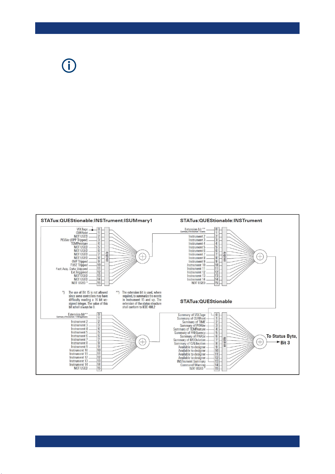
Additional Basics on Remote Control
R&S
®
NGL200/NGM200
187User Manual 1178.8736.02 ─ 09
Depending on the value of the read register, you can draw conclusions on the current
status of the device. For example, when the unit operates in constant voltage, the
result of the returned ISUM register is a decimal "2" which corresponds the binary
value of "0000000000000010".
Any part of a status register system can be read by query commands. A decimal value
is returned and represents the bit pattern of the requested register. Each SCPI register
is 16 bits wide and has various functions. The individual bits are independent, i.e. each
hardware status is assigned to a bit number.
Bits 9 to 12 are still "free" resp. unused (always return a "0"). Certain areas of the reg-
isters are not used. The SCPI standard defines only the "basic functions". Some devi-
ces offer an advanced functionality.
Each channel of the power supply is considered as separate "instrument" (SCPI stan-
dard definition). Therefore, e.g. the register
STATus:QUEStionable:INSTrument:ISUMary of the NGL202 or NGM202 is also
present two times (Isummary1 - Isummary2).
Description of the status register parts
The SCPI standard provides two different status registers:
Figure A-1: Structure of the status:QUEStionable register
Status Reporting System
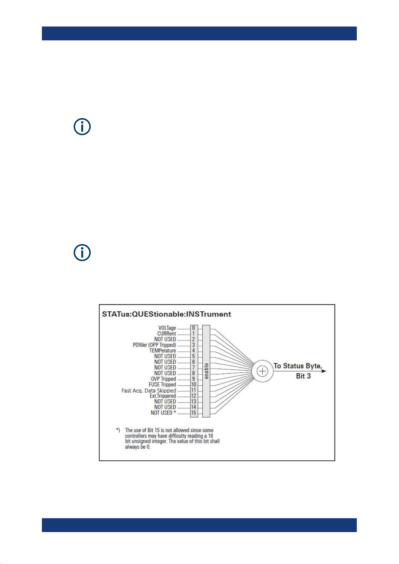
Additional Basics on Remote Control
R&S
®
NGL200/NGM200
188User Manual 1178.8736.02 ─ 09
CONDition
●
The CONDition register queries the actual state of the instrument. If you want to
query the constant voltage or current mode, you have to use the CONDition regis-
ter.
The CONDition register delivers a "1" (first bit set) in constant current mode (CC) and
a "2" (second bit set) in constant voltage mode (CV).
If the correct channel is selected and the red LED of the channel button lights up (CC
mode), the query of the CONDition register must deliver a "1".
Example:
STAT:QUES:ISUM1:COND?
EVENt
●
The EVENt status register is set (1) until it is queried. After reading (query), the
EVENt status register is set to zero.
The description of registers is only used for general explanation. Due to the complexity,
we recommend the general accessible SCPI standard document for more detailed
information.
For further description of the status register, see
Chapter 7.9, "Status Reporting Com-
mands"
, on page 175.
Figure A-2: Structure of the status:QUEStionable:INSTrument register
Status Reporting System

Additional Basics on Remote Control
R&S
®
NGL200/NGM200
189User Manual 1178.8736.02 ─ 09
Event Status Register (ESR) and Event Status Enable Register (ESE)
The ESR is defined in IEEE 488.2. It can be compared with the EVENt part of an SCPI
register. The event status register can be read out using the command *ESR?. The
ESE corresponds to the ENABle part of an SCPI register. If a bit is set in the ESE and
the associated bit in the ESR changes from 0 to 1, the ESB bit in the STB is set. The
ESE register can be set using the command *ESE and read using the command
*ESE?.
STATus:OPERation Register
In the CONDition part, this register contains information on which actions the instru-
ment is being executing or, in the EVENt part, information on which actions the instru-
ment has executed since the last reading. It can be read using the commands
STATus:OPERation:CONDition? or STATus:OPERation[:EVENt]?.
Bit No. Meaning
0 CALibrating
This bit is set as long as the instrument is performing a calibration.
1 to 3 Not used
4 MEASuring
This bit is set on event new measurement available.
5 to 9 Not used
10 Logging
This bit is set as long as "Logging" is enabled
11 Not used
12 FastLog
This bit is set once "FastLog" data is available
13 to
14
Not used
15 This bit is always 0
STATus:QUEStionable Register
This register contains information about different states which can occur. It can be read
using the commands STATus:QUEStionable:CONDition? and
STATus:QUEStionable[:EVENt]?. See
Figure A-1.
Table A-6: Bits of the STATus:QUEStionable register
Bit No. Meaning
0 Voltage
This bit is set while the instrument is in constant current mode (CC). The voltage is regula-
ted and the current is constant.
1 Current
This bit is set while the instrument is in constant voltage mode (CV). The current is variable
and the voltage is constant.
Status Reporting System
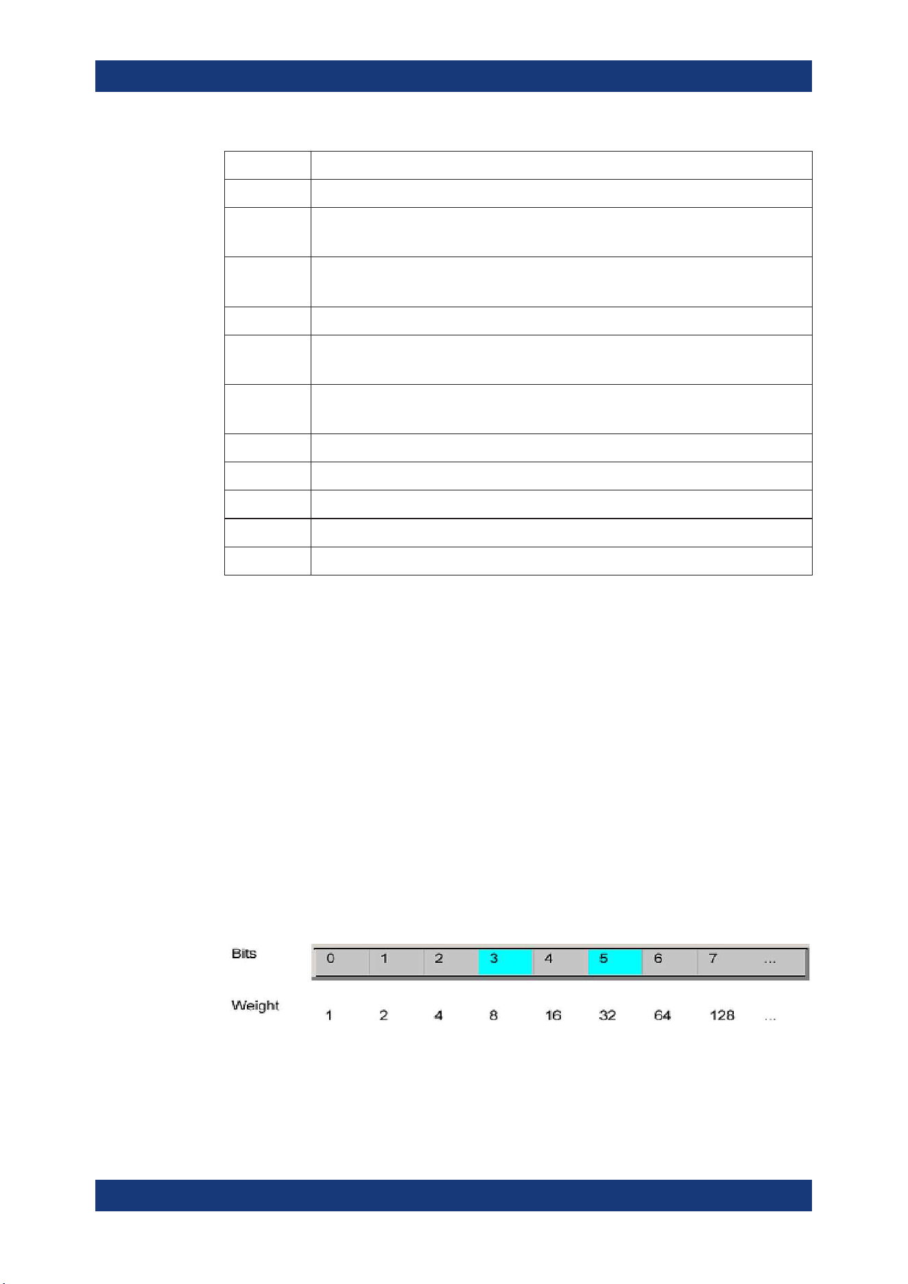
Additional Basics on Remote Control
R&S
®
NGL200/NGM200
190User Manual 1178.8736.02 ─ 09
Bit No. Meaning
2 Not used
3 POWer (OPP Tripped)
This bit is set if an over power protection has tripped.
4 Temperature overrange
This bit is set if an over temperature occurs.
5 to 8 Not used
9 OVP Tripped
This bit is set if the over voltage protection has tripped.
10 Fuse Tripped
This bit is set if the fuse protection has tripped.
11 Fast Acq. Data Skipped
12 Ext.Triggered
13 Sense Connection
14 Not used
15 This bit is always 0
Query of an instrument status
Each part of any status register can be read using queries.
There are two types of commands:
●
The common commands *ESR?, *IDN?, *STB? query the higher-level registers.
●
The commands of the STATus system query the SCPI registers
(STATus:QUEStionable)
The returned value is always a decimal number that represents the bit pattern of the
queried register. This number is evaluated by the controller program.
Decimal representation of a bit pattern (binary weights)
The STB and ESR registers contain 8 bits, the status registers 16 bits. The contents of
a status register are specified and transferred as a single decimal number. To make
this possible, each bit is assigned a weighted value. The decimal number is calculated
as the sum of the weighted values of all bits in the register that are set to 1.
Figure A-3: Decimal representation of a bit pattern
Status Reporting System

Additional Basics on Remote Control
R&S
®
NGL200/NGM200
191User Manual 1178.8736.02 ─ 09
Error Queue
Each error state in the instrument leads to an entry in the error queue. The entries of
the error queue are detailed plain text error messages. You can look them up in the
error log or via remote control using SYSTem:ERRor[:NEXT]?. Each call of
SYSTem:ERRor[:NEXT]? provides one entry from the error queue. If no error mes-
sages are stored, the instrument responds with 0, "No error".
Status Reporting System

List of Commands
R&S
®
NGL200/NGM200
192User Manual 1178.8736.02 ─ 09
List of Commands
[SOURce:]ALIMit[:STATe].............................................................................................................................. 108
[SOURce:]CURRent:PROTection:CLEar.......................................................................................................131
[SOURce:]CURRent:PROTection:DELay...................................................................................................... 132
[SOURce:]CURRent:PROTection:DELay:INITial...........................................................................................131
[SOURce:]CURRent:PROTection:LINK......................................................................................................... 132
[SOURce:]CURRent:PROTection:TRIPped?.................................................................................................133
[SOURce:]CURRent:PROTection:UNLink..................................................................................................... 133
[SOURce:]CURRent:PROTection[:STATe].....................................................................................................133
[SOURce:]CURRent[:LEVel][:IMMediate]:ALIMit:LOWer...............................................................................110
[SOURce:]CURRent[:LEVel][:IMMediate]:ALIMit[:UPPer]..............................................................................110
[SOURce:]CURRent[:LEVel][:IMMediate]:STEP[:INCRement]...................................................................... 116
[SOURce:]CURRent[:LEVel][:IMMediate][:AMPLitude]..................................................................................116
[SOURce:]POWer:PROTection:CLEar...........................................................................................................141
[SOURce:]POWer:PROTection:LEVel........................................................................................................... 141
[SOURce:]POWer:PROTection:TRIPped?.....................................................................................................142
[SOURce:]POWer:PROTection[:STATe].........................................................................................................140
[SOURce:]RESistance:STATe........................................................................................................................119
[SOURce:]RESistance[:LEVel][:IMMediate][:AMPLitude].............................................................................. 118
[SOURce:]VOLTage:DVM[:STATe].................................................................................................................127
[SOURce:]VOLTage:PROTection:CLEar........................................................................................................138
[SOURce:]VOLTage:PROTection:LEVel........................................................................................................ 138
[SOURce:]VOLTage:PROTection:TRIPped?..................................................................................................139
[SOURce:]VOLTage:PROTection[:STATe]......................................................................................................138
[SOURce:]VOLTage:RAMP:DURation........................................................................................................... 156
[SOURce:]VOLTage:RAMP[:STATe].............................................................................................................. 155
[SOURce:]VOLTage[:LEVel][:IMMediate]:ALIMit:LOWer............................................................................... 109
[SOURce:]VOLTage[:LEVel][:IMMediate]:ALIMit[:UPPer].............................................................................. 109
[SOURce:]VOLTage[:LEVel][:IMMediate]:STEP[:INCRement].......................................................................114
[SOURce:]VOLTage[:LEVel][:IMMediate][:AMPLitude].................................................................................. 113
*CLS.................................................................................................................................................................96
*ESE................................................................................................................................................................ 96
*ESR?.............................................................................................................................................................. 97
*IDN?............................................................................................................................................................... 97
*OPC................................................................................................................................................................97
*OPT?.............................................................................................................................................................. 97
*RST................................................................................................................................................................ 97
*SRE................................................................................................................................................................ 98
*STB?...............................................................................................................................................................98
*TRG................................................................................................................................................................98
*TST?...............................................................................................................................................................98
*WAI.................................................................................................................................................................98
APPLy............................................................................................................................................................ 119
ARBitrary:BEHavior:END...............................................................................................................................151
ARBitrary:CLEar............................................................................................................................................ 152
ARBitrary:DATA............................................................................................................................................. 152
ARBitrary:FNAMe.......................................................................................................................................... 152
ARBitrary:LOAD.............................................................................................................................................153

List of Commands
R&S
®
NGL200/NGM200
193User Manual 1178.8736.02 ─ 09
ARBitrary:REPetitions....................................................................................................................................153
ARBitrary:RESTore........................................................................................................................................ 153
ARBitrary:SAVE............................................................................................................................................. 153
ARBitrary:STARt............................................................................................................................................ 154
ARBitrary:STOP.............................................................................................................................................154
ARBitrary:TRANsfer.......................................................................................................................................154
ARBitrary:TRIGgered:MODE.........................................................................................................................154
ARBitrary:TRIGgered[:STATe]....................................................................................................................... 155
ARBitrary[:STATe].......................................................................................................................................... 151
BATTery:MODel:CAPacity............................................................................................................................. 164
BATTery:MODel:CLEar.................................................................................................................................. 164
BATTery:MODel:CURRent:LIMit:EOC........................................................................................................... 163
BATTery:MODel:CURRent:LIMit:EOD........................................................................................................... 164
BATTery:MODel:CURRent:LIMit:REGular..................................................................................................... 164
BATTery:MODel:DATA................................................................................................................................... 164
BATTery:MODel:FNAMe................................................................................................................................ 165
BATTery:MODel:ISOC................................................................................................................................... 165
BATTery:MODel:LOAD.................................................................................................................................. 165
BATTery:MODel:SAVE...................................................................................................................................166
BATTery:MODel:TRANsfer............................................................................................................................ 166
BATTery:SIMulator:CAPacity:LIMit................................................................................................................ 160
BATTery:SIMulator:CAPacity?....................................................................................................................... 160
BATTery:SIMulator:CURRent:LIMit:EOC....................................................................................................... 161
BATTery:SIMulator:CURRent:LIMit:EOD....................................................................................................... 161
BATTery:SIMulator:CURRent:LIMit:REGular................................................................................................. 161
BATTery:SIMulator:CURRent:LIMit?..............................................................................................................160
BATTery:SIMulator:CURRent?.......................................................................................................................160
BATTery:SIMulator:RESistance?................................................................................................................... 161
BATTery:SIMulator:SOC................................................................................................................................ 161
BATTery:SIMulator:TVOLtage?......................................................................................................................162
BATTery:SIMulator:VOC:EMPTy?..................................................................................................................162
BATTery:SIMulator:VOC:FULL?.................................................................................................................... 162
BATTery:SIMulator:VOC?.............................................................................................................................. 162
BATTery:SIMulator[:ENABle]......................................................................................................................... 163
BATTery:STATus?..........................................................................................................................................163
DATA:DATA?..................................................................................................................................................168
DATA:DELete.................................................................................................................................................168
DATA:LIST?................................................................................................................................................... 169
DATA:POINts?............................................................................................................................................... 169
DIO:FAULt:CHANnel......................................................................................................................................156
DIO:FAULt:SIGNal......................................................................................................................................... 158
DIO:FAULt:SOURce...................................................................................................................................... 157
DIO:FAULt[:STATe]........................................................................................................................................ 157
DIO:OUTPut:SIGNal......................................................................................................................................159
DIO:OUTPut:SOURce................................................................................................................................... 158
DIO:OUTPut[:STATe]..................................................................................................................................... 158
DISPlay:BRIGhtness......................................................................................................................................101
DISPlay[:WINDow]:TEXT:CLEar....................................................................................................................102
DISPlay[:WINDow]:TEXT[:DATA].................................................................................................................. 102
FLOG:DATA?................................................................................................................................................. 169

List of Commands
R&S
®
NGL200/NGM200
194User Manual 1178.8736.02 ─ 09
FLOG:FILE:DURation....................................................................................................................................170
FLOG:FILE:TPARtition...................................................................................................................................171
FLOG:SRATe................................................................................................................................................. 170
FLOG:TARGet............................................................................................................................................... 171
FLOG:TRIGgered.......................................................................................................................................... 170
FLOG[:STATe]................................................................................................................................................171
FUSE:DELay:INITial...................................................................................................................................... 134
FUSE:DELay[:BLOWing]............................................................................................................................... 134
FUSE:LINK.................................................................................................................................................... 135
FUSE:TRIPped?............................................................................................................................................ 135
FUSE:UNLink.................................................................................................................................................135
FUSE[:STATe]................................................................................................................................................ 135
HCOPy:DATA?...............................................................................................................................................171
HCOPy:SIZE:X?............................................................................................................................................ 171
HCOPy:SIZE:Y?............................................................................................................................................ 172
INSTrument:NSELect.................................................................................................................................... 106
INSTrument[:SELect]..................................................................................................................................... 107
INTerfaces:USB:CLASs................................................................................................................................. 142
LOG:COUNt...................................................................................................................................................172
LOG:DURation...............................................................................................................................................173
LOG:FNAMe?................................................................................................................................................ 173
LOG:INTerval................................................................................................................................................. 173
LOG:MODE....................................................................................................................................................174
LOG:STIMe....................................................................................................................................................174
LOG:TRIGgered.............................................................................................................................................175
LOG[:STATe].................................................................................................................................................. 172
MEASure:VOLTage:DVM?.............................................................................................................................148
MEASure[:SCALar]:CURRent[:DC]:AVG?..................................................................................................... 145
MEASure[:SCALar]:CURRent[:DC]:MAX?.....................................................................................................145
MEASure[:SCALar]:CURRent[:DC]:MIN?......................................................................................................145
MEASure[:SCALar]:CURRent[:DC]:STATistic?..............................................................................................146
MEASure[:SCALar]:CURRent[:DC]?............................................................................................................. 145
MEASure[:SCALar]:ENERgy:RESet..............................................................................................................143
MEASure[:SCALar]:ENERgy:STATe..............................................................................................................144
MEASure[:SCALar]:ENERgy:UNIT................................................................................................................144
MEASure[:SCALar]:ENERgy?....................................................................................................................... 143
MEASure[:SCALar]:POWer:AVG?.................................................................................................................146
MEASure[:SCALar]:POWer:MAX?................................................................................................................ 146
MEASure[:SCALar]:POWer:MIN?..................................................................................................................147
MEASure[:SCALar]:POWer:STATistic?......................................................................................................... 147
MEASure[:SCALar]:POWer?......................................................................................................................... 146
MEASure[:SCALar]:STATistic:COUNt?..........................................................................................................144
MEASure[:SCALar]:STATistic:RESet.............................................................................................................145
MEASure[:SCALar]:STATistic:RESet.............................................................................................................145
MEASure[:SCALar][:POWer]:AVG?...............................................................................................................146
MEASure[:SCALar][:POWer]:MAX?.............................................................................................................. 146
MEASure[:SCALar][:POWer]:MIN?................................................................................................................147
MEASure[:SCALar][:VOLTage][:DC]:AVG?....................................................................................................147
MEASure[:SCALar][:VOLTage][:DC]:MAX?................................................................................................... 147
MEASure[:SCALar][:VOLTage][:DC]:MIN?.................................................................................................... 148

List of Commands
R&S
®
NGL200/NGM200
195User Manual 1178.8736.02 ─ 09
MEASure[:SCALar][:VOLTage][:DC]:STATistic?............................................................................................ 148
MEASure[:SCALar][:VOLTage][:DC]?............................................................................................................ 147
OUTPut:DELay:DURation..............................................................................................................................122
OUTPut:DELay[:STATe].................................................................................................................................123
OUTPut:FTResponse.................................................................................................................................... 123
OUTPut:GENeral[:STATe]..............................................................................................................................122
OUTPut:IMPedance.......................................................................................................................................124
OUTPut:IMPedance:STATe........................................................................................................................... 124
OUTPut:MODE.............................................................................................................................................. 125
OUTPut:SELect............................................................................................................................................. 125
OUTPut:TRIGgered....................................................................................................................................... 126
OUTPut:TRIGgered:BEHavior.......................................................................................................................126
OUTPut:TRIGgered[:STATe]..........................................................................................................................126
OUTPut[:STATe].............................................................................................................................................122
READ?...........................................................................................................................................................120
SENSe:CURRent:RANGe:AUTO.................................................................................................................. 127
SENSe:CURRent:RANGe[:UPPer]................................................................................................................128
SENSe:VOLTage:RANGe:AUTO................................................................................................................... 128
SENSe:VOLTage:RANGe[:UPPer]................................................................................................................ 128
STATus:OPERation:INSTrument:CONDition?............................................................................................... 175
STATus:OPERation:INSTrument:ENABle......................................................................................................176
STATus:OPERation:INSTrument:ISUMmary<Channel>:CONDition?............................................................175
STATus:OPERation:INSTrument:ISUMmary<Channel>:ENABle.................................................................. 176
STATus:OPERation:INSTrument:ISUMmary<Channel>:NTRansition...........................................................176
STATus:OPERation:INSTrument:ISUMmary<Channel>:PTRansition........................................................... 177
STATus:OPERation:INSTrument:ISUMmary<Channel>[:EVENt]?................................................................176
STATus:OPERation:INSTrument:NTRansition...............................................................................................176
STATus:OPERation:INSTrument:PTRansition...............................................................................................177
STATus:OPERation:INSTrument[:EVENt]?....................................................................................................176
STATus:QUEStionable:INSTrument:CONDition?.......................................................................................... 178
STATus:QUEStionable:INSTrument:ENABle.................................................................................................178
STATus:QUEStionable:INSTrument:ISUMmary<Channel>:CONDition?.......................................................178
STATus:QUEStionable:INSTrument:ISUMmary<Channel>:ENABle............................................................. 178
STATus:QUEStionable:INSTrument:ISUMmary<Channel>:NTRansition...................................................... 179
STATus:QUEStionable:INSTrument:ISUMmary<Channel>:PTRansition...................................................... 179
STATus:QUEStionable:INSTrument:ISUMmary<Channel>[:EVENt]?........................................................... 178
STATus:QUEStionable:INSTrument:NTRansition..........................................................................................179
STATus:QUEStionable:INSTrument:PTRansition..........................................................................................179
STATus:QUEStionable:INSTrument[:EVENt]?...............................................................................................178
SYSTem:BEEPer:CURRent:STATe................................................................................................................. 99
SYSTem:BEEPer:PROTection:STATe..............................................................................................................99
SYSTem:BEEPer:PROTection[:IMMediate]..................................................................................................... 99
SYSTem:BEEPer:STATe................................................................................................................................100
SYSTem:DATE...............................................................................................................................................101
SYSTem:KEY:BRIGhtness.............................................................................................................................100
SYSTem:LOCal..............................................................................................................................................100
SYSTem:REMote...........................................................................................................................................100
SYSTem:RWLock.......................................................................................................................................... 100
SYSTem:TIME............................................................................................................................................... 101
TRIGger[:SEQuence][:IMMediate]:SOURce..................................................................................................103

List of Commands
R&S
®
NGL200/NGM200
196User Manual 1178.8736.02 ─ 09
TRIGger[:SEQuence][:IMMediate]:SOURce:DIO:CHANnel.......................................................................... 103
TRIGger[:SEQuence][:IMMediate]:SOURce:DIO:PIN................................................................................... 104
TRIGger[:SEQuence][:IMMediate]:SOURce:OMODe....................................................................................104
TRIGger[:SEQuence][:IMMediate]:SOURce:OMODe:CHANnel....................................................................105
TRIGger[:SEQuence][:IMMediate]:SOURce:OUTPut:CHANnel....................................................................105
TRIGger[:STATe]............................................................................................................................................102

Index
R&S
®
NGL200/NGM200
197User Manual 1178.8736.02 ─ 09
Index
A
Activate channel output ..................................................... 45
Activating the channels output .......................................... 26
Advanced features
Arbitrary ...................................................................... 67
Ramp .......................................................................... 67
Advanced operating commands
Arbitrary .................................................................... 149
Battery Simulation ..................................................... 159
Digital I/O .................................................................. 156
Ramp ........................................................................ 155
Alert beep .......................................................................... 92
Arbitrary .............................................................................67
B
Battery simulator ............................................................... 54
Battery model editor .................................................... 56
C
Channel display area
Operating mode .......................................................... 32
Clear status
Remote ....................................................................... 96
Command sequence
Remote ....................................................................... 98
Command sequence and synchronization ...................... 185
Configuration commands
Channel selection ..................................................... 106
Combined setting of voltage and current setting ....... 119
Current setting ...........................................................114
OCP setting .............................................................. 129
OPP setting ............................................................... 139
Output setting ........................................................... 120
OVP setting ............................................................... 136
Range/DVM setting ................................................... 126
Resistance setting ..................................................... 117
Safety limit setting ..................................................... 107
USB class setting ...................................................... 142
Voltage setting ........................................................... 111
Constant resistance .......................................................... 46
CSV settings ..................................................................... 76
Customer support ..............................................................28
D
Data logging ...................................................................... 73
CSV settings ............................................................... 73
Date ...................................................................................93
Default values
Remote ....................................................................... 97
Delivery package contents ................................................ 19
Device documentation .......................................................95
Device/Channel menu window .......................................... 37
Digital I/O .......................................................................... 62
Digital voltmeter ................................................................ 52
Measurement ranges .................................................. 53
Display brightness ............................................................. 92
Display overview ............................................................... 29
Channel display area .................................................. 32
Status bar information ................................................. 29
Documentation overview ..................................................... 9
DVM .................................................................................. 52
E
Electrostatic discharge ...................................................... 15
ESD ................................................................................... 15
Event status enable register (ESE)
Remote ....................................................................... 96
Event status register (ESR)
Remote ....................................................................... 97
F
Factory default settings ..................................................... 81
Fast transient response .....................................................47
FastLog ............................................................................. 75
File manager
Copy ........................................................................... 80
Delete ......................................................................... 80
Front panel
Display ........................................................................ 21
Menu control keys ....................................................... 21
Output and channel keys ............................................ 22
Output terminals ......................................................... 22
Power key ................................................................... 22
Rotary knob and back keys ........................................ 21
USB connector ............................................................ 22
Front panel keys ................................................................37
Menu controls ............................................................. 37
Navigation controls ..................................................... 40
Output and channel controls ....................................... 41
Settings key ................................................................ 37
G
General instrument settings .............................................. 90
Appearance settings ................................................... 92
Data and time ............................................................. 93
Device information ...................................................... 94
Licenses management ................................................ 90
Sound settings ............................................................ 92
Update device ............................................................. 94
Getting Started .................................................................... 9
Graphical view window ...................................................... 78
I
Identification
Remote ....................................................................... 97
Important notes
Ambient conditions ..................................................... 12
Limits .......................................................................... 14
Mains voltage .............................................................. 13
Measurement categories ............................................ 13
Symbols ...................................................................... 12
Instrument tour .................................................................. 20
Overview of controls ................................................... 20
switching on NGL/NGM ............................................. 24
Intended operation ............................................................ 17
Interfaces .......................................................................... 83
K
Key brightness .................................................................. 92

Index
R&S
®
NGL200/NGM200
198User Manual 1178.8736.02 ─ 09
M
Maintenance
Cleaning ...................................................................... 27
Menu
Channel menu ............................................................ 39
Device menu ............................................................... 37
Menu controls ....................................................................37
Home key .................................................................... 37
Settings key ................................................................ 37
User key ...................................................................... 40
Message and command structure
Messages ................................................................. 180
SCPI command structure .......................................... 181
Mode
Operation modes ........................................................ 42
N
Navigation controls ............................................................40
Back key ..................................................................... 41
Rotary knob ................................................................ 41
Network
GPIB ........................................................................... 89
LAN ............................................................................. 85
USB ............................................................................ 88
Wireless LAN .............................................................. 87
Network connection ...........................................................84
O
Open source acknowledgment (OSA) ............................... 10
Operation complete
Remote ....................................................................... 97
Operation modes
Constant current (CC) ................................................. 42
Constant resistance (CR) ........................................... 43
Constant voltage (CV) ................................................ 42
Options
Identification (remote) ................................................. 97
Output ............................................................................... 48
Delay ........................................................................... 49
Impedance .................................................................. 48
Output delay ............................................................... 49
Output mode ............................................................... 51
Trigger events ............................................................. 50
Output and channel controls ............................................. 41
Overcurrent protection ...................................................... 58
Overpower protection ........................................................ 60
Overview of controls
Front panel .................................................................. 20
Rear panel .................................................................. 22
Overvoltage protection ...................................................... 59
P
Power derating .................................................................. 41
Protection
Fuse linking ................................................................. 58
Overcurrent protection ................................................ 58
Overpower protection ................................................. 58
Overvoltage protection ................................................ 58
Safety limits ................................................................ 58
Putting into operation ....................................................... 15
Intended operation ...................................................... 17
Safety .......................................................................... 16
Unpacking and checking the instrument ..................... 19
R
Ramp .................................................................................70
Ranges .............................................................................. 52
Rear panel
AC inlet with fuse holder ............................................. 23
Channel connectors .................................................... 23
Digital I/O connector ................................................... 24
Ethernet connector ..................................................... 23
IEEE-488 (GPIB) interface .......................................... 23
USB connectors .......................................................... 23
Voltage selector .......................................................... 23
Recall ................................................................................ 81
Release notes ................................................................... 10
Remote control commands ............................................... 96
Advanced operating commands ............................... 149
Common setting commands ....................................... 96
Configuration commands .......................................... 105
Data and file management commands ..................... 166
Display commands ................................................... 101
Measurement commands ......................................... 142
Status reporting commands ...................................... 175
System settings commands ........................................ 99
Trigger commands .................................................... 102
Reset values
Remote ....................................................................... 97
S
Safety ................................................................................ 16
Safety instructions ............................................................... 9
Safety limits ....................................................................... 61
Save .................................................................................. 81
Screenshot ........................................................................ 72
Selecting channels ............................................................ 44
Self-test
Remote ....................................................................... 98
Service request enable register (SRE)
Remote ....................................................................... 98
Set voltage and current ..................................................... 44
Setting the output voltage and current limit ....................... 26
Setting up the instrument .................................................. 19
Bench operation .......................................................... 19
Rack mounting ............................................................ 20
Status bar information
Channel status bar ...................................................... 31
Device status bar ........................................................ 30
Status byte
Remote ................................................................. 96, 98
Status reporting system .................................................. 186
Structure of a SCPI status register ........................... 186
T
Time .................................................................................. 93
Trigger ............................................................................... 62
Trigger IO system .............................................................. 63
Trigger-in signals ........................................................ 63
Trigger-out signals ...................................................... 64
Trying out the instrument
Activating the channels output .................................... 25
Setting the output voltage and current limit ................ 25
U
Unpacking and checking the instrument ........................... 19
User button key ................................................................. 71

Index
R&S
®
NGL200/NGM200
199User Manual 1178.8736.02 ─ 09
User manual ........................................................................ 9
Using the touchscreen ...................................................... 33
Accessing functionality using shortcuts ...................... 35
Accessing functionality using the settings button ....... 33
Expand/Collapse button .............................................. 35
Input data .................................................................... 36
Using gestures ............................................................ 33
W
Wait
Remote ....................................................................... 98
Welcome to R&S NGL/NGM ............................................. 11