Data Sheet
Version 02.00
High precision source and sink
R&S®NGL200
POWER SUPPLY SERIES
AT A GLANCE
Thanks to their high accuracy and fast load recovery time, the R&S®NGL200 power supplies are perfect for
challenging applications. Their two-quadrant architecture allows them to function both as a source and a
sink to simulate batteries and loads. Their short recovery times enable them to handle fast load changes
that occur for example when mobile communications devices switch from sleep mode to transmit mode.
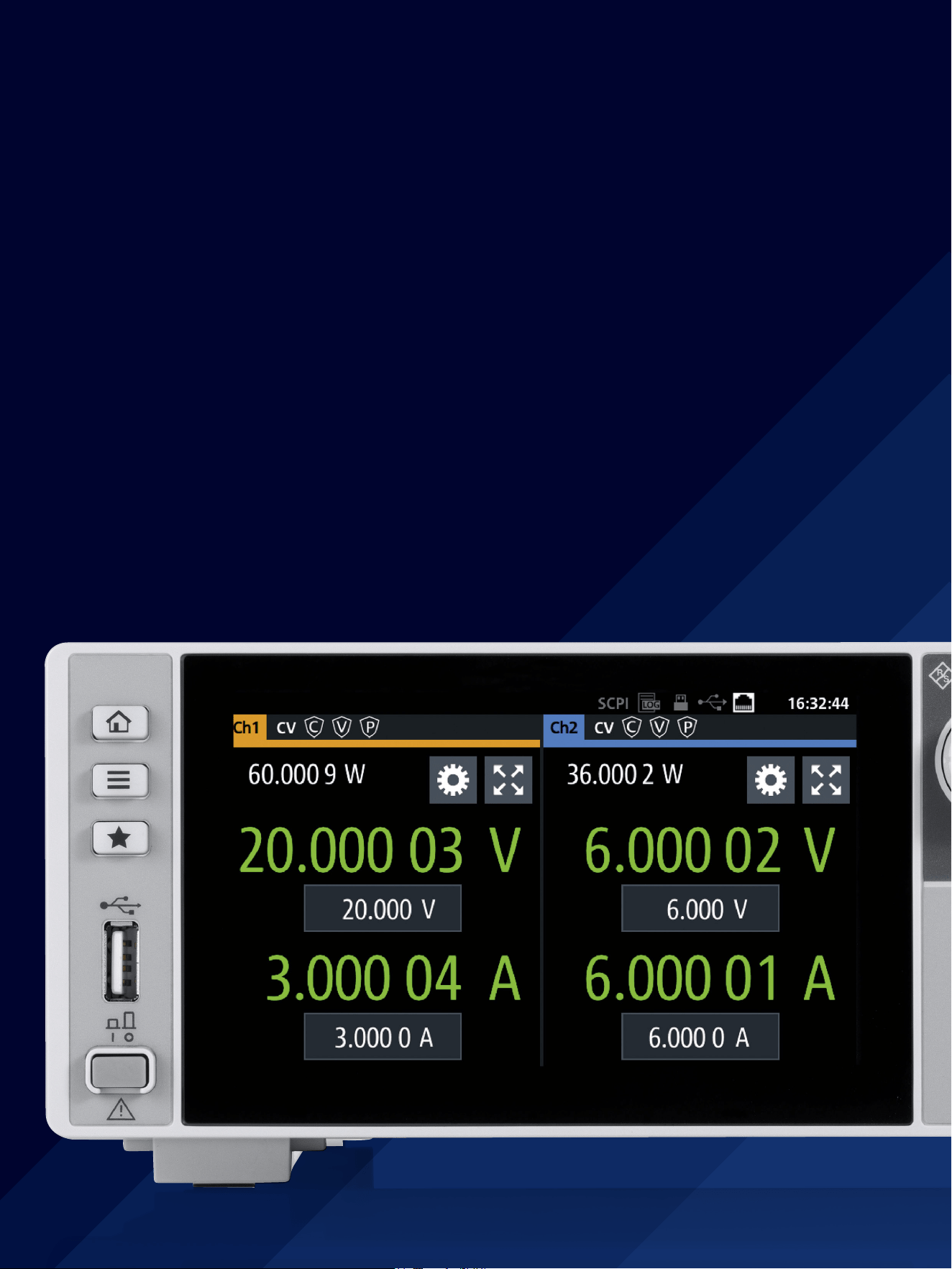
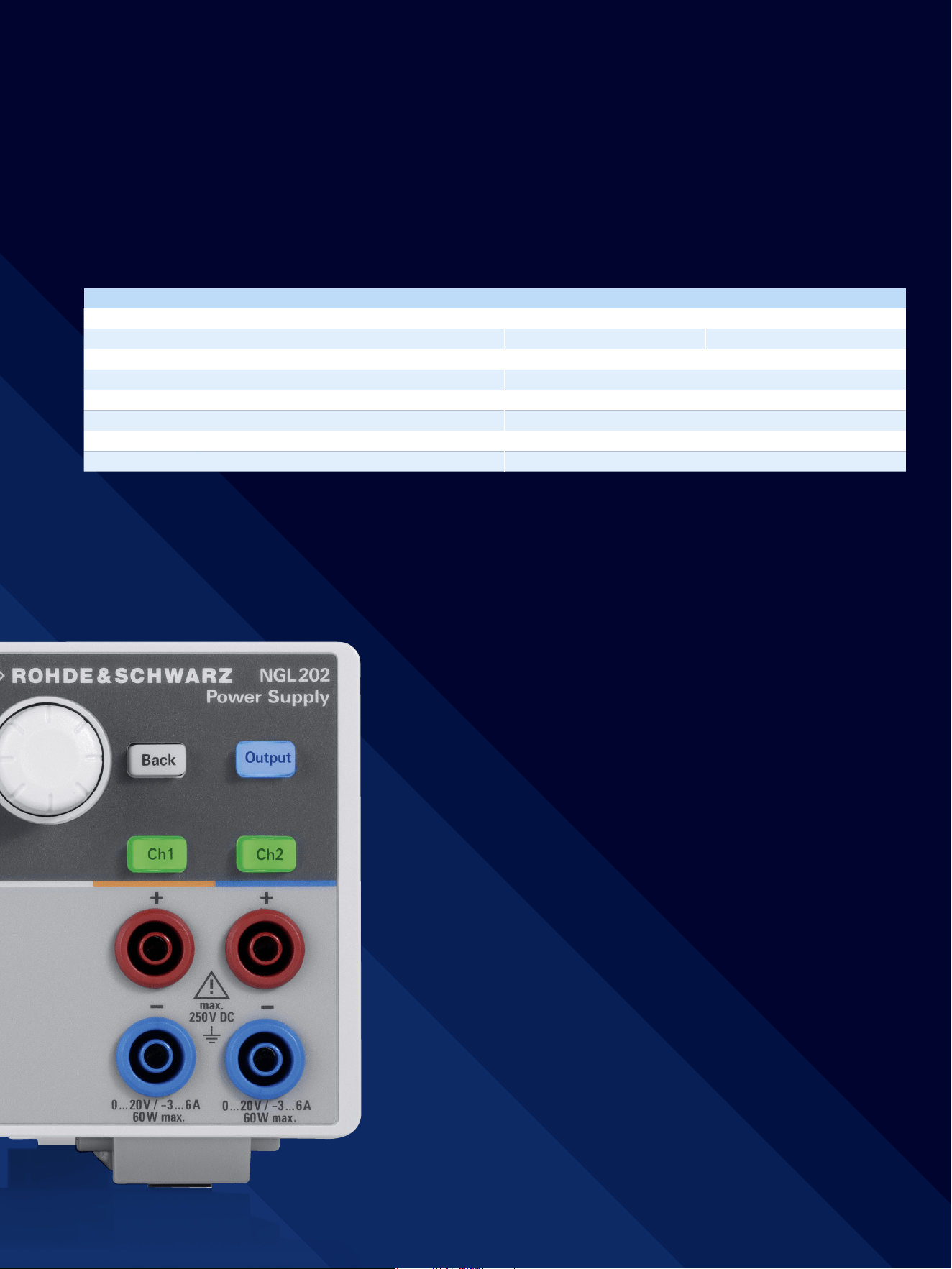
The single-channel R&S®NGL201 and the two-channel
R&S®NGL202 deliver up to 60W of output power per
channel. The output channels are floating, galvanically iso-
lated and protected against overload and short circuits.
Thanks to their fast recovery time of <30µs and minimum
overshoot even during a demanding load change, the
R&S®NGL200 power supplies are ideal for powering IoT
devices and other battery-operated devices.
With a resolution of up to 6 ½ digits when measuring
voltage, current and power, the R&S®NGL200 power sup-
plies are perfect for characterizing devices that have low
power consumption in standby mode and high current
in full load operation. In many cases, an additional digital
multimeter is no longer necessary.
The linear two-quadrant design of the output stages allows
the R&S®NGL200 power supply series to operate as a
source and sink with minimum residual ripple and noise,
ideally supporting the development of power amplifiers
and MMICs.
2
BENEFITS
Model overview
Parameter R&S®NGL201 R&S®NGL202
Number of output channels 1 2
Total output power 60 W 120 W
Maximum output power per channel 60 W
Output voltage per channel 0 V to 20 V
Maximum output current per channel ≤ 6 V: 6 A, > 6 V: 3 A
Load recovery time < 30 μs
Maximum power and current per channel when used as a load 60 W, 3 A
Rohde & Schwarz R&S®NGL200 Power Supply Series 3
Technology for challenging tasks
►
page 5
Easy operation
►
page 8
Ideal for use in labs and testsystems
►
page 10
4
Basic power supplies
►
Affordable, quiet and stable
►
For manual operation and simple computer-controlled
operation
►
Used in education, on the bench and in system racks
Performance power supplies
►
When speed, accuracy and advanced programming
features are vital to test performance
►
Features such as DUT protection, fast programming
times and downloadable V and I sequences
►
Used in labs and ATE applications
Specialty power supplies
►
Tailored to specic applications
►
Unique features such as
–
Emulation of unique battery characteristics
–
Electronic loads to accurately sink current and
dissipate power in a controlled manner
►
Used in labs and ATE environments
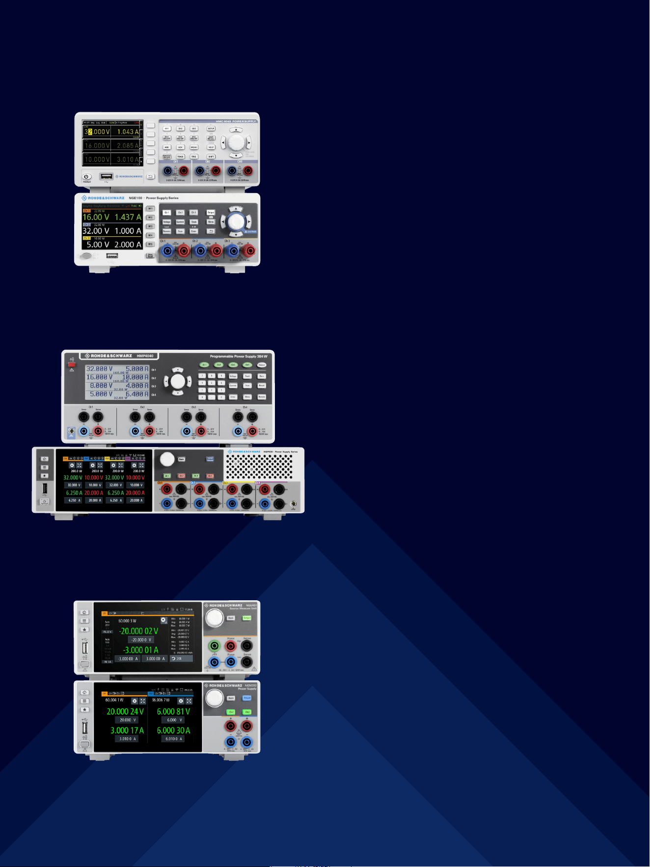
R&S®HMC8043 power supply and
R&S®NGE100B three-channel power supply
R&S®HMP4040 and R&S®NGP814
four-channel power supplies
R&S®NGU401 single-channel SMU and
R&S®NGM202 two-channel power supply
DIFFERENT POWER SUPPLY CLASSES
Rohde & Schwarz R&S®NGL200 Power Supply Series 5
TECHNOLOGY FOR CHALLENGING TASKS
Minimum residual ripple and low noise
Advanced electronic circuitry is often very complex and
sensitive to interference on the supply lines. In order to
supply interference-free voltage to such sensitive DUTs,
the power supplies must provide extremely stable output
voltages and currents. All types of ripple and noise need to
be avoided. The R&S®NGL200 power supplies have linear
regulation and are ideal for sensitive DUTs.
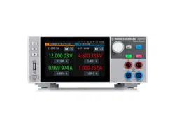
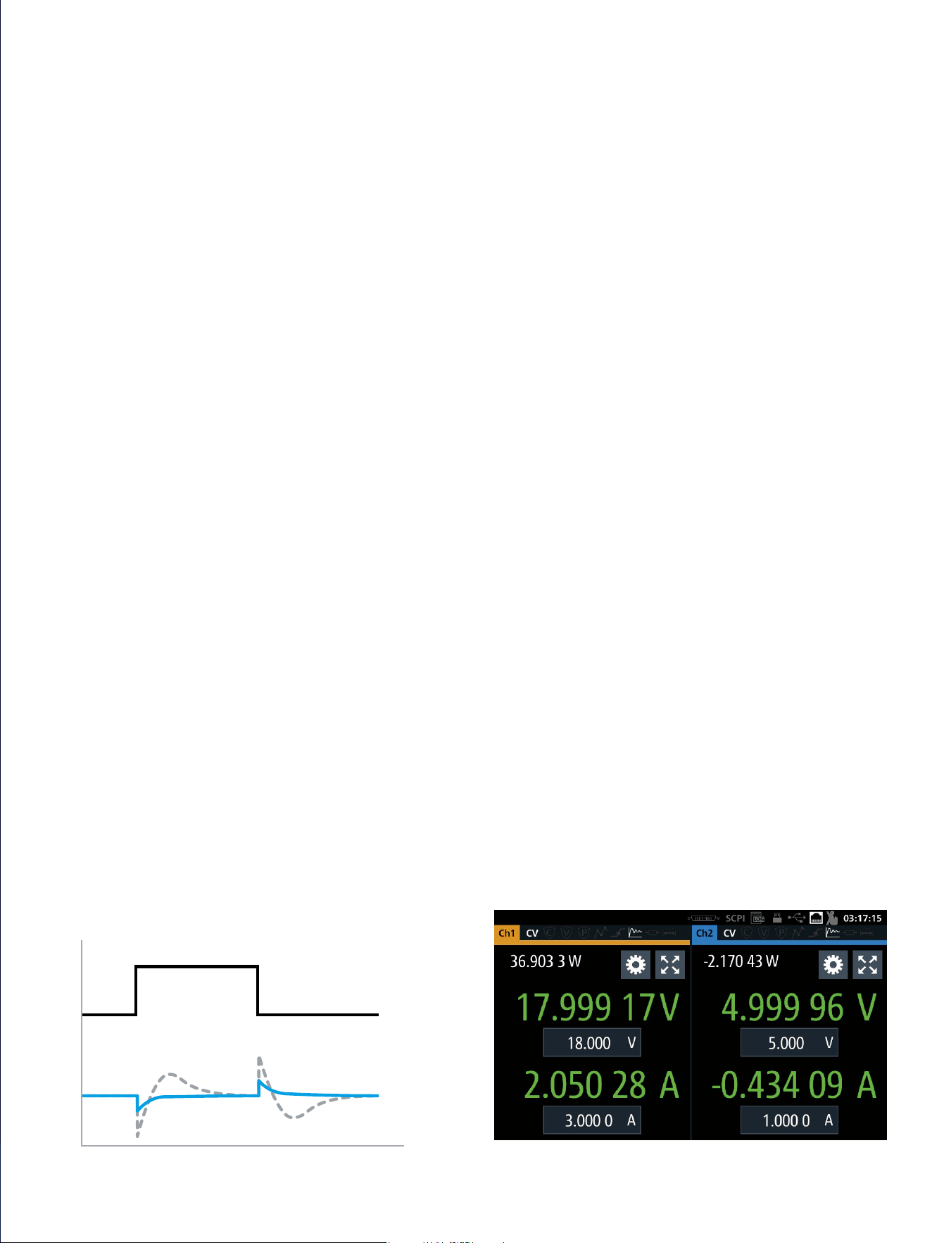
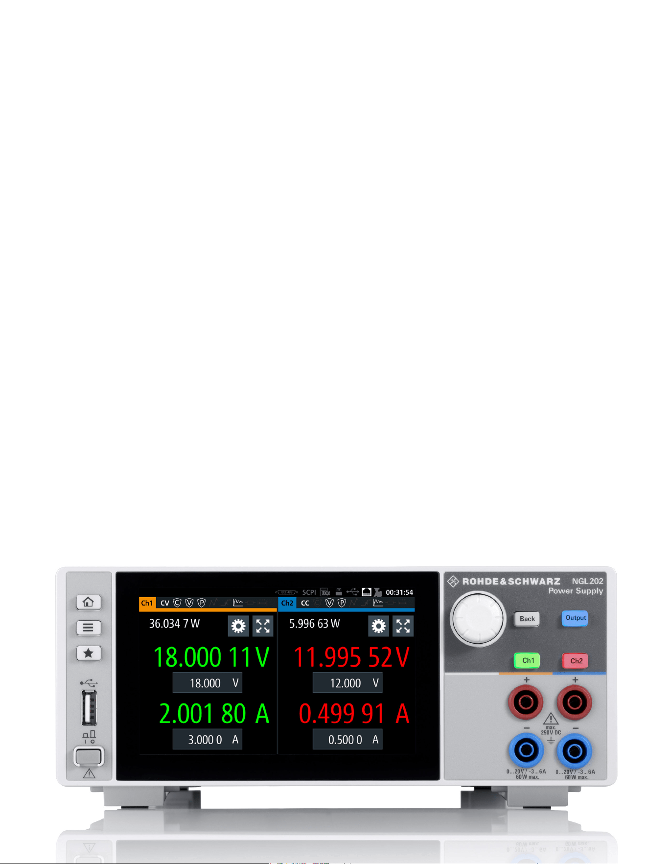
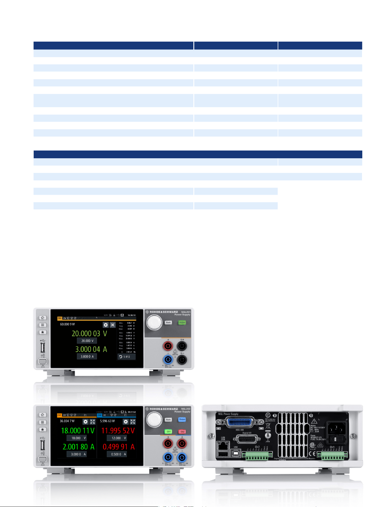
The measured currents and voltages are displayed with 6 ½ digit resolution. The
power supply automatically switches from source to sink mode. In the example,
channel 2 is operating as a load. This is indicated by a negative current reading.
Fast load regulation
Consumer electronics such as mobile phones and IoT
devices require very little power in sleep mode. However,
the current increases abruptly as soon as the device
switches to transmit mode. A power supply used to power
such DUTs must be capable of handling load changes
from a few µA to the ampere range without creating
voltage drops or overshoots.
The R&S®NGL200 power supplies have a new circuit
design that allows the user to determine how the power
supply regulates load changes. The “Fast” default set-
ting is optimized for speed, achieving recovery times of
<30µs. Deactivating “Fast” slightly increases the recov-
ery time, focusing on preventing overshoots.
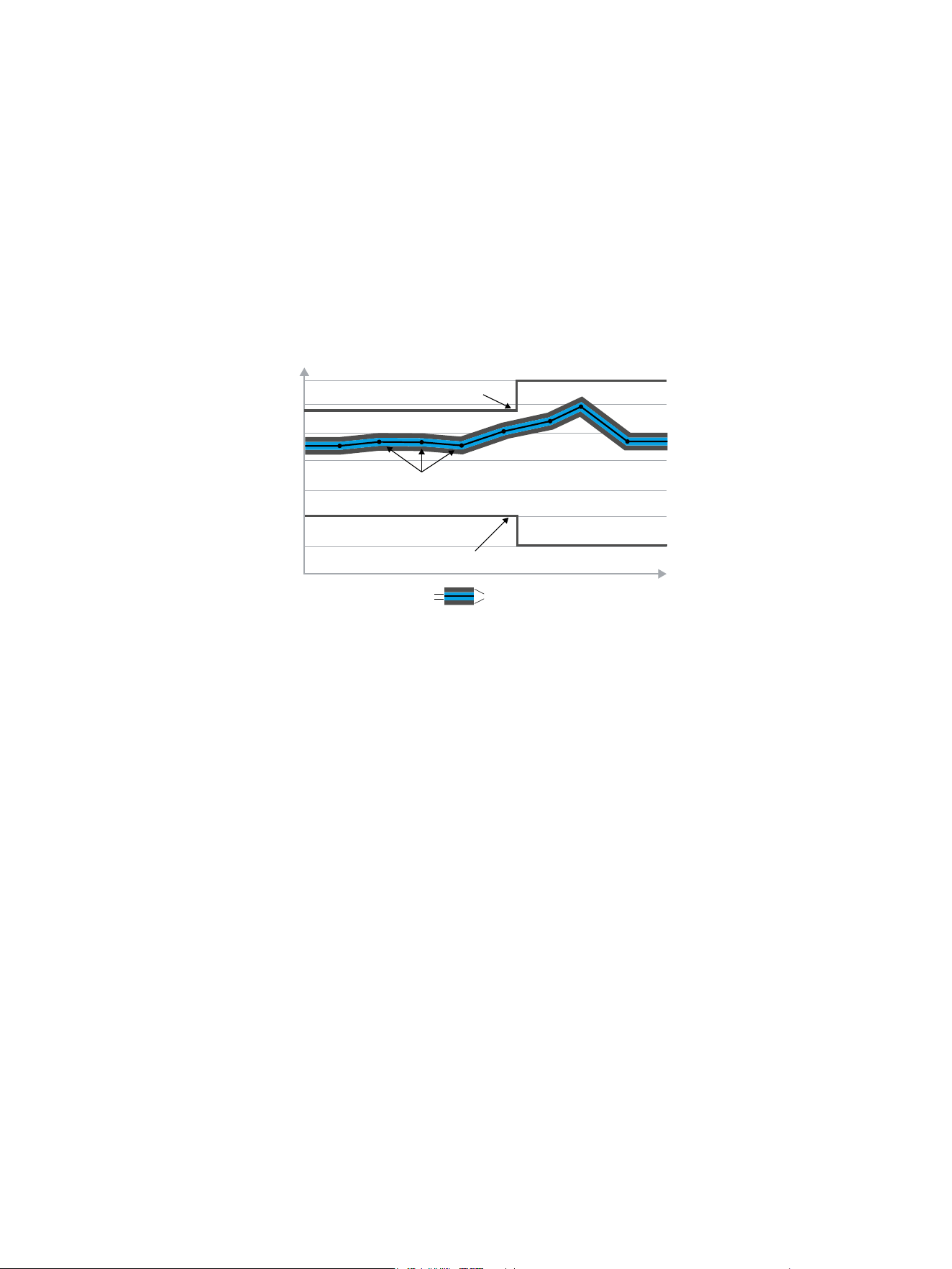
Optimized load recovery time
Under challenging load conditions, most power supplies respond with slow recovery times
and overshoots. Specially developed circuits in the R&S®NGL200 power supplies achieve a
load recovery time of < 30 µs with minimal overshoot, making them perfect for supplying
sensitive components.
Current
Voltage, R&S®NGL200
Voltage, standard power supply
Time
6
Readings with up to 6 ½ digit resolution
With a resolution of up to 6 ½ digits when measuring
voltage, current and power, the R&S®NGL200 power sup-
plies are perfect for characterizing devices that have low
power consumption in standby mode and high current
in full load operation. The entire measuring range is cov-
ered without having to switch ranges. This results in faster
measurements. In many cases, an additional digital multi-
meter is no longer necessary.
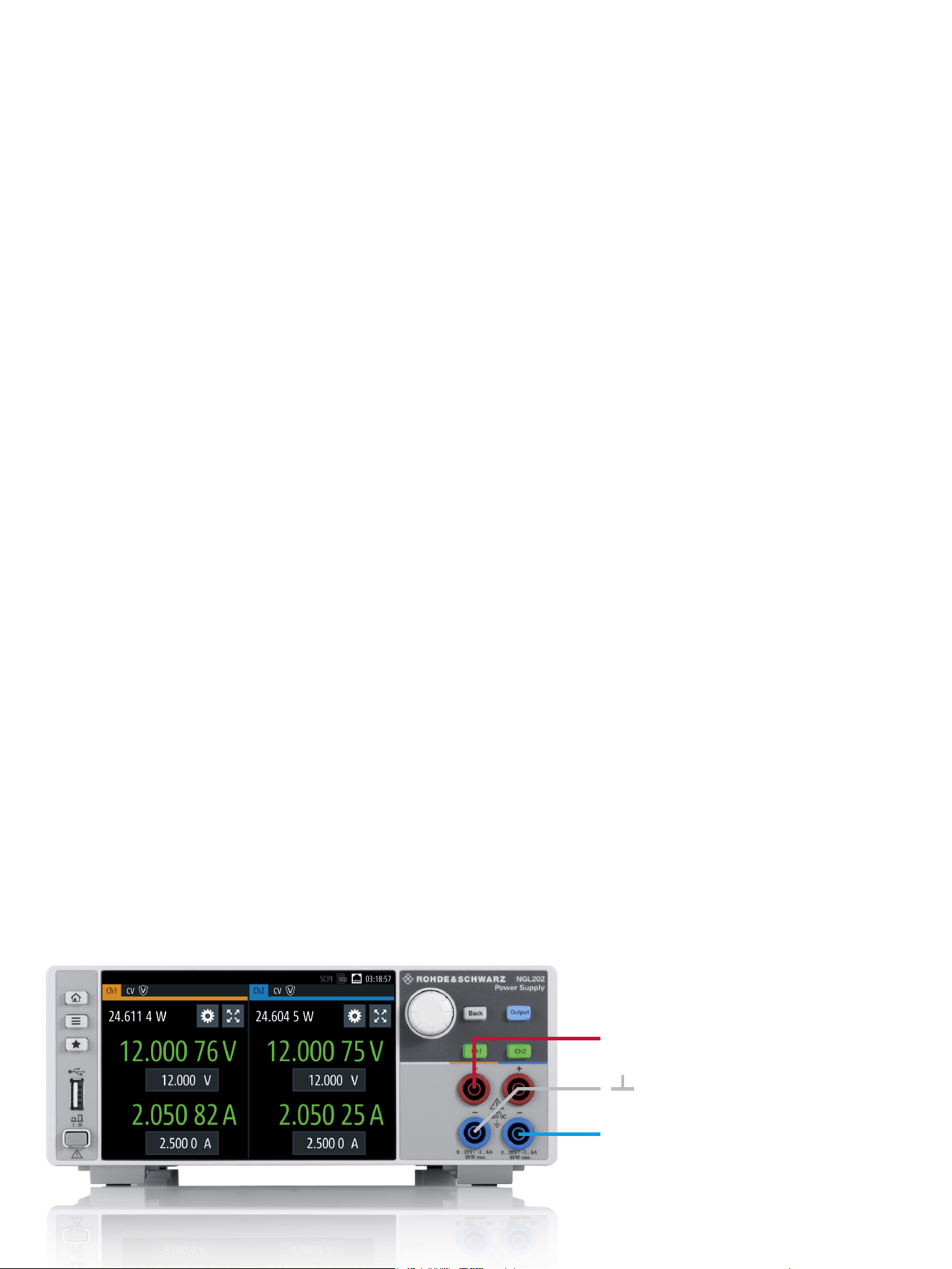
Galvanically isolated, floating channels
Both channels of the R&S®NGL202 are completely iso-
lated from each other and are not connected to chassis
ground. They can be used as independent power supplies
or be cascaded. The channels can be connected in parallel
to achieve higher currents or in series to achieve higher
voltages. Connecting the two channels makes it easy to
power bipolar circuits that might need +12V/–12V, for
example.
Output stage isolated with relays
Switching off an output channel of a standard power sup-
ply usually simply switches off the output voltage – the
output stage of the supply remains connected to the out-
put terminals. The R&S®NGL200 uses relays to isolate the
power supply circuits from the connector sockets.
Two quadrants: operates as source and sink
The two-quadrant architecture of the power supplies
allows them to function both as a source and a sink and
simulate batteries or loads. The power supply automati-
cally switches from source mode to sink mode. As soon
as the externally applied voltage exceeds the set nominal
voltage, current flows into the power supply. This is indi-
cated by a negative current reading.
Constant voltage, constant current and constant resistance
modes
Configuring and regulating the output voltage (constant
voltage mode) is the standard application for power sup-
plies. However, the R&S®NGL200 power supplies can also
be used in constant current mode, with each channel
separately configurable. If the configured current level is
exceeded, current limiting ensures that only the config-
ured current can flow. The output voltage is accordingly
reduced below the configured value. This prevents dam-
age to the test circuit in the event of a fault.
When operating as an electronic load, constant resistance
mode is also available. In this mode, the power supply
behaves like an adjustable resistance over the entire load
range. This makes it possible to simulate battery discharge
with a constant load resistance, for example.
Variable internal impedance
A power supply should have an internal impedance as
low as possible to suppress loading effects on the DUT.
However, there are applications where certain battery
types need to be simulated in a controlled manner or
where it is necessary to simulate the increase in internal
impedance as the battery discharges. The R&S®NGL200
power supplies support these applications due to their
adjustable internal impedance range.
Two channels can be connected together to supply bipolar circuits with, for example, +12V/–12V.
+12 V
–12 V
Rohde & Schwarz R&S®NGL200 Power Supply Series 7
Protection functions to safeguard instrument and DUT
The R&S®NGL200 power supplies provide protection func-
tions to make sure the DUT and the power supply are not
damaged in the event of a fault. The output channels are
protected against overload and short circuits. The maxi-
mum voltage, current and power can be set separately for
each channel. When a channel reaches the set limit, it is
automatically switched off and a message is displayed.
Overvoltage protection (OVP)
If the voltage exceeds the configured maximum value,
the channel is switched off and the corresponding symbol
flashes on the display.
Overcurrent protection (electronic fuse, OCP)
To better protect sensitive loads, the channels of
R&S®NGL200 power supplies provide electronic fuses that
can be set individually. If the channel current exceeds the
set current, the channel is automatically switched off and
the overcurrent symbol flashes.
In the two-channel R&S®NGL202, the electronic fuse can
be linked to the other channel (FuseLink function). Then
both channels are switched off as soon as the selected
channel reaches the maximum current value.
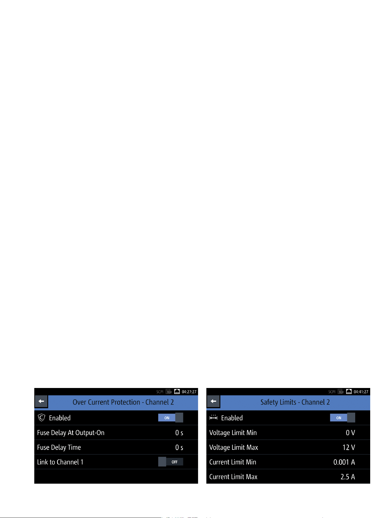
Electronic fuse with additional functions: “Fuse delay at output-on” specifies how
long the fuse remains inactive after the channel is activated. The sensitivity of the
fuse is specified using the “Fuse delay time”.
There are two settings to define the response behavior of
the electronic fuses. The “Fuse delay at output-on” speci-
fies how long the fuse remains inactive after the channel is
activated. The sensitivity of the fuse is specified using the
“Fuse delay time”. This allows users to modify the behav-
ior of the power supply to prevent a channel from being
switched off due to a short current spike during operation.
Overpower protection (OPP)
Alternatively, instead of the maximum voltage, the maxi-
mum power can be set and used as the switch-off
parameter.
Overtemperature protection (OTP)
The R&S®NGL200 power supplies have internal overtem-
perature protection that switches the power supply off if a
thermal overload is imminent.
Safety limits to safeguard the DUT
To prevent a DUT from being destroyed by a too high volt-
age, safety limits can be set on the R&S®NGL200 power
supplies. Before starting the actual measuring task, the
user can limit the power supply to values that are not
dangerous for the DUT.
The user can set safety limits to limit the adjustment range of the power supply and
prevent a DUT from being damaged due to accidentally using the wrong setting.

8
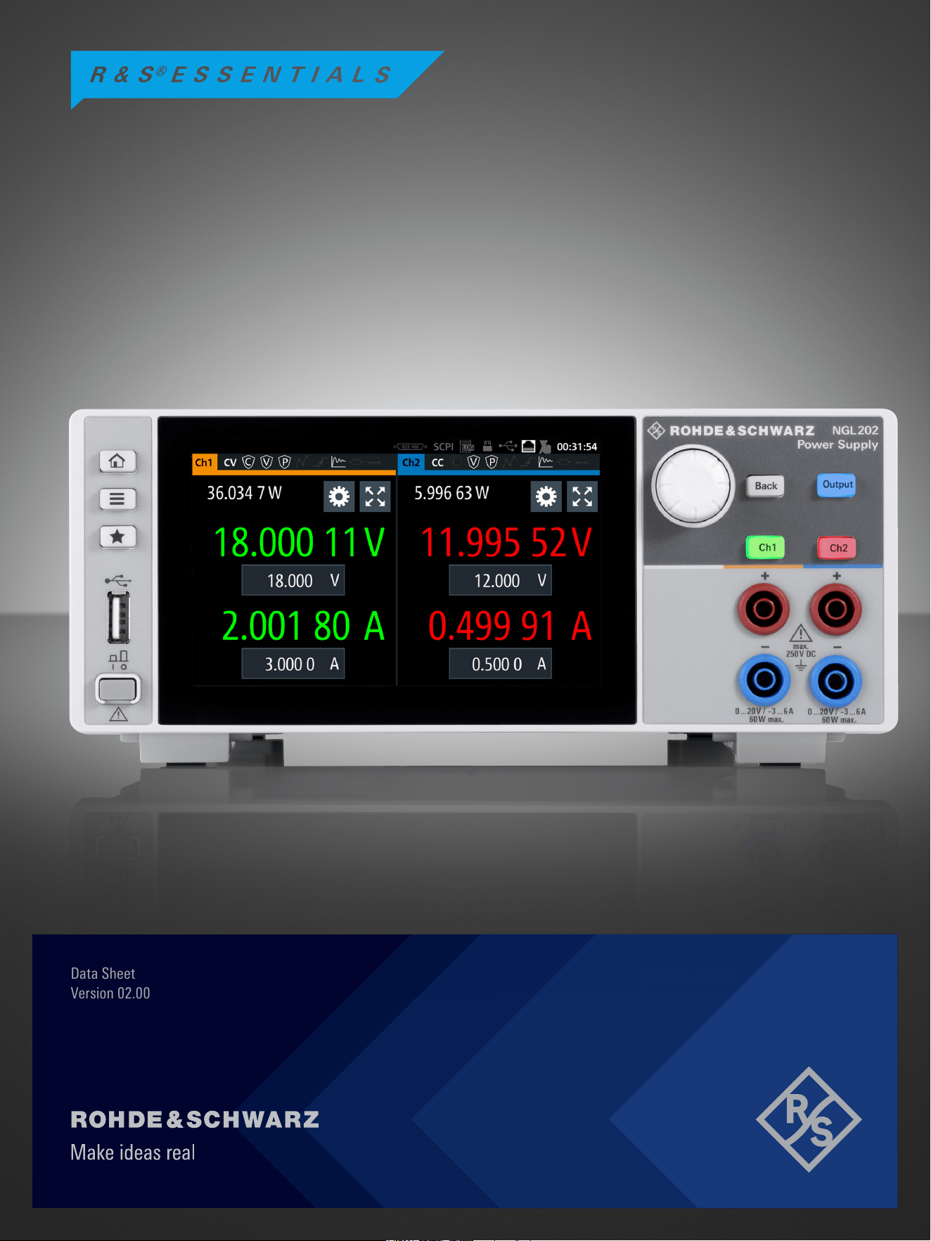
High-resolution touchscreen
The large capacitive touchscreen is the central operating
element for R&S®NGL200 power supplies. Lightly tapping
a numerical value brings up a virtual keyboard to enter the
desired value. Alternatively, the voltage, current and limits
for the various protection functions can be set using the
rotary knob. Functions that are used less frequently can be
accessed and operated via menus.
With its very high resolution of 800×480pixel, the display
sets new standards for power supplies. The large high-res-
olution display makes it easy to read the voltage and cur-
rent fields, even at great distances. A wide variety of addi-
tional information, such as power values or statistics, can
also be displayed. Icons clearly show the status of the set
protection or special functions.
EASY OPERATION
Numerical values can be entered using the virtual touchscreen keyboard or the rotary
knob.
The large high-resolution display makes it easy to read the voltage and current values
(even at great distances) and provides a lot of additional information.
Rohde & Schwarz R&S®NGL200 Power Supply Series 9
Arb sequences can be programmed to run much faster
with the R&S®NGL200 than with other power supplies.
The dwell time for a single voltage or current value can be
set with a resolution of up to 1ms. This makes it possible
to program very short drops in voltage to test the power-
up behavior of a DUT. The dwell times can also be set in
the range of hours to implement test sequences extending
over days or weeks for long-term testing.
EasyRamp function
Sometimes test sequences have to simulate operat-
ing conditions where the abrupt rise of the supply volt-
age has to be avoided. The EasyRamp function of the
R&S®NGL200 power supplies provides the solution. The
output voltage can be increased continuously within a
time frame of 10ms to 10s. The EasyRamp function can
be operated both manually and remotely.
Save and recall instrument settings
The Save and Recall functions make it easy to save and
recall frequently used settings.
Color coding of operating modes
Colors are used to indicate the different modes. For exam-
ple, active channels in constant voltage mode light up
green, while red is used for constant current mode. When
the power supply is in constant resistance mode, the num-
bers are displayed in cyan.
The Output key is used to switch the channels on or off.
When the channels are switched on, the key lights up
blue. Each of the R&S®NGL202 channels can be selected
individually using the channel keys.
QuickArb function
Some applications require the voltage or the current to be
varied during a test sequence, for example when simu-
lating different charging conditions of a battery. The Arb
function allows manual configuration of time/voltage or
time/current sequences via the user interface or program
them via external interfaces.
Other power supplies also offer an Arb function, but the
QuickArb function of the R&S®NGL200 power supplies
sets new standards. More points (4096points) are sup-
ported per cycle. It is also possible to interpolate between
the discrete points and select whether the sequence of
voltage values 1V – 2V – 3V is to be run as steps, or
whether the voltage values are to be increased using linear
interpolation.
All settings and operating modes are easy to read. When the power supply is in constant voltage mode, the numbers and the keys light up green.
Red is used for constant current mode. The Output key lights up blue to indicate that the channels are switched on (active).
10
Digital inputs and outputs are optionally available. They
can be used as trigger, inhibit and fault functions. One
more connection is configurable. The hardware of the
R&S®NGL-K103 option is preinstalled. The function can be
activated using a keycode (to be ordered separately).
Full remote capabilities
For use in test systems, the R&S®NGL200 power supply
series can be remotely controlled. The following interfaces
are available.
USB and LAN
USB and LAN (Ethernet) interfaces are installed as stan-
dard. All supply parameters can be remotely controlled via
these interfaces.
GPIB interface (R&S®NGL-B105 option)
The R&S®NGL-B105 interface with a GPIB (IEEE-488) port
is also available as an option.
Fast on the bus and on the bench
Complicated measurement sequences require ever faster
setting, measuring and command processing times. The
R&S®NGL200 power supplies meet these needs. Thanks
to a state-of-the-art multicore architecture, they not only
process control commands much faster than conventional
power supplies, they process them internally in paral-
lel. Users benefit from this in ATE systems. There are also
advantages in manual operation, such as faster sequences
in Arb mode.
Advanced instrument design: compact form factor, quiet
operation
There is never enough space on the bench or in the rack.
The R&S®NGL200 power supplies take up very little space
thanks to their compact design.
Since the built-in fan is temperature-controlled, it often
runs at a low speed or powers down completely, resulting
in very low operating noise.
IDEAL FOR USE IN LABS AND
TESTSYSTEMS
Tailored for use in labs and system racks
The R&S®NGL200 power supplies are the right choice for
challenging applications. They are used in R&D labs and
integrated into production test systems.
The power supplies can be installed in 19" racks using the
R&S®HZN96 rack adapter. Connectors on the rear panel
and a compact design are important criteria for use in test
systems.
Sense function for lead resistance compensation
There is often a significant voltage drop over the supply
leads, especially in applications with high current con-
sumption. Since power supplies usually maintain a con-
stant output voltage, the voltage on the DUT will be lower
than the voltage displayed on the power supply. The sense
function compensates for this voltage drop over the sup-
ply leads. The voltage actually present at the load is mea-
sured by an additional pair of sense lines, and this value is
used to regulate the voltage directly at the load.
The connectors for the sense lines are located on the rear
panel. The R&S®NGL201 also has sense line connectors on
the front panel.
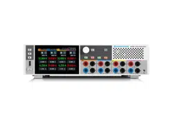
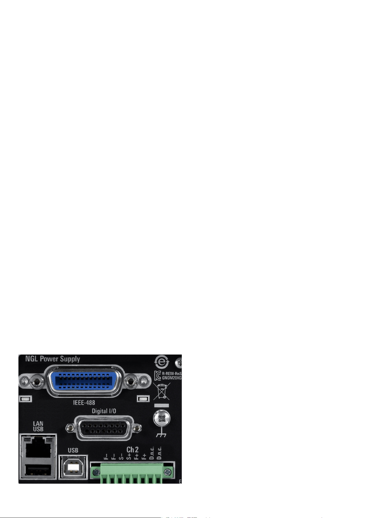
Front and rear connectors
The safety sockets on the front panel of the R&S®NGL200
power supplies are designed for 4 mm banana plugs.
Additional connections for all channels (including sense
lines) are provided on the rear panel to simplify use in rack
systems.
All connections are also provided on the rear panel (example: R&S®NGL202).
X-axis
Y-axis
Specication limit
Actual values with measurement uncertainty and guard band
Specication limit
Measurement uncertainties Guard band
Rohde & Schwarz R&S®NGL200 Power Supply Series 11
SPECIFICATIONS
Definitions
General
Product data applies under the following conditions:
►
Three hours storage at ambient temperature followed by 30minutes warm-up operation
►
All data is valid at +23 °C (–3 °C/+7 °C) after 30 minutes warm-up time.
►
Specified environmental conditions met
►
Recommended calibration interval adhered to
►
All internal automatic adjustments performed, if applicable
Specifications with limits
Represent warranted product performance by means of a range of values for the specified parameter. These specifications are marked with limiting
symbols such as <, ≤, >, ≥, ±, or descriptions such as maximum, limit of, minimum. Compliance is ensured by testing or is derived from the design.
Test limits are narrowed by guard bands to take into account measurement uncertainties, drift and aging, if applicable.
Specifications without limits
Represent warranted product performance for the specified parameter. These specifications are not specially marked and represent values with no or
negligible deviations from the given value (for example, dimensions or resolution of a setting parameter). Compliance is ensured by design.
Typical data (typ.)
Characterizes product performance by means of representative information for the given parameter. When marked with <, > or as a range, it represents
the performance met by approximately 80 % of the instruments at production time. Otherwise, it represents the mean value.
Nominal values (nom.)
Characterize product performance by means of a representative value for the given parameter (for example, nominal impedance). In contrast to typical
data, a statistical evaluation does not take place and the parameter is not tested during production.
Measured values (meas.)
Characterize expected product performance by means of measurement results gained from individual samples.
Uncertainties
Represent limits of measurement uncertainty for a given measurand. Uncertainty is defined with a coverage factor of 2 and has been calculated in line
with the rules of the Guide to the Expression of Uncertainty in Measurement (GUM), taking into account environmental conditions, aging, wear and tear.
Device settings and GUI parameters are indicated as follows: “parameter: value”.
Typical data as well as nominal and measured values are not warranted by Rohde & Schwarz.
In line with the 3GPP/3GPP2 standard, chip rates are specified in million chips per second (Mcps), whereas bit rates and symbol rates are specified in bil-
lion bit per second (Gbps), million bit per second (Mbps), thousand bit per second (kbps), million symbols per second (Msps) or thousand symbols per
second (ksps), and sample rates are specified in million samples per second (Msample/s). Gbps, Mcps, Mbps, Msps, kbps, ksps and Msample/s are not
SI units.

12
All data is valid at +23 °C (–3 °C/+7 °C) after 30 minutes warm-up time.
Specifications
Electrical specifications
Outputs
The channel outputs are galvanically isolated and not connected to ground.
Number of output channels R&S®NGL201 1
R&S®NGL202 2
Maximum total output power R&S®NGL201 60W
R&S®NGL202 120W
Maximum output power per channel 60 W
Output voltage per channel 0 V to 20 V
Maximum output current per channel ≤6V output voltage 6A
>6V output voltage 3 A
Maximum voltage in serial operation R&S®NGL202 40V
Maximum current in parallel operation R&S®NGL202, ≤ 6 V output voltage 12 A
R&S®NGL202, > 6 V output voltage 6 A
Adjustable output impedance –50 mΩ to 100 Ω
Increments 1 mΩ
Recovery time < 10 ms (meas.)
Voltage ripple and noise 20 Hz to 20 MHz
< 500 µV (RMS),
< 2 mV (peak-to-peak) (meas.)
Current ripple and noise 20 Hz to 20 MHz < 1 mA (RMS) (meas.)
Electronic load
yes, R&S®NGL202: both channels
Maximum sink power R&S®NGL201 60 W
R&S®NGL202 120 W (60 W per channel)
1)
Maximum sink current per channel 3 A
Sink modes
constant voltage, constant current, constant
resistance
Constant resistance range 0 Ω to 10 kΩ (0.1 Ω increments)
Load regulation
load change: 10 % to 90 %
Voltage ±(% of output + offset) < 0.01 % + 1 mV
Current ±(% of output + offset) < 0.01 % + 0.1 mA
Load recovery time regulation to within ±20 mV of the set voltage < 30 µs (meas.)
Rise time
10 % to 90 % of rated output voltage,
resistive load
full load: < 125 µs (meas.),
no load: < 125 µs (meas.)
Fall time
90 % to 10 % of rated output voltage,
resistive load
full load: < 125 µs (meas.),
no load: < 125 µs (meas.)
Programming resolution
Voltage 1 mV
Current 0.1 mA
Programming accuracy
Voltage ±(% of the output + offset) < 0.02 % + 3 mV
Current ±(% of the output + offset) < 0.05 % + 2 mA
Output measurements
Measurement functions voltage, current, power, energy
Readback resolution
Voltage 10 μV
Current 10 μA
Readback accuracy
Voltage ±(% of output + offset) < 0.02 % + 2 mV
Current ±(% of output + offset) < 0.05 % + 250μA
Temperature coefficient (per °C)
+23 °C (–3 °C/+7 °C)
Voltage 0.15 × specification/°C
Current 0.15 × specification/°C
Remote sensing
yes, R&S®NGL202: both channels
Maximum sense compensation 2V
Ratings
Maximum voltage to ground 250 V DC
Maximum counter voltage
voltage with the same polarity connected to the
outputs
22V
Maximum reverse voltage
voltage with opposite polarity connected to the
outputs
0.5V
Maximum reverse current for 5 minutes max. 1 A

Rohde & Schwarz R&S®NGL200 Power Supply Series 13
Specifications
Remote control
Command processing time < 6 ms (nom.)
Protection functions
Overvoltage protection adjustable, R&S®NGL202: both channels
Programming resolution 1 mV
Overpower protection adjustable, R&S®NGL202: both channels
Overcurrent protection (electronic fuse) adjustable, R&S®NGL202: both channels
Programming resolution 0.1 mA
Response time (I
load
> I
resp
× 2) at I
load
≥ 2 A < 1.5ms (meas.)
Fuse linking (FuseLink function) R&S®NGL202 yes
Fuse delay at output-on for R&S®NGL202: both channels 0 ms to 10 s (1 ms increments)
Fuse delay time for R&S®NGL202: both channels 0 ms to 10 s (1 ms increments)
Overtemperature protection yes, R&S®NGL202: independent for each channel
Special functions
Output ramp function
EasyRamp
EasyRamp time 10 ms to 10 s (10 ms increments)
Output delay
Synchronicity R&S®NGL202 < 25 µs (meas.)
Delay per channel 1 ms to 10 s (1 ms increments)
Arbitrary function
QuickArb
Parameters voltage, current, time
Maximum number of points 4096
Dwell time 1 ms to 10 h (1 ms increments)
Repetition
continuous or burst mode with 1 to 65 535
repetitions
Trigger
manually via the keyboard, via remote control or
via optional interface
Statistics (sampling time)
voltage minimum, maximum, average (100 ms)
current minimum, maximum, average (100 ms)
power minimum, maximum, average (100 ms)
energy 64 ms
Digital trigger and control interfaces
digital I/O, R&S®NGL-K103
Maximum voltage (IN/OUT) 24 V
Pull-up resistors (IN/OUT) connected to 3.3 V 20 kΩ
Input level low < 0.8 V (nom.)
high > 2.4 V (nom.)
Maximum drain current (OUT) 500 mA
Data logging standard mode
Maximum acquisition rate 10 sample/s
Memory depth internal 800 Mbyte or external memory size
Voltage resolution 10 μV
Voltage accuracy ±(% of output + offset) < 0.02 % + 2 mV
Current resolution 10 μA
Current accuracy ±(% of output + offset) < 0.05 % + 250 μA
Display and interfaces
Display TFT 5" 800 × 480 pixel WVGA Touch
Front panel connections R&S®NGL201
4 mm safety sockets (channel outputs and
remote sensing)
R&S®NGL202 4 mm safety sockets (channel outputs)
Rear panel connections 8-pin connector block per channel
Remote control interfaces standard USB-TMC, USB-CDC (virtual COM port),
LAN
R&S®NGL-K102,
for serial numbers < 110 000 only
WLAN
R&S®NGL-B105 IEEE-488 (GPIB)

14
Specifications
General data
Environmental conditions
Temperature operating temperature range +5 °C to +40 °C
storage temperature range –20 °C to +70 °C
Humidity noncondensing 5 % to 95 %
Altitude operating altitude max. 2000 m above sea level
Power rating
Mains nominal voltage 100 V/115 V/230 V (±10 %)
Mains frequency 50 Hz to 60 Hz
Maximum power consumption 400 W
Mains fuses 2 × T4.0H/250 V
Product conformity
Electromagnetic compatibility
EU: for serial numbers < 110 000, in line with
Radio Equipment Directive 2014/53/EU
applied standards:
►
ETSI EN 300328 V2.1.1
►
E N 6 1 3 2 6 - 1
►
EN 55011 (Class A)
►
EN 55032 (Class A)
►
ETSI EN 301489-1 V2.2.0
►
ETSI EN 301489-17 V3.2.0
EU: for serial numbers ≥ 110 000: in line with
EU EMC Directive 2014/30/EU
applied standards:
►
E N 6 1 3 2 6 - 1
►
EN 55011 (Class A)
Korea KC mark
Electrical safety EU: in line with Low Voltage Directive 2014/35/EU
applied harmonized standard:
EN 61010-1
USA, Canada CSA-C22.2 No. 61010-1
WLAN approvals
Austria, Belgium, Bulgaria, Croatia, Cyprus,
Czech Republic, Denmark, Estonia, Finland,
France, Germany, Greece, Hungary, Iceland,
Ireland, Italy, Latvia, Liechtenstein, Lithuania,
Luxembourg, Malta, Netherlands, Norway,
Poland, Portugal, Romania, Slovakia, Slovenia,
Spain, Sweden, Switzerland, Turkey, United
Kingdom, for serial numbers < 110 000 only
CE0682
Singapore, for serial numbers < 110 000 only iMDA standards DB102020
USA, Canada, for serial numbers < 110 000 only FCC, IC
RoHS in line with EU Directive 2011/65/EU EN IEC 63000
Mechanical resistance
Vibration sinusoidal
5 Hz to 55 Hz, 0.3 mm (peak-to-peak)
55 Hz to 150 Hz, 0.5 g const.,
in line with EN 60068-2-6
wideband noise
8 Hz to 500 Hz, acceleration: 1.2 g (RMS)
in line with EN 60068-2-64
Shock
40 g shock spectrum,
in line with MIL-STD-810E, method 516.4,
procedure I
Mechanical data
Dimensions W × H × D
222 mm × 97 mm × 436 mm
(8.74 in x 3.82 in x 17.17 in)
Weight R&S®NGL201 7.1 kg (15.6 lb)
R&S®NGL202 7.3 kg (16.1 lb)
Rack installation R&S®HZN96 option ½ 19", 2 HU
Recommended calibration interval
operation 40 h/week over entire range of
specified environmental conditions
1 year
1)
Time limited at an operating temperature of >30 °C and total power >90W.
Rohde & Schwarz R&S®NGL200 Power Supply Series 15
ORDERING INFORMATION
Designation Type Order No.
Base unit
Single-channel power supply R&S®NGL201 3638.3376.02
Two-channel power supply R&S®NGL202 3638.3376.03
Accessories supplied
Set of power cables, quick start guide
Interface options
Wireless LAN remote control,
for instruments with serial numbers < 110 000 only
R&S®NGL-K102 3652.6362.02
Digital trigger I/O R&S®NGL-K103 3652.6385.02
IEEE-488 (GPIB) interface R&S®NGL-B105 3652.6356.02
System components
19" rack adapter, 2 HU R&S®HZN96 3638.7813.02
Warranty
Base unit 3 years
All other items
1)
1 year
Service options
Extended warranty, one year R&S®WE1
Please contact your local
Rohde & Schwarz sales office.
Extended warranty, two years R&S®WE2
Extended warranty with calibration coverage, one year R&S®CW1
Extended warranty with calibration coverage, two years R&S®CW2
Extended warranty with a term of one and two years (WE1 and WE2)
Repairs carried out during the contract term are free of charge
2)
Necessary calibration and adjustments carried out during repairs are also covered.
Extended warranty with calibration coverage (CW1 and CW2)
Enhance your extended warranty by adding calibration coverage at a package price. This package ensures that your Rohde & Schwarz product is regularly
calibrated, inspected and maintained during the term of the contract. It includes all repairs
2 )
and calibration at the recommended intervals as well as any
calibration carried out during repairs or option upgrades.
1)
For options installed, the remaining base unit warranty applies if longer than 1 year. Exception: all batteries have a 1 year warranty.
2)
Excluding defects caused by incorrect operation or handling and force majeure. Wear-and-tear parts are not included.
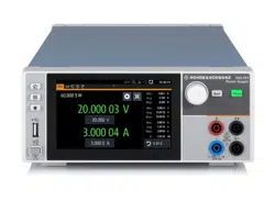
R&S®NGL201, front view
R&S®NGL202, front view R&S®NGL202, rear view
Service that adds value
► Worldwide
► Local and personalized
► Customized and flexible
► Uncompromising quality
► Long-term dependability
R&S® is a registered trademark of Rohde & Schwarz GmbH & Co. KG
Trade names are trademarks of the owners
PD 5216.1057.12 | Version 02.00 | May 2022 (sk)
R&S®NGL200 Power Supply Series
Data without tolerance limits is not binding | Subject to change
© 2018 - 2022 Rohde & Schwarz GmbH & Co. KG | 81671 Munich, Germany
5216.1057.32 02.00 PDP/PDW 1 en
R&S® is a registered trademark of Rohde & Schwarz GmbH & Co. KG
Trade names are trademarks of the owners
PD 5216.1057.32 | Version 02.00 | May 2022 (sk)
R&S®NGL200 Power Supply Series
Data without tolerance limits is not binding | Subject to change
© 2018 - 2022 Rohde & Schwarz GmbH & Co. KG | 81671 Munich, Germany
Sustainable product design
►
Environmental compatibility and eco-footprint
►
Energy efciency and low emissions
►
Longevity and optimized total cost of ownership
Certied Quality Management
ISO 9 001
Rohde & Schwarz customer support
www.rohde-schwarz.com/support
Rohde & Schwarz
The Rohde & Schwarz technology group is among the trail-
blazers when it comes to paving the way for a safer and
connected world with its leading solutions in test & measure-
ment, technology systems and networks & cybersecurity.
Founded more than 85years ago, the group is a reliable
partner for industry and government customers around
the globe. The independent company is headquartered in
Munich, Germany and has an extensive sales and service
network with locations in more than 70countries.
www.rohde-schwarz.com
Rohde & Schwarz training
www.training.rohde-schwarz.com
5216105732