Loading ...
Loading ...
Loading ...
Operating Basics
R&S
®
NGL200/NGM200
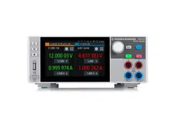
31User Manual 1178.8736.02 ─ 09
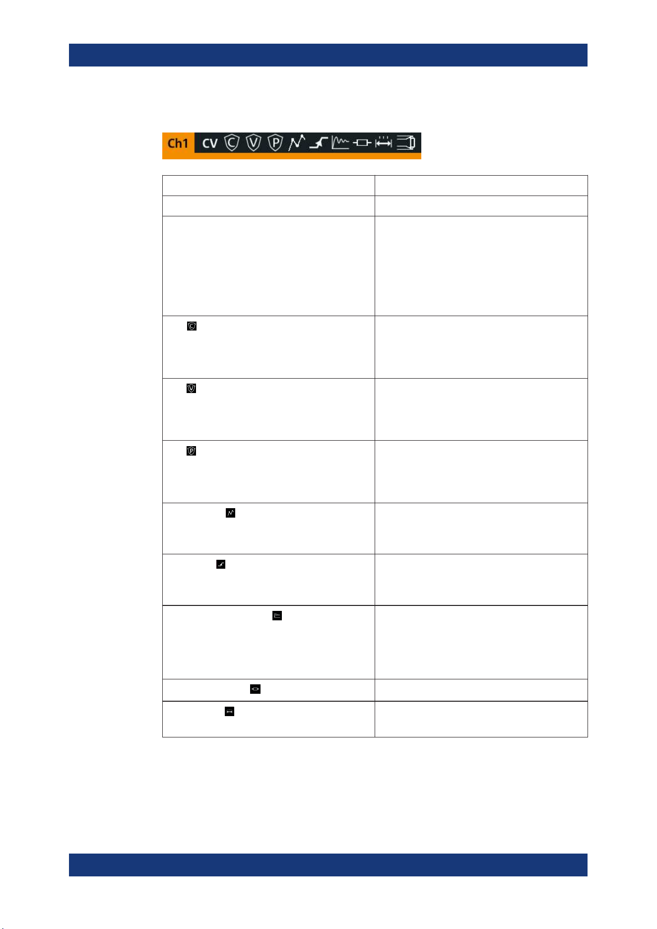
Channel status bar
Function Description
Channel number Channel number indication.
Operation mode The R&S NGL/NGM has three operating modes:
●
CV: Constant voltage mode
●
CC: Constant current mode
●
CR: Constant resistance mode. The
R&S NGL/NGM goes into this mode when
operates in sink mode and the "Constant
Resistance" mode is activated.
See
Chapter 5.5, "Operation Modes", on page 42.
OCP
If enabled, the icon is highlighted in white.
If triggered, the icon blinks.
See Chapter 6.5.1, "Overcurrent Protection (OCP)",
on page 58.
OVP
If enabled, the icon is highlighted in white.
If triggered, the icon blinks.
See Chapter 6.5.2, "Overvoltage Protection (OVP)",
on page 59.
OPP
If enabled, the icon is highlighted in white.
If triggered, the icon blinks.
See Chapter 6.5.3, "Overpower Protection (OPP)",
on page 60.
Arbitrary mode
If enabled, the icon is highlighted in white.
If active, the icon blinks.
See Chapter 6.7.1, "Arbitrary", on page 67.
Ramp mode
If enabled, the icon is highlighted in white.
If active, the icon blinks.
See Chapter 6.7.2, "Ramp", on page 70.
"Fast Transient Response"
If enabled, the icon is highlighted in white.
The time taken for voltage recovery (<=20 mV)
switches between 30 µs and 100 µs.
See
Chapter 6.2.2, "Fast Transient Response",
on page 47.
"Internal Impedance"
If enabled, the icon is highlighted in white.
"Safety Limits"
If enabled, the icon is highlighted in white.
See Chapter 6.5.4, "Safety Limits", on page 61.
Display Overview
Loading ...
Loading ...
Loading ...