Loading ...
Loading ...
Loading ...
Operating Basics
R&S
®
NGL200/NGM200
32User Manual 1178.8736.02 ─ 09
Function Description
"Output Delay"
If enabled, the icon is highlighted in white.
The delay is the time between activation of the out-
put and applying voltage to the output.
See Chapter 6.2.3, "Output", on page 48.
Sense connection
If sense connection is detected, the icon is highligh-
ted in white.
5.1.2 Channel Display Area
The R&S NGL/NGM displays two channels display area (Ch1, Ch2) for NGL202,
NGM202 and a single channel display area (Ch1) for NGL201, NGM201. The respec-
tive channel settings and functions are displayed for each channel.
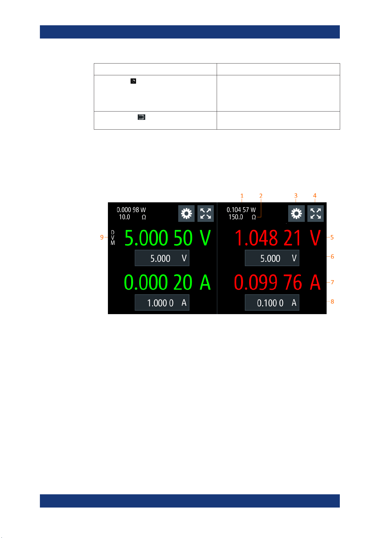
Figure 5-2: Channel display area for 2-channel model
1 = Output power displays in watt
2 = Source output resistance/emulated internal impedance displays in ohms
3 = "Settings" button opens instrument device/channel menu window. Long-press on the button opens the
graphical view window for measurements
4 = "Expand/Collapse" button toggles between home window and channel overview window
5 = Output voltage displays in volt with display resolution of five decimal points
6 = Set voltage level with level limit defined in Safety Limits
7 = Output current displays in ampere with display resolution of five decimal points
8 = Set current level with level limit defined in Safety Limits
9 = DVM function (available only with R&S NGM power supply series)
Operating mode
Different font colors on the screen are used to differentiate the various output status
and operating conditions of the instrument. It is easy to know and confirm the different
output status and operating conditions of the instrument by looking at the colors.
Display Overview
Loading ...
Loading ...
Loading ...