Loading ...
Loading ...
Loading ...
Getting Started
R&S
®
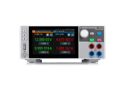
NGL200/NGM200
24User Manual 1178.8736.02 ─ 09
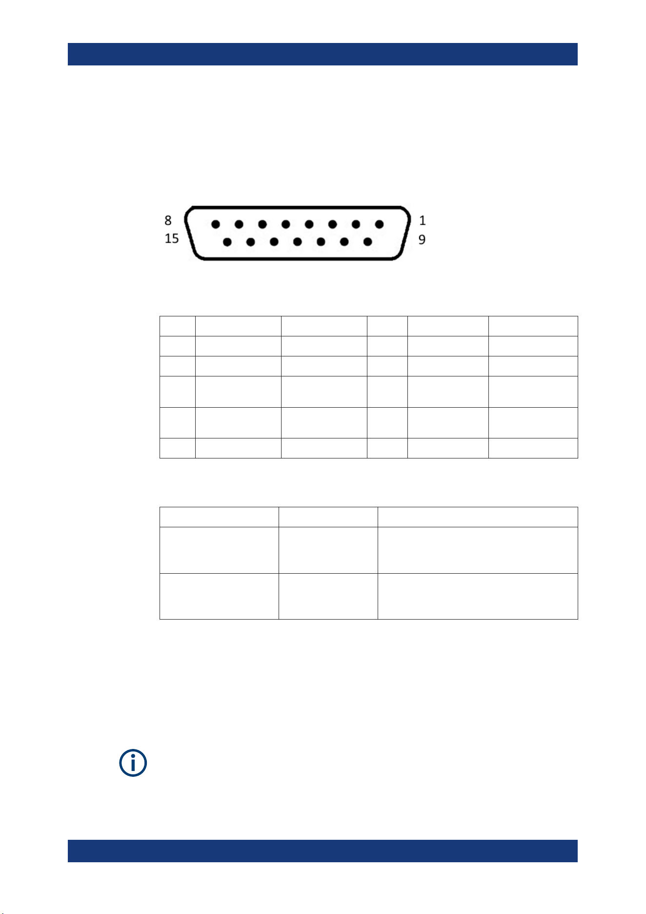
Digital I/O connector (15)
The Digital I/O option (R&S NGL-K103 or R&S NGM-K103) must be installed for this
function to be available in the instrument.
The specified voltages are 0 V to 24 V for all output pins and 0 V to 15 V for all input
pins.
Figure 4-4: Digital I/O connector (female socket front view)
Table 4-2: Digital I/O pin layout
Pin Signal Direction Pin Signal Direction
1 *Inhibit Ch1 IN 9 *Inhibit Ch2 IN
2 Ext. Trigger Ch1 IN 10 Ext. Trigger Ch2 IN
3 Digital In1 IN 11 Digital Output
Fault
OUT
4 Digital Output Out1 OUT 12 Digital Output
Out2
OUT
5 - 8 Gnd - 13 - 15 Gnd -
* The inhibit signals can be used to turn off the outputs by a digital hardware signal.
Table 4-3: Inhibit signals
Signal name Pin Descriptions
Inhibit Ch1 Pin 1 of Digital I/O con-
nector
If the inhibit signal goes active, channel 1 output
is turned off.
The inhibit signal is low active (inverted logic).
Inhibit Ch2 Pin 9 of Digital I/O con-
nector
If the inhibit signal goes active, channel 2 output
is turned off
The inhibit signal is low active (inverted logic).
4.2.2 Switching On the Instrument
Before switching on the instrument, check that all the instructions in the “Basic Safety
Instruction” brochure and safety measures in previous sections are observed. Also,
check if the value on the voltage selector corresponds to the mains voltage (100 V, 115
V or 230 V).
Fuse rating
The R&S NGL/NGM uses the same fuse ratings for all mains voltages.
Instrument Tour
Loading ...
Loading ...
Loading ...