Loading ...
Loading ...
Loading ...
Instrument Functions
R&S
®
NGL200/NGM200
65User Manual 1178.8736.02 ─ 09
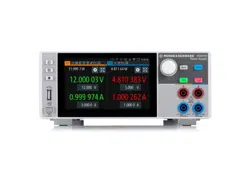
Figure 6-19: Digital output fault signal
Digital I/O connector
The Digital I/O connector is located below the GPIB connector, see
Chapter 4.2.1.2,
"Rear Panel"
, on page 22.
See
Figure 4-4 and Table 4-2 for the Digital I/O connector and pins layout.
1. Press [Settings] key.
The R&S NGL/NGM displays the device/channel menu window.
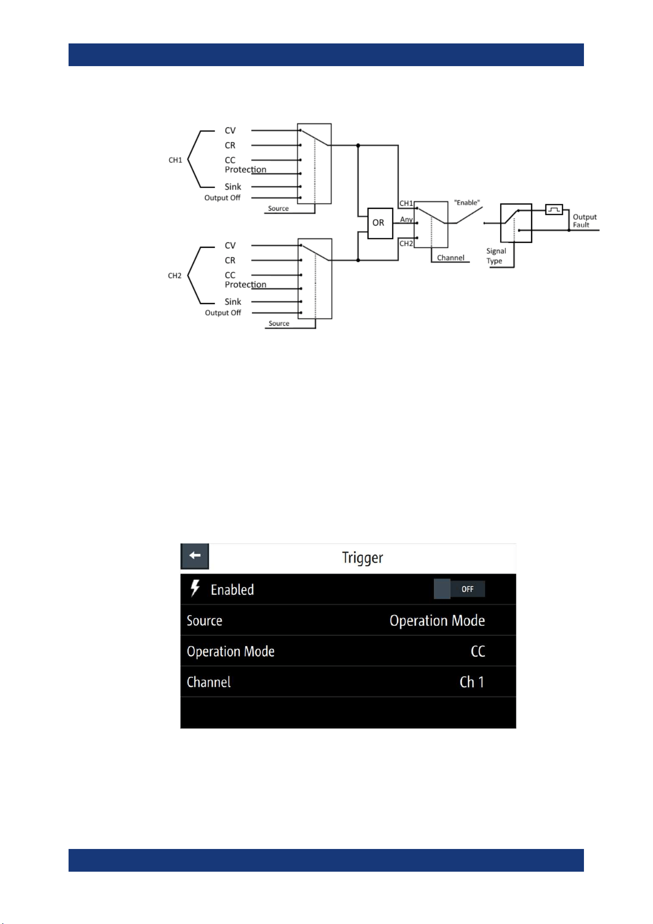
2. Select "Trigger" menu item to set the trigger-in parameter.
The R&S NGL/NGM displays the "Trigger" dialog.
Figure 6-20: An example if Operation Mode is selected as source
3. Select the "Source" to configure the trigger-in parameter.
See
Figure 6-18 for details of the trigger-in parameters.
Trigger / Digital I/O
Loading ...
Loading ...
Loading ...