
Loading ...
Loading ...
Loading ...
Getting Started
R&S
®
NGL200/NGM200
22User Manual 1178.8736.02 ─ 09
Output and channel keys (4)
The channel key allows you to select the power supply channel to source or sink
power. The output key allows you to enable or disable the output power on the channel
key.
Refer to datasheet for the channel voltage/current limits in the source and sink mode.
Output terminals (5)
Depending on the instrument type, one or two output channels are available to source
or sink power.
Both instrument models are equipped with 4 terminals. The NGL201, NGM201 models
provide both the output plus the sense connectors at the front panel while the NGL202,
NGM202 models provide only output terminals for both channels.
USB connector (6)
The USB connector is a Type-A connector. You can connect a USB flash drive to this
connector to perform a firmware update, store logging data or screen shots.
Power key (7)
The [Power] key switches the instrument on and off.
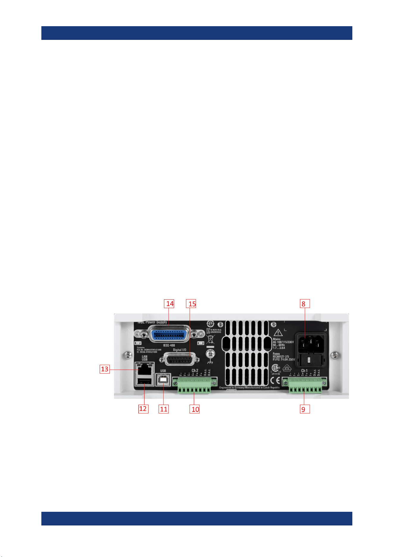
4.2.1.2 Rear Panel
Figure 4-3 shows the rear panel of the R&S NGL/NGM with its connectors.
Figure 4-3: Rear panel of R&S
NGL/NGM with 2 channels
8 = AC inlet with fuse holder and voltage selector
9 = Channel 1 rear panel connector for NGL202, NGM202 models. The two D.n.c. labels for NGM201 are
labeled as DVM+ and DVM-
10 = Channel 2 rear panel connector for NGL202, NGM202 models. The two D.n.c. labels for NGM202 are
labeled as DVM+ and DVM-
11 = USB connector (device)
12 = USB connector (host)
Instrument Tour
Loading ...
Loading ...
Loading ...